wheel alignment INFINITI QX4 2001 Factory User Guide
[x] Cancel search | Manufacturer: INFINITI, Model Year: 2001, Model line: QX4, Model: INFINITI QX4 2001Pages: 2395, PDF Size: 43.2 MB
Page 2226 of 2395

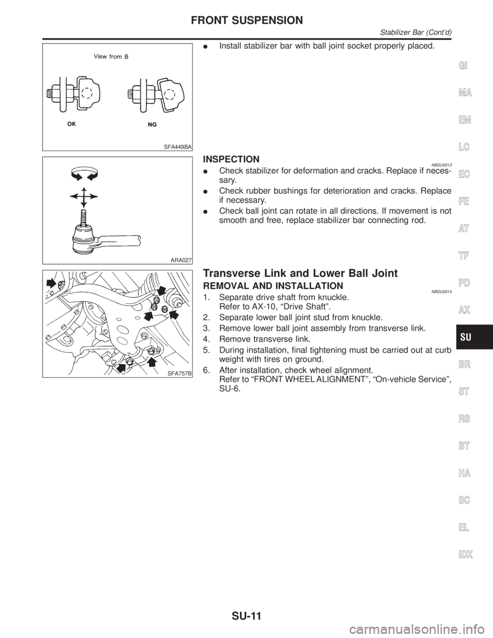
SFA449BA
IInstall stabilizer bar with ball joint socket properly placed.
ARA027
INSPECTIONNBSU0013ICheck stabilizer for deformation and cracks. Replace if neces-
sary.
ICheck rubber bushings for deterioration and cracks. Replace
if necessary.
ICheck ball joint can rotate in all directions. If movement is not
smooth and free, replace stabilizer bar connecting rod.
SFA757B
Transverse Link and Lower Ball Joint
REMOVAL AND INSTALLATIONNBSU00141. Separate drive shaft from knuckle.
Refer to AX-10, ªDrive Shaftº.
2. Separate lower ball joint stud from knuckle.
3. Remove lower ball joint assembly from transverse link.
4. Remove transverse link.
5. During installation, final tightening must be carried out at curb
weight with tires on ground.
6. After installation, check wheel alignment.
Refer to ªFRONT WHEEL ALIGNMENTº, ªOn-vehicle Serviceº,
SU-6.
GI
MA
EM
LC
EC
FE
AT
TF
PD
AX
BR
ST
RS
BT
HA
SC
EL
IDX
FRONT SUSPENSION
Stabilizer Bar (Cont'd)
SU-11
Page 2228 of 2395

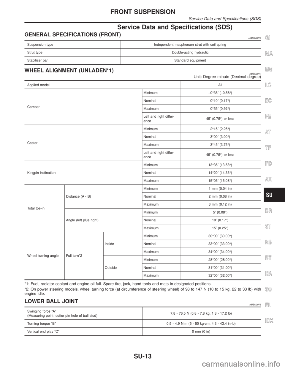
Service Data and Specifications (SDS)
GENERAL SPECIFICATIONS (FRONT)=NBSU0016
Suspension type Independent macpherson strut with coil spring
Strut typeDouble-acting hydraulic
Stabilizer barStandard equipment
WHEEL ALIGNMENT (UNLADEN*1)NBSU0017Unit: Degree minute (Decimal degree)
Applied modelAll
CamberMinimum þ0É35¢(þ0.58É)
Nominal 0É10¢(0.17É)
Maximum 0É55¢(0.92É)
Left and right differ-
ence45¢(0.75É) or less
CasterMinimum 2É15¢(2.25É)
Nominal 3É00¢(3.00É)
Maximum 3É45¢(3.75É)
Left and right differ-
ence45¢(0.75É) or less
Kingpin inclinationMinimum 13É35¢(13.58É)
Nominal 14É20¢(14.33É)
Maximum 15É05¢(15.08É)
Total toe-inDistance (A - B)Minimum 1 mm (0.04 in)
Nominal 2 mm (0.08 in)
Maximum 3 mm (0.12 in)
Angle (left plus right)Minimum 5¢(0.08É)
Nominal 10¢(0.17É)
Maximum 15¢(0.25É)
Wheel turning angle Full turn*2InsideMinimum 30É00¢(30.00É)
Nominal 33É00¢(33.00É)
Maximum 34É00¢(34.00É)
OutsideMinimum 28É00¢(28.00É)
Nominal 31É00¢(31.00É)
Maximum 32É00¢(32.00É)
*1: Fuel, radiator coolant and engine oil full. Spare tire, jack, hand tools and mats in designated positions.
*2: On power steering models, wheel turning force (at circumference of steering wheel) of 98 to 147 N (10 to 15 kg, 22 to 33 lb) with
engine idle.
LOWER BALL JOINTNBSU0018
Swinging force ªAº
(Measuring point: cotter pin hole of ball stud)7.8 - 76.5 N (0.8 - 7.8 kg, 1.8 - 17.2 lb)
Turning torque ªBº 0.5 - 4.9 N´m (5 - 50 kg-cm, 4.3 - 43.4 in-lb)
Vertical end play ªCº0mm(0in)
GI
MA
EM
LC
EC
FE
AT
TF
PD
AX
BR
ST
RS
BT
HA
SC
EL
IDX
FRONT SUSPENSION
Service Data and Specifications (SDS)
SU-13
Page 2230 of 2395

SBR686C
Precautions
PRECAUTIONSNBSU0021IWhen installing rubber parts, final tightening must be car-
ried out under unladen condition* with tires on ground.
*Fuel, radiator coolant and engine oil full. Spare tire, jack,
hand tools and mats in designated positions.
IUse flare nut wrench when removing and installing brake
tubes.
IAfter installing removed suspension parts, check wheel
alignment and adjust if necessary.
IAlways torque brake lines when installing.
Preparation
COMMERCIAL SERVICE TOOLSNBSU0023
Tool name Description
1 Flare nut crowfoot
2 Torque wrench
NT360
Removing and installing each brake piping
a: 10 mm (0.39 in)
Noise, Vibration and Harshness (NVH)
Troubleshooting
NBSU0036Refer to ªNoise, Vibration and Harshness (NVH) Troubleshootingº,
ªFRONT SUSPENSIONº, SU-3.
GI
MA
EM
LC
EC
FE
AT
TF
PD
AX
BR
ST
RS
BT
HA
SC
EL
IDX
REAR SUSPENSION
Precautions
SU-15