ESP INFINITI QX4 2001 Factory Service Manual
[x] Cancel search | Manufacturer: INFINITI, Model Year: 2001, Model line: QX4, Model: INFINITI QX4 2001Pages: 2395, PDF Size: 43.2 MB
Page 2 of 2395

FOREWORD
This manual contains maintenance and repair procedures for the
2001 INFINITI QX4.
In order to assure your safety and the efficient functioning of the
vehicle, this manual should be read thoroughly. It is especially
important that the PRECAUTIONS in the GI section be completely
understood before starting any repair task.
All information in this manual is based on the latest product infor-
mation at the time of publication. The right is reserved to make
changes in specifications and methods at any time without notice.
IMPORTANT SAFETY NOTICE
The proper performance of service is essential for both the safety of
the technician and the efficient functioning of the vehicle.
The service methods in this Service Manual are described in such a
manner that the service may be performed safely and accurately.
Service varies with the procedures used, the skills of the technician
and the tools and parts available. Accordingly, anyone using service
procedures, tools or parts which are not specifically recommended
by INFINITI must first be completely satisfied that neither personal
safety nor the vehicle's safety will be jeopardized by the service
method selected.
Page 14 of 2395
IThe threads in one or more of the converter bolt holes are damaged.
ITransmission failure did not display evidence of damaged or worn internal parts, steel particles or clutch
plate lining material in unit and inside the fluid filter.
IVehicle has been exposed to high mileage (only). The exception may be where the torque converter clutch
dampener plate lining has seen excess wear by vehicles operated in heavy and/or constant traffic, such
as taxi, delivery or police use.
ATF COOLER SERVICENBAT0004S02Replace ATF cooler if excessive foreign material is found in oil pan or clogging strainer.
Replace radiator lower tank (which includes ATF cooler) with a new one and flush cooler line using cleaning
solvent and compressed air. Refer to LC-19, ªREMOVAL AND INSTALLATIONº.
OBD-II SELF-DIAGNOSISNBAT0004S03IA/T self-diagnosis is performed by the TCM in combination with the ECM. The results can be read through
the blinking pattern of the O/D OFF indicator or the malfunction indicator lamp (MIL). Refer to the table on
AT-38 for the indicator used to display each self-diagnostic result.
IThe self-diagnostic results indicated by the MIL are automatically stored in both the ECM and TCM
memories.
Always perform the procedure ªHOW TO ERASE DTCº on AT-35 to complete the repair and avoid
unnecessary blinking of the MIL.
IThe following self-diagnostic items can be detected using ECM self-diagnostic results mode* only when
the O/D OFF indicator lamp does not indicate any malfunctions.
þ PNP switch
þ A/T 1st, 2nd, 3rd, or 4th gear function
þ A/T TCC S/V function (lock-up)
*: For details of OBD-II, refer to EC-59, ªIntroductionº.
ICertain systems and components, especially those related to OBD, may use the new style slide-
locking type harness connector. For description and how to disconnect, refer to EL-5, ªDescrip-
tionº.
Wiring Diagrams and Trouble DiagnosisNBAT0005When you read wiring diagrams, refer to the following:
IGI-11, ªHOW TO READ WIRING DIAGRAMSº.
IEL-9, ªPOWER SUPPLY ROUTINGº for power distribution circuit.
When you perform trouble diagnosis, refer to the following:
IGI-35, ªHOW TO FOLLOW TEST GROUP IN TROUBLE DIAGNOSISº.
IGI-24, ªHOW TO PERFORM EFFICIENT DIAGNOSIS FOR AN ELECTRICAL INCIDENTº.
GI
MA
EM
LC
EC
FE
TF
PD
AX
SU
BR
ST
RS
BT
HA
SC
EL
IDX
PRECAUTIONS
Service Notice or Precautions (Cont'd)
AT-9
Page 31 of 2395

TCM FUNCTION=NBAT0013S03The function of the TCM is to:
IReceive input signals sent from various switches and sensors.
IDetermine required line pressure, shifting point, lock-up operation, and engine brake operation.
ISend required output signals to the respective solenoids.
INPUT/OUTPUT SIGNAL OF TCMNBAT0013S04
Sensors and solenoid valves Function
InputPNP switch Detects select lever position and sends a signal to TCM.
Throttle position sensor Detects throttle valve position and sends a signal to TCM.
Closed throttle position switch Detects throttle valve's fully-closed position and sends a signal to TCM.
Wide open throttle position switchDetects a throttle valve position of greater than 1/2 of full throttle and sends
a signal to TCM.
Engine speed signal From ECM.
A/T fluid temperature sensor Detects transmission fluid temperature and sends a signal to TCM.
Revolution sensor Detects output shaft rpm and sends a signal to TCM.
Vehicle speed sensorUsed as an auxiliary vehicle speed sensor. Sends a signal when revolution
sensor (installed on transmission) malfunctions.
Overdrive control switchSends a signal, which prohibits a shift to ªD
4º (overdrive) position, to the
TCM.
ASCD control unitSends the cruise signal and ªD
4º (overdrive) cancellation signal from ASCD
control unit to TCM.
Turbine revolution sensor Sends an input shaft revolution signal.
Stop lamp switch Sends the lock-up release signal to the TCM at time of D
4(lock-up).
OutputShift solenoid valve A/BSelects shifting point suited to driving conditions in relation to a signal sent
from TCM.
Line pressure solenoid valveRegulates (or decreases) line pressure suited to driving conditions in rela-
tion to a signal sent from TCM.
Torque converter clutch solenoid
valveRegulates (or decreases) lock-up pressure suited to driving conditions in
relation to a signal sent from TCM.
Overrun clutch solenoid valveControls an ªengine brakeº effect suited to driving conditions in relation to a
signal sent from TCM.
O/D OFF indicator lamp Shows TCM faults, when A/T control components malfunction.
Control MechanismNBAT0180LINE PRESSURE CONTROLNBAT0180S01TCM has the various line pressure control characteristics to meet
the driving conditions.
An ON-OFF duty signal is sent to the line pressure solenoid valve
based on TCM characteristics.
Hydraulic pressure on the clutch and brake is electronically con-
trolled through the line pressure solenoid valve to accommodate
engine torque. This results in smooth shift operation.
OVERALL SYSTEM
Control System (Cont'd)
AT-26
Page 32 of 2395
SAT003J
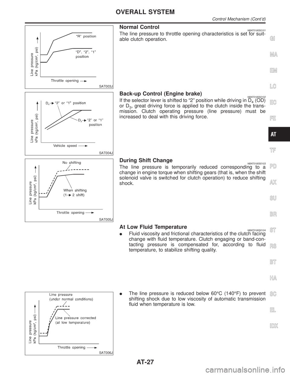
Normal ControlNBAT0180S0101The line pressure to throttle opening characteristics is set for suit-
able clutch operation.
SAT004J
Back-up Control (Engine brake)NBAT0180S0102If the selector lever is shifted to ª2º position while driving in D4(OD)
or D
3, great driving force is applied to the clutch inside the trans-
mission. Clutch operating pressure (line pressure) must be
increased to deal with this driving force.
SAT005J
During Shift ChangeNBAT0180S0103The line pressure is temporarily reduced corresponding to a
change in engine torque when shifting gears (that is, when the shift
solenoid valve is switched for clutch operation) to reduce shifting
shock.
At Low Fluid TemperatureNBAT0180S0104IFluid viscosity and frictional characteristics of the clutch facing
change with fluid temperature. Clutch engaging or band-con-
tacting pressure is compensated for, according to fluid
temperature, to stabilize shifting quality.
SAT006J
IThe line pressure is reduced below 60ÉC (140ÉF) to prevent
shifting shock due to low viscosity of automatic transmission
fluid when temperature is low.
GI
MA
EM
LC
EC
FE
TF
PD
AX
SU
BR
ST
RS
BT
HA
SC
EL
IDX
OVERALL SYSTEM
Control Mechanism (Cont'd)
AT-27
Page 33 of 2395
SAT007J
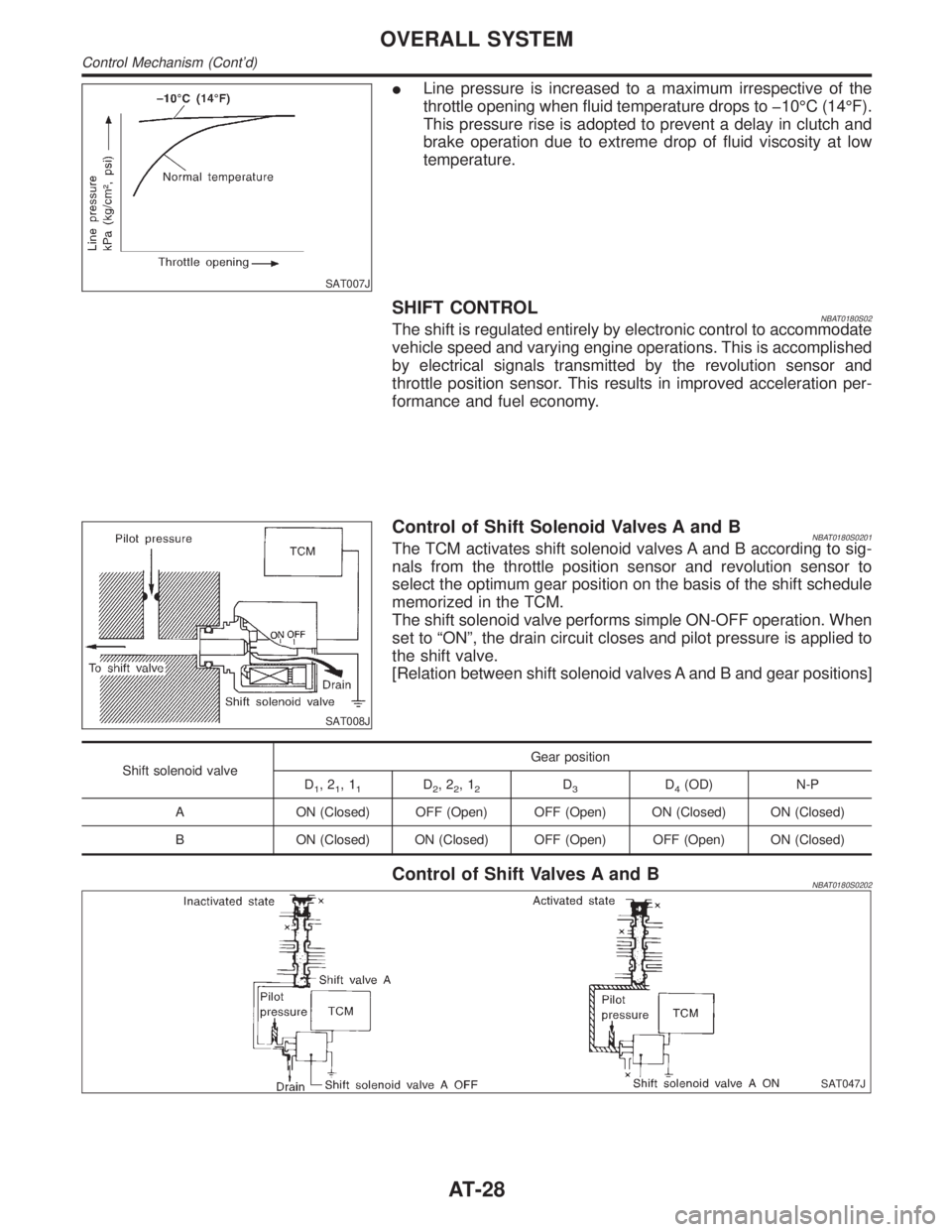
ILine pressure is increased to a maximum irrespective of the
throttle opening when fluid temperature drops to þ10ÉC (14ÉF).
This pressure rise is adopted to prevent a delay in clutch and
brake operation due to extreme drop of fluid viscosity at low
temperature.
SHIFT CONTROLNBAT0180S02The shift is regulated entirely by electronic control to accommodate
vehicle speed and varying engine operations. This is accomplished
by electrical signals transmitted by the revolution sensor and
throttle position sensor. This results in improved acceleration per-
formance and fuel economy.
SAT008J
Control of Shift Solenoid Valves A and BNBAT0180S0201The TCM activates shift solenoid valves A and B according to sig-
nals from the throttle position sensor and revolution sensor to
select the optimum gear position on the basis of the shift schedule
memorized in the TCM.
The shift solenoid valve performs simple ON-OFF operation. When
set to ªONº, the drain circuit closes and pilot pressure is applied to
the shift valve.
[Relation between shift solenoid valves A and B and gear positions]
Shift solenoid valveGear position
D
1,21,11D2,22,12D3D4(OD) N-P
A ON (Closed) OFF (Open) OFF (Open) ON (Closed) ON (Closed)
B ON (Closed) ON (Closed) OFF (Open) OFF (Open) ON (Closed)
Control of Shift Valves A and BNBAT0180S0202
SAT047J
OVERALL SYSTEM
Control Mechanism (Cont'd)
AT-28
Page 36 of 2395
SAT015J
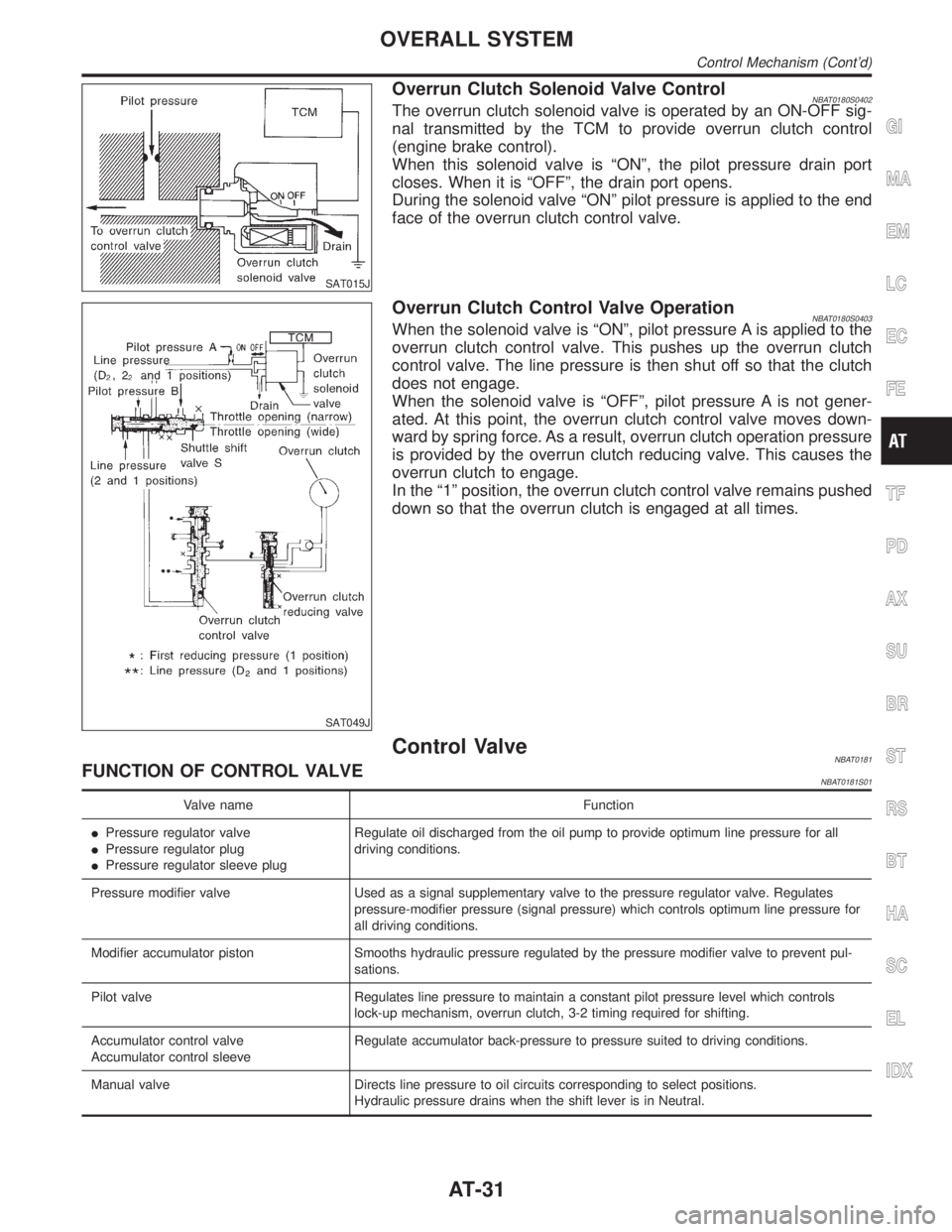
Overrun Clutch Solenoid Valve ControlNBAT0180S0402The overrun clutch solenoid valve is operated by an ON-OFF sig-
nal transmitted by the TCM to provide overrun clutch control
(engine brake control).
When this solenoid valve is ªONº, the pilot pressure drain port
closes. When it is ªOFFº, the drain port opens.
During the solenoid valve ªONº pilot pressure is applied to the end
face of the overrun clutch control valve.
SAT049J
Overrun Clutch Control Valve OperationNBAT0180S0403When the solenoid valve is ªONº, pilot pressure A is applied to the
overrun clutch control valve. This pushes up the overrun clutch
control valve. The line pressure is then shut off so that the clutch
does not engage.
When the solenoid valve is ªOFFº, pilot pressure A is not gener-
ated. At this point, the overrun clutch control valve moves down-
ward by spring force. As a result, overrun clutch operation pressure
is provided by the overrun clutch reducing valve. This causes the
overrun clutch to engage.
In the ª1º position, the overrun clutch control valve remains pushed
down so that the overrun clutch is engaged at all times.
Control ValveNBAT0181FUNCTION OF CONTROL VALVENBAT0181S01
Valve name Function
IPressure regulator valve
IPressure regulator plug
IPressure regulator sleeve plugRegulate oil discharged from the oil pump to provide optimum line pressure for all
driving conditions.
Pressure modifier valve Used as a signal supplementary valve to the pressure regulator valve. Regulates
pressure-modifier pressure (signal pressure) which controls optimum line pressure for
all driving conditions.
Modifier accumulator piston Smooths hydraulic pressure regulated by the pressure modifier valve to prevent pul-
sations.
Pilot valve Regulates line pressure to maintain a constant pilot pressure level which controls
lock-up mechanism, overrun clutch, 3-2 timing required for shifting.
Accumulator control valve
Accumulator control sleeveRegulate accumulator back-pressure to pressure suited to driving conditions.
Manual valve Directs line pressure to oil circuits corresponding to select positions.
Hydraulic pressure drains when the shift lever is in Neutral.
GI
MA
EM
LC
EC
FE
TF
PD
AX
SU
BR
ST
RS
BT
HA
SC
EL
IDX
OVERALL SYSTEM
Control Mechanism (Cont'd)
AT-31
Page 38 of 2395
IntroductionNBAT0014The A/T system has two self-diagnostic systems.
The first is the emission-related on board diagnostic system (OBD-II) performed by the TCM in combination
with the ECM. The malfunction is indicated by the MIL (malfunction indicator lamp) and is stored as a DTC in
the ECM memory but not the TCM memory.
The second is the TCM original self-diagnosis indicated by the O/D OFF indicator lamp. The malfunction is
stored in the TCM memory. The detected items are overlapped with OBD-II self-diagnostic items. For detail,
refer to AT-38.
OBD-II Function for A/T SystemNBAT0182The ECM provides emission-related on board diagnostic (OBD-II) functions for the A/T system. One function
is to receive a signal from the TCM used with OBD-related parts of the A/T system. The signal is sent to the
ECM when a malfunction occurs in the corresponding OBD-related part. The other function is to indicate a
diagnostic result by means of the MIL (malfunction indicator lamp) on the instrument panel. Sensors, switches
and solenoid valves are used as sensing elements.
The MIL automatically illuminates in One or Two Trip Detection Logic when a malfunction is sensed in rela-
tion to A/T system parts.
One or Two Trip Detection Logic of OBD-IINBAT0015ONE TRIP DETECTION LOGICNBAT0015S01If a malfunction is sensed during the first test drive, the MIL will illuminate and the malfunction will be stored
in the ECM memory as a DTC. The TCM is not provided with such a memory function.
TWO TRIP DETECTION LOGICNBAT0015S02When a malfunction is sensed during the first test drive, it is stored in the ECM memory as a 1st trip DTC
(diagnostic trouble code) or 1st trip freeze frame data. At this point, the MIL will not illuminate. Ð First Trip
If the same malfunction as that experienced during the first test drive is sensed during the second test drive,
the MIL will illuminate. Ð Second Trip
A/T-related parts for which the MIL illuminates during the first or second test drive are listed below.
ItemsMIL
One trip detection Two trip detection
Shift solenoid valve A Ð DTC: P0750 X
Shift solenoid valve B Ð DTC: P0755 X
Throttle position sensor or switch Ð DTC: P1705 X
Except aboveX
The ªtripº in the ªOne or Two Trip Detection Logicº means a driving mode in which self-diagnosis is performed
during vehicle operation.
OBD-II Diagnostic Trouble Code (DTC)NBAT0016HOW TO READ DTC AND 1ST TRIP DTCNBAT0016S01DTC and 1st trip DTC can be read by the following methods.
(
with CONSULT-II orGST)CONSULT-II or GST (Generic Scan Tool) Examples: P0705, P0710, P0720,
P0725, etc.
These DTCs are prescribed by SAE J2012.
(CONSULT-II also displays the malfunctioning component or system.)
I1st trip DTC No. is the same as DTC No.
IOutput of the diagnostic trouble code indicates that the indicated circuit has a malfunction.
However, in case of the Mode II and GST they do not indicate whether the malfunction is still
occurring or occurred in the past and returned to normal.
CONSULT-II can identify them as shown below. Therefore, using CONSULT-II (if available) is rec-
ommended.
A sample of CONSULT-II display for DTC and 1st trip DTC is shown on the next page. DTC or 1st trip DTC
of a malfunction is displayed in SELF-DIAGNOSTIC RESULTS mode for ªENGINEº with CONSULT-II. Time
data indicates how many times the vehicle was driven after the last detection of a DTC.
GI
MA
EM
LC
EC
FE
TF
PD
AX
SU
BR
ST
RS
BT
HA
SC
EL
IDX
ON BOARD DIAGNOSTIC SYSTEM DESCRIPTION
Introduction
AT-33
Page 58 of 2395

SAT631IB
IntroductionNBAT0019
SAT632I
SEF234G
The TCM receives a signal from the vehicle speed sensor, throttle
position sensor or PNP switch and provides shift control or lock-up
control via A/T solenoid valves.
The TCM also communicates with the ECM by means of a signal
sent from sensing elements used with the OBD-related parts of the
A/T system for malfunction-diagnostic purposes. The TCM is
capable of diagnosing malfunctioning parts while the ECM can
store malfunctions in its memory.
Input and output signals must always be correct and stable in the
operation of the A/T system. The A/T system must be in good
operating condition and be free of valve seizure, solenoid valve
malfunction, etc.
It is much more difficult to diagnose a problem that occurs intermit-
tently rather than continuously. Most intermittent problems are
caused by poor electric connections or improper wiring. In this
case, careful checking of suspected circuits may help prevent the
replacement of good parts.
A visual check only may not find the cause of the problems. A road
test with CONSULT-II (or GST) or a circuit tester connected should
be performed. Follow the ªWork Flowº. Refer to AT-57.
Before undertaking actual checks, take a few minutes to talk with
a customer who approaches with a driveability complaint. The cus-
tomer can supply good information about such problems, espe-
cially intermittent ones. Find out what symptoms are present and
under what conditions they occur. A ªDiagnostic Worksheetº like the
example (AT-55) should be used.
Start your diagnosis by looking for ªconventionalº problems first.
This will help troubleshoot driveability problems on an electronically
controlled engine vehicle.
Also check related Service bulletins.GI
MA
EM
LC
EC
FE
TF
PD
AX
SU
BR
ST
RS
BT
HA
SC
EL
IDX
TROUBLE DIAGNOSIS Ð INTRODUCTION
Introduction
AT-53
Page 67 of 2395

SAT209GA
Line Pressure TestNBAT0023ILocation of line pressure test ports.
IAlways replace line pressure plugs as they are self-seal-
ing bolts.
SAT647B
LINE PRESSURE TEST PROCEDURENBAT0023S011. Check A/T fluid and engine oil levels. If necessary, add fluid
and oil.
2. Drive vehicle for approx. 10 minutes or until fluid and oil reach
operating temperature.
ATF operating temperature:
50 - 80ÉC (122 - 176ÉF)
SAT518GB
SAT519GB
3. Install pressure gauge to corresponding line pressure port.
SAT513G
4. Set parking brake and block wheels.
IContinue to depress brake pedal fully while line pressure
test is being performed at stall speed.
TROUBLE DIAGNOSIS Ð BASIC INSPECTION
Line Pressure Test
AT-62
Page 99 of 2395

Terminal
No.Wire color Item ConditionJudgement
standard
(Approx.)
24 W/GASCD OD cut
signal
When ªACCELº set switch on ASCD cruise is
released.5 - 10V
When ªACCELº set switch on ASCD cruise is
applied.Less than 2V
25 B Ground
Ð0V
26 GPNP switch ª1º
position
When setting selector lever to ª1º position.Battery volt-
age
When setting selector lever to other positions. 0V
27 G/WPNP switch ª2º
positionWhen setting selector lever to ª2º position.Battery volt-
age
When setting selector lever to other positions. 0V
28 R/YPower source
(Memory back-up)
or
When turning ignition switch to ªOFFº.Battery volt-
age
When turning ignition switch to ªONº.Battery volt-
age
29 WRevolution sensor
(Measure in AC
range)
When vehicle cruises at 30 km/h (19 MPH).1V or more
Voltage rises
gradually in
response to
vehicle speed.
When vehicle parks. 0V
30*2 W (RX)
ÐÐ
31*2 L (TX) Ð Ð
32 P/BThrottle position
sensor
(Power source)Ignition switch ªONº. 4.5 - 5.5V
Ignition switch ªOFFº. 0V
33*1 G/R LAN Ð Ð
34 LPNP switch ªDº
position
When setting selector lever to ªDº position.Battery volt-
age
When setting selector lever to other positions. 0V
35 YPNP switch ªRº
positionWhen setting selector lever to ªRº position.Battery volt-
age
When setting selector lever to other positions. 0V
36 PPNP switch ªNº or
ªPº positionWhen setting selector lever to ªNº or ªPº posi-
tion.Battery volt-
age
When setting selector lever to other positions. 0V
37 Ð Ð Ð Ð
38 WTurbine revolution
sensor (Measure
in AC range)
When engine is running at 1,000 rpm1.2V
Voltage rises
gradually in
response to
engine speed.
TROUBLE DIAGNOSIS Ð GENERAL DESCRIPTION
TCM Terminals and Reference Value (Cont'd)
AT-94