ECO mode INFINITI QX4 2001 Factory Service Manual
[x] Cancel search | Manufacturer: INFINITI, Model Year: 2001, Model line: QX4, Model: INFINITI QX4 2001Pages: 2395, PDF Size: 43.2 MB
Page 1888 of 2395

SYSTEM DESCRIPTION=NBHA0056Component PartsNBHA0056S01Intake door control system components are:
1) Auto amp.
2) Intake door motor
3) A/C LAN system (PBR built-in mode motor and air mix door motor)
4) In-vehicle sensor
5) Ambient sensor
6) Sunload sensor
7) Intake sensor
System OperationNBHA0056S02The intake door control determines intake door position based on the ambient temperature, the intake air
temperature and the in-vehicle temperature. When the ECON, DEFROST, or OFF switches are pushed, the
auto amplifier sets the intake door at the ªFreshº position.
RHA874H
Intake Door Control SpecificationNBHA0056S03
RHA136G
GI
MA
EM
LC
EC
FE
AT
TF
PD
AX
SU
BR
ST
RS
BT
SC
EL
IDX
TROUBLE DIAGNOSES
Intake Door Motor (Cont'd)
HA-89
Page 1896 of 2395

SYSTEM DESCRIPTION=NBHA0062Component partsNBHA0062S01Fan speed control system components are:
1) Auto amp.
2) Fan control amp.
3) A/C LAN system (PBR built-in mode door motor and air mix door motor)
4) In-vehicle sensor
5) Ambient sensor
6) Sunload sensor
7) Intake sensor
System OperationNBHA0062S02
SHA006FF
Automatic ModeNBHA0062S03In the automatic mode, the blower motor speed is calculated by the automatic amplifier based on inputs from
the PBR, in-vehicle sensor, sunload sensor, intake sensor and ambient sensor. The blower motor applied
voltage ranges from approximately 5 volts (lowest speed) to 12 volts (highest speed).
The control blower speed (in the range of 5 to 12V), the automatic amplifier supplies a gate voltage to the fan
control amplifier. Based on this voltage, the fan control amplifier controls the voltage supplied to the blower
motor.
Starting Fan Speed ControlNBHA0062S04Start Up From ªCOLD SOAKº Condition (Automatic mode)NBHA0062S0401In a cold start up condition where the engine coolant temperature is below 50ÉC (122ÉF), the blower will not
operate for a short period of time (up to 126 seconds). The exact start delay time varies depending on the
ambient and engine coolant temperature.
In the most extreme case (very low ambient) the blower starting delay will be 126 seconds as described above.
After this delay, the blower will operate at low speed until the engine coolant temperature rises above 55ÉC
(131ÉF), at which time the blower speed will increase to the objective speed.
Start Up From Normal or ªHOT SOAKº Condition (Automatic mode)
NBHA0062S0402The blower will begin operation momentarily after the AUTO button is pushed. The blower speed will gradu-
ally rise to the objective speed over a time period of 3 seconds or less (actual time depends on the objective
blower speed).
GI
MA
EM
LC
EC
FE
AT
TF
PD
AX
SU
BR
ST
RS
BT
SC
EL
IDX
TROUBLE DIAGNOSES
Blower Motor (Cont'd)
HA-97
Page 1927 of 2395

ECON (ECONOMY) Mode
TROUBLE DIAGNOSIS PROCEDURE FOR ECON (ECONOMY) MODE=NBHA0103SYMPTOM:
IECON mode does not operate.
Inspection FlowNBHA0103S01Without Navigation SystemNBHA0103S0101
SHA920EA
*1: HA-72 *2: HA-66 *3: HA-45
TROUBLE DIAGNOSES
ECON (ECONOMY) Mode
HA-128
Page 1928 of 2395

With Navigation SystemNBHA0103S0102
RHA887H
*1: HA-72 *2: HA-66 *3: HA-45
RHA050G
Ambient Sensor Circuit
COMPONENT DESCRIPTIONNBHA0039The ambient sensor is attached in front of the driver's side con-
denser. It detects ambient temperature and converts it into a resis-
tance value which is then input into the auto amplifier.
AMBIENT TEMPERATURE INPUT PROCESSNBHA0040The automatic amplifier includes a ªprocessing circuitº for the ambi-
ent sensor input. However, when the temperature detected by the
ambient sensor increases quickly, the processing circuit retards the
auto amp. function. It only allows the auto amp. to recognize an
ambient temperature increase of 0.33ÉC (0.6ÉF) per 100 seconds.
As an example, consider stopping for a cup of coffee after high
speed driving. Although the actual ambient temperature has not
changed, the temperature detected by the ambient sensor will
increase. This is because the heat from the engine compartment
can radiate to the front grille area, location of the ambient sensor.
GI
MA
EM
LC
EC
FE
AT
TF
PD
AX
SU
BR
ST
RS
BT
SC
EL
IDX
TROUBLE DIAGNOSES
ECON (ECONOMY) Mode (Cont'd)
HA-129
Page 1957 of 2395

5. If a leak detector detects a leak, verify at least once by blow-
ing compressed air into area of suspected leak, then repeat
check as outlined above.
6. Do not stop when one leak is found. Continue to check for
additional leaks at all system components.
If no leaks are found, perform steps7-10.
7. Start engine.
8. Set the heater A/C control as follows:
1) A/C switch ON.
2) Face mode
3) Recirculation switch ON
4) Max cold temperature
5) Fan speed high
9. Run engine at 1,500 rpm for at least 2 minutes.
10. Turn engine off and perform leak check again following steps
4 through 6 above.
SHA839E
Refrigerant leaks should be checked immediately after
stopping the engine. Begin with the leak detector at the
compressor. The pressure on the high pressure side will
gradually drop after refrigerant circulation stops and pres-
sure on the low pressure side will gradually rise, as shown
in the graph. Some leaks are more easily detected when
pressure is high.
11. Before connecting ACR4 to vehicle, check ACR4 gauges. No
refrigerant pressure should be displayed. If pressure is
displayed, recover refrigerant from equipment lines and then
check refrigerant purity.
12. Confirm refrigerant purity in supply tank using ACR4 and refrig-
erant identifier.
13. Confirm refrigerant purity in vehicle A/C system using ACR4
and refrigerant identifier.
14. Discharge A/C system using approved refrigerant recovery
equipment. Repair the leaking fitting or component as neces-
sary.
15. Evacuate and recharge A/C system and perform the leak test
to confirm no refrigerant leaks.
16. Conduct A/C performance test to ensure system works
properly.
SERVICE PROCEDURE
Refrigerant Lines (Cont'd)
HA-158
Page 1967 of 2395

S/VCSW - Wiring diagram ...........................EC-493
Swirl control valve control solenoid
valve .........................................................EC-458
Swirl control valve control vacuum
check switch .............................................EC-493
SWL/V - Wiring diagram ..............................EC-458
Symbols and abbreviations .............................GI-10
Symptom matrix chart...................................EC-118
System readiness test (SRT) code ................EC-61
T
2-4WD shift solenoid valve............................TF-111
Tachometer .....................................................EL-94
Tail lamp ..........................................................EL-61
TAIL/L - Wiring diagram ..................................EL-63
TCM circuit diagram ........................................AT-13
TCM inspection table ......................................AT-92
TFTS - Wiring diagram .................................EC-311
THEFT - Wiring diagram ...............................EL-300
Theft warning system....................................EL-294
Thermometer .................................................EL-110
Thermostat ......................................................LC-16
Three way catalyst function (Left bank) .......EC-347
Three way catalyst function (Right
bank) .........................................................EC-347
Three way catalyst precautions.........................GI-6
Throttle bodies ...............................................EM-12
Throttle position sensor (TPS) .....................EC-174
Throttle position sensor adjustment .............EC-101
Throttle position switch ...........EC-431, AT-184, 264
Tie-rod .............................................................ST-21
Tie-rod ball joints.............................................ST-21
Tightening torque of standard bolts.................GI-50
Timing chain ...................................................EM-20
Tire rotation ....................................................MA-24
Tire size ...........................................................GI-44
TLID - Wiring diagram ..................................EL-179
Tooth contact (front final drive 4WD) .............PD-29
Tooth contact diff. ...........................................PD-56
Torque converter installation .........................AT-278
Torque convertor clutch solenoid
valve ..................................................AT-152, 161
Tow truck towing ..............................................GI-47
Towing point.....................................................GI-49
TP/SW - Wiring diagram ..............................EC-434
TPS - Wiring diagram...................................EC-180
Transfer control unit inspection table..............TF-55
Transfer dropping resistor .............................TF-112
Transfer fluid replacement (Part time
4WD model) ...............................................MA-22
Transfer fluid temperature sensor .................TF-111
Transfer motor ...............................................TF-117
Transfer motor relay ......................................TF-113
Transfer serial number ....................................GI-43
TRANSMT - Wiring diagram .........................EL-325
Tread-FR&RR (Dimensions)............................GI-43
Trim .................................................................BT-28
Trouble diagnoses ...........................................GI-34
Trunk lid opener, electric...............................EL-178Turbine revolution sensor..............................AT-202
TURN - Wiring diagram ..................................EL-77
Turn signal lamp .............................................EL-75
Two trip detection logic ..................................EC-59
Two-pole lift .....................................................GI-47
U
Under body .....................................................BT-60
V
Vacuum cut valve ...........................................EC-32
Vacuum cut valve bypass valve.....EC-32, 585, 591
Vacuum hose (brake system).........................BR-21
Vacuum hose drawing (Engine control) .........EC-26
Valve clearance ..............................................EM-52
Valve guide.....................................................EM-43
Valve seat.......................................................EM-45
Valve spring....................................................EM-46
Vehicle identification number...........................GI-42
Vehicle recovery (freeing a stuck
vehicle) .........................................................GI-49
Vehicle speed sensor (VSS) ........................EC-417
VENT/V - Wiring diagram ............EC-376, 555, 576
Ventilation air filter ........................................HA-159
VIAS .............................................................EC-610
VIAS - Wiring diagram .................................EC-610
Viscosity number (SAE) .................................MA-12
VSS - Wiring diagram ..................................EC-420
W
Wait detection switch ....................................TF-112
WARN - Wiring diagram................................EL-115
Warning chime ..............................................EL-125
Warning lamps ..............................................EL-114
Washer, front .................................................EL-136
Washer, rear..................................................EL-141
Water pump ....................................................LC-12
Water temperature gauge ...............................EL-94
Weatherstrip - See Exterior ............................BT-35
Wheel balance ...............................................MA-24
Wheel bearing (front)........................................AX-4
Wheel bearing (rear) ......................................AX-18
Wheel hub (front)..............................................AX-6
Wheel sensors (ABS)...............................BR-56, 80
Wheel size .......................................................GI-44
Wheelarch height .............................................SU-5
Wheelbase (Dimensions) ................................GI-43
Wide open & closed throttle position
switch ........................................................EC-174
Width (Dimensions) .........................................GI-43
WINDOW - Wiring diagram ..........................EL-245
Window, door ..................................................BT-18
Window, rear side ...........................................BT-55
Window, side - See Rear side window ...........BT-55
ALPHABETICAL INDEX
IDX-8
Page 1996 of 2395

MAINTENANCE
SECTION
MA
CONTENTS
PRECAUTIONS...............................................................2
Supplemental Restraint System (SRS)²AIR
BAG²and²SEAT BELT PRE-TENSIONER²...............2
PREPARATION...............................................................3
Special Service Tool ....................................................3
Commercial Service Tool .............................................3
GENERAL MAINTENANCE............................................4
PERIODIC MAINTENANCE............................................6
Schedule 1 ...................................................................7
EMISSION CONTROL SYSTEM MAINTENANCE.........7
CHASSIS AND BODY MAINTENANCE........................8
Schedule 2 ...................................................................9
EMISSION CONTROL SYSTEM MAINTENANCE.........9
CHASSIS AND BODY MAINTENANCE......................10
RECOMMENDED FLUIDS AND LUBRICANTS........... 11
Fluids and Lubricants ................................................ 11
SAE Viscosity Number ..............................................12
GASOLINE ENGINE OIL..........................................12
GEAR OIL...............................................................12
Anti-freeze Coolant Mixture Ratio .............................12
ENGINE MAINTENANCE..............................................13
Checking Drive Belts .................................................13
Changing Engine Coolant..........................................14
-DRAINING ENGINE COOLANT-..............................14
-REFILLING ENGINE COOLANT-..............................15
-FLUSHING COOLING SYSTEM-..............................16
Checking Fuel Lines ..................................................16
Changing Fuel Filter ..................................................16
WITH CONSULT-II..............................................16
WITHOUT CONSULT-II.......................................17
Changing Air Cleaner Filter .......................................17
VISCOUS PAPER TYPE...........................................17
Changing Engine Oil..................................................18
Changing Oil Filter .....................................................18
Changing Spark Plugs ...............................................19
Checking EVAP Vapor Lines .....................................20
CHASSIS AND BODY MAINTENANCE.......................21
Checking Exhaust System.........................................21
Checking A/T Fluid ....................................................21
Changing A/T Fluid ....................................................21Checking All-mode 4WD Transfer Fluid ....................22
Changing All-mode 4WD Transfer Fluid ....................22
Checking Propeller Shaft ...........................................23
Greasing Propeller Shaft ...........................................23
Checking Differential Gear Oil ...................................23
Changing Differential Gear Oil ..................................24
LIMITED-SLIP DIFFERENTIAL GEAR........................24
Balancing Wheels ......................................................24
Tire Rotation ..............................................................24
Checking Brake Fluid Level and Leaks.....................25
Checking Brake Lines and Cables ............................25
Checking Disc Brake .................................................25
ROTOR...................................................................25
CALIPER.................................................................25
PAD........................................................................25
Checking Drum Brake ...............................................26
WHEEL CYLINDER..................................................26
DRUM.....................................................................26
LINING....................................................................26
TEMPORARY METHOD FOR CHECKING LINING
WEAR
.....................................................................26
Checking Steering Gear, Linkage and Transfer
Gear ...........................................................................26
STEERING GEAR....................................................26
STEERING LINKAGE...............................................26
STEERING TRANSFER GEAR..................................26
Checking Power Steering Fluid and Lines ................27
CHECKING FLUID LEVEL........................................27
CHECKING LINES...................................................27
Lubricating Locks, Hinges and Hood Latches...........27
Checking Seat Belts, Buckles, Retractors,
Anchors and Adjusters...............................................28
SERVICE DATA AND SPECIFICATIONS (SDS).........29
Engine Maintenance ..................................................29
DRIVE BELT DEFLECTION......................................29
DRIVE BELT TENSION............................................29
SPARK PLUG TYPE................................................29
Chassis and Body Maintenance ................................29
WHEEL BALANCE...................................................29
GI
EM
LC
EC
FE
AT
TF
PD
AX
SU
BR
ST
RS
BT
HA
SC
EL
IDX
Page 2006 of 2395

NBMA0005
Fluids and LubricantsNBMA0005S01
Capacity (Approximate)
Recommended Fluids/Lubricants
US measure Imp measure Liter
Engine oilDrain and
refillWith oil filter 5-1/4 qt 4-3/8 qt 5.0
IAPI Certification Mark*1
IAPI grade SG/SH, Energy Conserv-
ingI&IIorAPIgrade SJ, Energy
Conserving*1
IILSAC grade GF-I & GF-II*1 Without oil
filter5-1/8 qt 4-1/4 qt 4.8
Dry engine
(Engine overhaul)7-1/4 qt 6 qt 6.8
Cooling system (With reservoir) 9-3/4 qt 8-1/8 qt 9.2Genuine Nissan anti-freeze coolant or
equivalent
All-mode 4WD transfer fluid 3-1/8 qt 2-5/8 qt 3.0Nissan Matic ªDº (Continental U.S. and
Alaska) or Canada NISSAN Automatic
Transmission Fluid*2
Differential
carrier gear
oilFront (4WD) 3-7/8 pt 3-1/4 pt 1.85Standard differential gear: API GL-5*1
Limited-slip differential (LSD) gear:
Use only LSD gear oil API GL-5 and
SAE 80W-90*5 approved for Nissan
LSD*6. Rear 5-7/8 pt 4-7/8 pt 2.8
Automatic transmission fluid2WD
9 qt 7-1/2 qt 8.5Nissan Matic ªDº (Continental U.S. and
Alaska) or Canada NISSAN Automatic
Transmission Fluid*3 4WD
Power steering fluid Ð Ð Ð Genuine NISSAN PSF II or equivalent*7
Brake fluid Ð Ð ÐGenuine Nissan Brake Fluid*4 or
equivalent DOT 3 (U.S. FMVSS No.
116)
Propeller shaft grease Ð Ð ÐNLGI No. 2 (Molybdenum disulphide
lithium soap base)
Multi-purpose grease Ð Ð Ð NLGI No. 2 (Lithium soap base)
*1: For further details, see ªSAE Viscosity Numberº.
*2: Outside the continental United States and Alaska contact an authorized INFINITI dealership for more information regarding suitable
fluids, including recommended brand(s) of DEXRON
TMIII/MERCONTMAutomatic Transmission Fluid.
*3: DEXRONTMIII/MERCONTMor equivalent may also be used. Outside the continental United States and Alaska contact an autho-
rized INFINITI dealership for more information regarding suitable fluids, including recommended brand(s) of DEXRONTMIII/MERCONTM
Automatic Transmission Fluid.
*4: Available in mainland U.S.A. through your INFINITI dealer.
*5: SAE 90 is acceptable in ambient temperatures above þ18ÉC (0ÉF).
*6: Contact an INFINITI dealer for a list of approved oils.
*7: Genuine NISSAN PSF, Canada NISSAN Automatic Transmission Fluid, DEXRON
TMIII/MERCONTMor equivalent ATF may also be
used.
GI
EM
LC
EC
FE
AT
TF
PD
AX
SU
BR
ST
RS
BT
HA
SC
EL
IDX
RECOMMENDED FLUIDS AND LUBRICANTS
Fluids and Lubricants
MA-11
Page 2017 of 2395

2WD, 4WD model
8.5(9 US qt, 7-1/2 Imp qt)
Drain plug:
: 29 - 39 N´m (3.0 - 4.0 kg-m, 22 - 29 ft-lb)
4. Run engine at idle speed for five minutes.
5. Check fluid level and condition. Refer to MA-21, ªChecking A/T
Fluidº. If fluid is still dirty, repeat steps 2 through 5.
SMA439B
Checking All-mode 4WD Transfer FluidNBMA0022Check for oil leakage and fluid level.
A/T fluid is used for the all-mode 4WD transfer in the factory.
Never start engine while checking fluid level.
Filler plug:
: 10 - 20 N´m (1.0 - 2.0 kg-m, 87 - 174 in-lb)
SMA444B
Changing All-mode 4WD Transfer FluidNBMA0023When changing all-mode 4WD transfer fluid completely, A/T fluid
may be used.
Fluid grade:
Nissan Matic ªDº (Continental U.S. and Alaska) or
Canada NISSAN Automatic Transmission Fluid.
Refer to ªFluids and Lubricantsº, ªRECOMMENDED
FLUIDS AND LUBRICANTSº, MA-11.
Fluid capacity:
3.0(3-1/8 US qt, 2-5/8 Imp qt)
Drain plug:
: 10 - 20 N´m (1.0 - 2.0 kg-m, 87 - 174 in-lb)
CHASSIS AND BODY MAINTENANCE
Changing A/T Fluid (Cont'd)
MA-22
Page 2118 of 2395

Trouble Diagnoses Introduction=NBRS0040CAUTION:
IDo not use electrical test equipment on any circuit related to the SRS unless instructed to in this
Service Manual. Spiral cable and wiring harnesses covered with yellow insulation tape either just
before the harness connectors or for the complete harness are related to the SRS.
IDo not attempt to repair, splice or modify the SRS wiring harness. If the harness is damaged,
replace it with a new one.
IKeep ground portion clean.
DIAGNOSIS FUNCTIONNBRS0040S01The SRS self-diagnosis results can be read by using ªAIR BAGº warning lamp and/or CONSULT-II. The read-
ing of these results is accomplished using one of two modes Ð ªUser modeº and ªDiagnosis modeº.
The User mode is exclusively prepared for the customer (driver). This mode warns the driver of a system
malfunction through the operation of the ªAIR BAGº warning lamp.
The Diagnosis mode allows the technician to locate and inspect the malfunctioning part.
The mode applications for the ªAIR BAGº warning lamp and CONSULT-II are as follows:
User mode Diagnosis mode Display type
ªAIR BAGº warning lamp X X ON-OFF operation
CONSULT-II Ð X Monitoring
NOTE:
Seat belt pre-tensioner malfunction is indicated by ªAIR BAGº warning lamp.
DIAGNOSIS MODE FOR CONSULT-IINBRS0040S02IªSELF-DIAG [CURRENT]º
A current Self-diagnosis result (also indicated by the number of warning lamp flashes in the Diagnosis
mode) is displayed on the CONSULT-II screen in real time. This refers to a malfunctioning part requiring
repairs.
IªSELF-DIAG [PAST]º
Diagnosis results previously stored in the memory are displayed on the CONSULT-II screen. The stored
results are not erased until memory erasing is executed.
IªTROUBLE DIAG RECORDº
With TROUBLE DIAG RECORD, diagnosis results previously erased by a reset operation can be displayed
on the CONSULT-II screen.
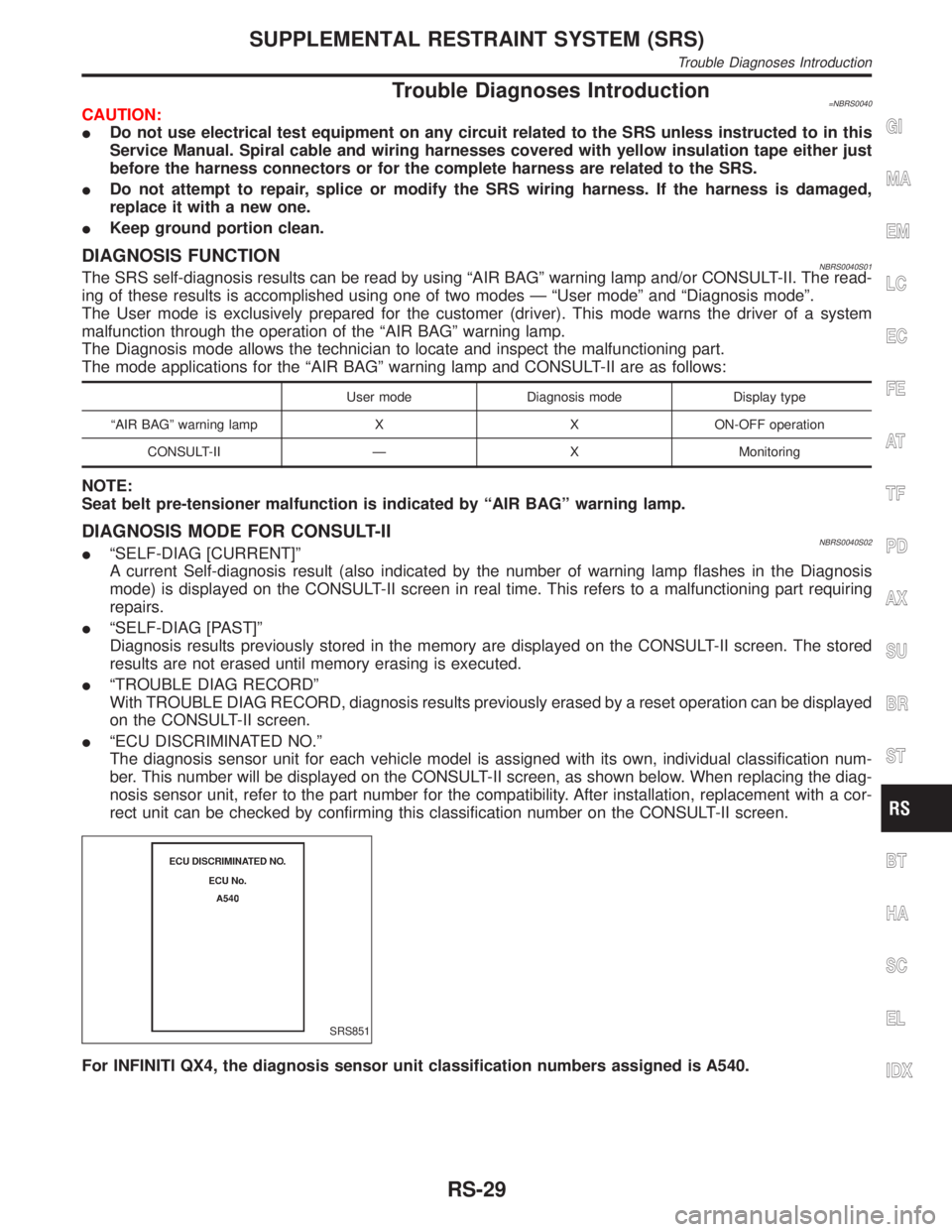
IªECU DISCRIMINATED NO.º
The diagnosis sensor unit for each vehicle model is assigned with its own, individual classification num-
ber. This number will be displayed on the CONSULT-II screen, as shown below. When replacing the diag-
nosis sensor unit, refer to the part number for the compatibility. After installation, replacement with a cor-
rect unit can be checked by confirming this classification number on the CONSULT-II screen.
SRS851
For INFINITI QX4, the diagnosis sensor unit classification numbers assigned is A540.
GI
MA
EM
LC
EC
FE
AT
TF
PD
AX
SU
BR
ST
BT
HA
SC
EL
IDX
SUPPLEMENTAL RESTRAINT SYSTEM (SRS)
Trouble Diagnoses Introduction
RS-29