oil INFINITI QX4 2001 Factory Service Manual
[x] Cancel search | Manufacturer: INFINITI, Model Year: 2001, Model line: QX4, Model: INFINITI QX4 2001Pages: 2395, PDF Size: 43.2 MB
Page 2026 of 2395

PROPELLER SHAFT &
DIFFERENTIAL CARRIER
SECTION
PD
CONTENTS
PROPELLER SHAFT......................................................3
Noise, Vibration and Harshness (NVH)
Troubleshooting ...........................................................3
NVH TROUBLESHOOTING CHART............................3
Components.................................................................4
FRONT PROPELLER SHAFT.....................................4
REAR PROPELLER SHAFT.......................................5
On-vehicle Service.......................................................6
PROPELLER SHAFT VIBRATION...............................6
APPEARANCE CHECKING........................................6
Removal and Installation .............................................6
Inspection.....................................................................7
Disassembly.................................................................7
CENTER BEARING - 2WD -.......................................7
JOURNAL (71H AND 80B)..........................................8
Assembly .....................................................................9
CENTER BEARING - 2WD -.......................................9
JOURNAL (71H AND 80B)..........................................9
Service Data and Specifications (SDS)..................... 11
GENERAL SPECIFICATIONS................................... 11
SERVICE DATA....................................................... 11
SNAP RING (80B).................................................... 11
SNAP RING (71H)...................................................12
R200A
FRONT FINAL DRIVE...................................................13
Preparation ................................................................13
SPECIAL SERVICE TOOLS......................................13
Noise, Vibration and Harshness (NVH)
Troubleshooting .........................................................15
On-vehicle Service.....................................................15
FRONT OIL SEAL REPLACEMENT...........................15
REAR COVER GASKET REPLACEMENT..................16
Components...............................................................17
Removal and Installation ...........................................18
REMOVAL...............................................................18
INSTALLATION........................................................18
Disassembly...............................................................18
PRE-INSPECTION...................................................18
FINAL DRIVE HOUSING..........................................19
DIFFERENTIAL CASE..............................................21
DIFFERENTIAL SIDE SHAFT...................................22
Inspection...................................................................23
RING GEAR AND DRIVE PINION.............................23
DIFFERENTIAL CASE ASSEMBLY...........................23
BEARING................................................................23
Adjustment .................................................................24
SIDE BEARING PRELOAD.......................................24
PINION GEAR HEIGHT AND PINION BEARING
PRELOAD
...............................................................25
TOOTH CONTACT...................................................29
Assembly ...................................................................30
DIFFERENTIAL SIDE SHAFT...................................30
DIFFERENTIAL CASE..............................................31
FINAL DRIVE HOUSING..........................................32
Service Data and Specifications (SDS).....................36
R200A.....................................................................36
H233B
REAR FINAL DRIVE.....................................................38
Preparation ................................................................38
SPECIAL SERVICE TOOLS......................................38
Noise, Vibration and Harshness (NVH)
Troubleshooting .........................................................40
On-vehicle Service.....................................................40
FRONT OIL SEAL REPLACEMENT...........................40
Components...............................................................42
Removal and Installation ...........................................43
REMOVAL...............................................................43
INSTALLATION........................................................43
Disassembly...............................................................43
PRE-INSPECTION...................................................43
DIFFERENTIAL CARRIER........................................44
DIFFERENTIAL CASE..............................................46
Inspection...................................................................47
RING GEAR AND DRIVE PINION.............................47
DIFFERENTIAL CASE ASSEMBLY...........................47
BEARING................................................................47
Limited Slip Differential ..............................................47
PREPARATION FOR DISASSEMBLY........................47
GI
MA
EM
LC
EC
FE
AT
TF
AX
SU
BR
ST
RS
BT
HA
SC
EL
IDX
Page 2028 of 2395

Noise, Vibration and Harshness (NVH)
Troubleshooting
=NBPD0049NVH TROUBLESHOOTING CHARTNBPD0049S01Use the chart below to help you find the cause of the symptom. If necessary, repair or replace these parts.
Reference pageÐ
Ð
Ð
Ð
PD-6
PD-6
PD-23, 47
PD-29, 56
PD-23, 47
PD-18, 43
Ð
Ð
Ð
Ð
AX-3
AX-3
SU-3
SU-3
SU-3
BR-6
ST-6
Possible cause and
SUSPECTED PARTS
Uneven rotation torque
Excessive center bearing axial end play
Center bearing mounting (insulator) cracks, damage or deterioration
Excessive joint angle
Rotation imbalance
Excessive runout
Rough gear tooth
Improper gear contact
Tooth surfaces worn
Incorrect backlash
Companion flange excessive runout
Improper gear oil
PROPELLER SHAFT
DIFFERENTIAL
DRIVE SHAFT
AXLE
SUSPENSION
TIRES
ROAD WHEEL
BRAKES
STEERING
SymptomPROPEL-
LER
SHAFTNoise´´´´´´ ´´´´´´´´
Shake´ ´´´´´´´
Vibration´´´´´´ ´´´´ ´
DIFFER-
ENTIALNoise´´´´´´´ ´´´´´´´
´: Applicable
GI
MA
EM
LC
EC
FE
AT
TF
AX
SU
BR
ST
RS
BT
HA
SC
EL
IDX
PROPELLER SHAFT
Noise, Vibration and Harshness (NVH) Troubleshooting
PD-3
Page 2039 of 2395

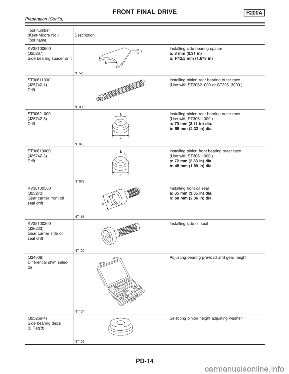
Tool number
(Kent-Moore No.)
Tool nameDescription
KV38100600
(J25267)
Side bearing spacer drift
NT528
Installing side bearing spacer
a: 8 mm (0.31 in)
b: R42.5 mm (1.673 in)
ST30611000
(J25742-1)
Drift
NT090
Installing pinion rear bearing outer race
(Use with ST30621000 or ST30613000.)
ST30621000
(J25742-5)
Drift
NT073
Installing pinion rear bearing outer race
(Use with ST30611000.)
a: 79 mm (3.11 in) dia.
b: 59 mm (2.32 in) dia.
ST30613000
(J25742-3)
Drift
NT073
Installing pinion front bearing outer race
(Use with ST30611000.)
a: 72 mm (2.83 in) dia.
b: 48 mm (1.89 in) dia.
KV38100500
(J25273)
Gear carrier front oil
seal drift
NT115
Installing front oil seal
a: 85 mm (3.35 in) dia.
b: 60 mm (2.36 in) dia.
KV38100200
(J26233)
Gear carrier side oil
seal drift
NT120
Installing side oil seal
(J34309)
Differential shim selec-
tor
NT134
Adjusting bearing pre-load and gear height
(J25269-4)
Side bearing discs
(2 Req'd)
NT136
Selecting pinion height adjusting washer
FRONT FINAL DRIVER200A
Preparation (Cont'd)
PD-14
Page 2040 of 2395

Tool number
(Kent-Moore No.)
Tool nameDescription
(J8129)
Spring gauge
NT127
Measuring carrier turning torque
Noise, Vibration and Harshness (NVH)
Troubleshooting
NBPD0050Refer to ªNVH TROUBLESHOOTING CHARTº, PD-3.
SPD476A
On-vehicle Service
FRONT OIL SEAL REPLACEMENTNBPD00141. Remove front propeller shaft.
2. Loosen drive pinion nut.
Tool number: KV38108300 (J44195)
SPD734
3. Remove companion flange.
SPD735
4. Remove front oil seal.
GI
MA
EM
LC
EC
FE
AT
TF
AX
SU
BR
ST
RS
BT
HA
SC
EL
IDX
FRONT FINAL DRIVER200A
Preparation (Cont'd)
PD-15
Page 2041 of 2395

SPD736
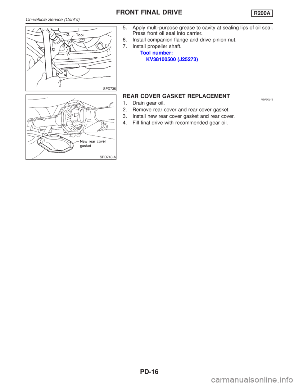
5. Apply multi-purpose grease to cavity at sealing lips of oil seal.
Press front oil seal into carrier.
6. Install companion flange and drive pinion nut.
7. Install propeller shaft.
Tool number:
KV38100500 (J25273)
SPD740-A
REAR COVER GASKET REPLACEMENTNBPD00151. Drain gear oil.
2. Remove rear cover and rear cover gasket.
3. Install new rear cover gasket and rear cover.
4. Fill final drive with recommended gear oil.
FRONT FINAL DRIVER200A
On-vehicle Service (Cont'd)
PD-16
Page 2043 of 2395

Removal and InstallationNBPD0017REMOVALNBPD0017S01IRemove front of propeller shaft.
Plug front end of transfer.
IRemove drive shaft. Refer to AX-11, ªRemovalº.
IRemove front final drive mounting bolts.
CAUTION:
Be careful not to damage spline, sleeve yoke and front oil seal
when removing propeller shaft.
SPD123
INSTALLATIONNBPD0017S02IFill final drive with recommended gear oil.
SPD664
DisassemblyNBPD0018PRE-INSPECTIONNBPD0018S01Before disassembling final drive, perform the following inspection.
ITotal preload
a) Turn drive pinion in both directions several times to set bear-
ing rollers.
b) Check total preload with Tool.
Tool number: ST3127S000 (J25765-A)
Total preload:
P
1+ [0.3 - 1.5 N´m (3 - 15 kg-cm, 2.6 - 13.0 in-lb)]
P
1: Drive pinion preload
SPD513
IRing gear to drive pinion backlash
Check backlash of ring gear with a dial indicator at several
points.
Ring gear-to-drive pinion backlash:
0.10 - 0.15 mm (0.0039 - 0.0059 in)
FRONT FINAL DRIVER200A
Removal and Installation
PD-18
Page 2046 of 2395

SPD670
9. Take out drive pinion together with rear bearing inner cone,
drive pinion bearing spacer and pinion bearing adjusting
washer.
10. Remove front oil seal and pinion front bearing inner cone.
PD349
11. Remove pinion bearing outer races with a brass drift.
SPD209
12. Remove pinion rear bearing inner cone and drive pinion height
adjusting washer.
Tool number: ST30031000 (J22912-01)
SPD207A
DIFFERENTIAL CASENBPD0018S031. Remove side bearing inner cones.
To prevent damage to bearing, engage puller jaws in grooves.
Tool number:
A ST33051001 (J22888-20)
B ST33061000 (J8107-2)
SPD022
Be careful not to confuse the right and left hand parts.
Keep bearing and bearing race for each side together.
GI
MA
EM
LC
EC
FE
AT
TF
AX
SU
BR
ST
RS
BT
HA
SC
EL
IDX
FRONT FINAL DRIVER200A
Disassembly (Cont'd)
PD-21
Page 2048 of 2395

SPD647
SPD781
3. Remove grease seal and oil seal.
InspectionNBPD0019RING GEAR AND DRIVE PINIONNBPD0019S01Check gear teeth for scoring, cracking or chipping.
If any damaged part is evident, replace ring gear and drive pinion
as a set (hypoid gear set).
SPD097AA
DIFFERENTIAL CASE ASSEMBLYNBPD0019S02Check mating surfaces of differential case, side gears, pinion mate
gears, pinion mate shaft and thrust washers.
SPD715
BEARINGNBPD0019S031. Thoroughly clean bearing.
2. Check bearing for wear, scratches, pitting or flaking.
Check tapered roller bearing for smooth rotation. If damaged,
replace outer race and inner cone as a set.
GI
MA
EM
LC
EC
FE
AT
TF
AX
SU
BR
ST
RS
BT
HA
SC
EL
IDX
FRONT FINAL DRIVER200A
Disassembly (Cont'd)
PD-23
Page 2049 of 2395

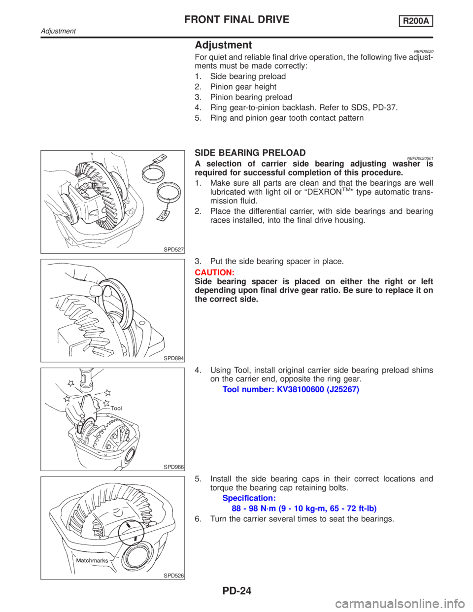
AdjustmentNBPD0020For quiet and reliable final drive operation, the following five adjust-
ments must be made correctly:
1. Side bearing preload
2. Pinion gear height
3. Pinion bearing preload
4. Ring gear-to-pinion backlash. Refer to SDS, PD-37.
5. Ring and pinion gear tooth contact pattern
SPD527
SIDE BEARING PRELOADNBPD0020S01A selection of carrier side bearing adjusting washer is
required for successful completion of this procedure.
1. Make sure all parts are clean and that the bearings are well
lubricated with light oil or ªDEXRON
TMº type automatic trans-
mission fluid.
2. Place the differential carrier, with side bearings and bearing
races installed, into the final drive housing.
SPD894
3. Put the side bearing spacer in place.
CAUTION:
Side bearing spacer is placed on either the right or left
depending upon final drive gear ratio. Be sure to replace it on
the correct side.
SPD986
4. Using Tool, install original carrier side bearing preload shims
on the carrier end, opposite the ring gear.
Tool number: KV38100600 (J25267)
SPD526
5. Install the side bearing caps in their correct locations and
torque the bearing cap retaining bolts.
Specification:
88 - 98 N´m (9 - 10 kg-m, 65 - 72 ft-lb)
6. Turn the carrier several times to seat the bearings.
FRONT FINAL DRIVER200A
Adjustment
PD-24
Page 2054 of 2395

Pinion Head Height NumberAdd or Remove from the Standard
Pinion Height Washer Thickness
Measurement
þ6 Add 0.06 mm (0.0024 in)
þ5 Add 0.05 mm (0.0020 in)
þ4 Add 0.04 mm (0.0016 in)
þ3 Add 0.03 mm (0.0012 in)
þ2 Add 0.02 mm (0.0008 in)
þ1 Add 0.01 mm (0.0004 in)
0 Use the selected washer thickness
+1 Subtract 0.01 mm (0.0004 in)
+2 Subtract 0.02 mm (0.0008 in)
+3 Subtract 0.03 mm (0.0012 in)
+4 Subtract 0.04 mm (0.0016 in)
+5 Subtract 0.05 mm (0.0020 in)
+6 Subtract 0.06 mm (0.0024 in)
SPD205A
16. Remove the J34309 pinion preload shim selector tool from the
final drive housing and disassemble to retrieve the pinion bear-
ings.
TOOTH CONTACTNBPD0020S03Gear tooth contact pattern check is necessary to verify correct
relationship between ring gear and drive pinion.
Hypoid gear sets which are not positioned properly in relation to
one another may be noisy, or have short life, or both. With a pat-
tern check, the most desirable contact for low noise level and long
life can be assured.
SPD357
1. Thoroughly clean ring gear and drive pinion teeth.
2. Sparingly apply a mixture of powdered ferric oxide and oil or
equivalent to 3 or 4 teeth of ring gear drive side.
GI
MA
EM
LC
EC
FE
AT
TF
AX
SU
BR
ST
RS
BT
HA
SC
EL
IDX
FRONT FINAL DRIVER200A
Adjustment (Cont'd)
PD-29