oil INFINITI QX4 2001 Factory Service Manual
[x] Cancel search | Manufacturer: INFINITI, Model Year: 2001, Model line: QX4, Model: INFINITI QX4 2001Pages: 2395, PDF Size: 43.2 MB
Page 2071 of 2395

SPD563
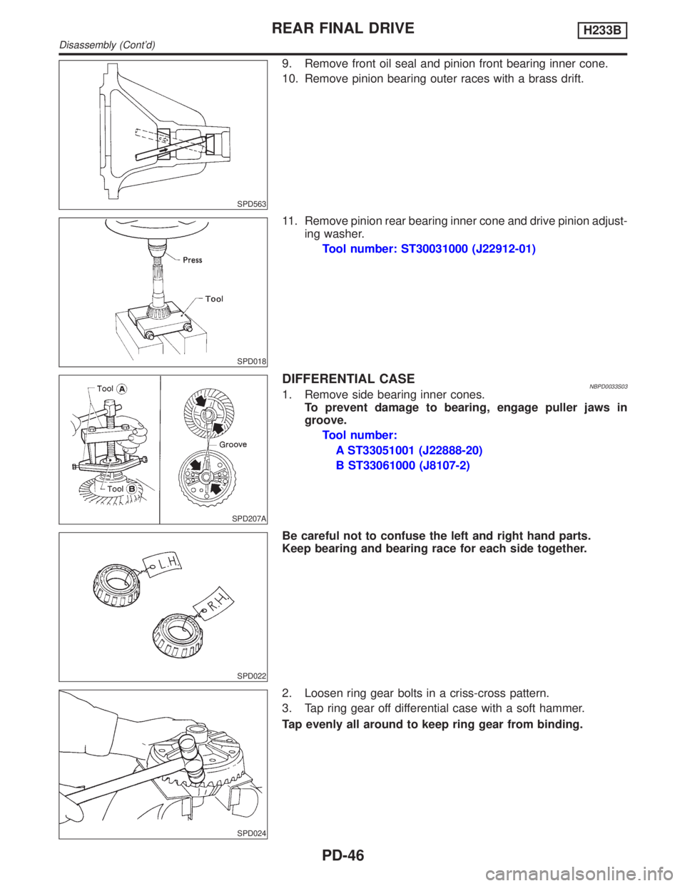
9. Remove front oil seal and pinion front bearing inner cone.
10. Remove pinion bearing outer races with a brass drift.
SPD018
11. Remove pinion rear bearing inner cone and drive pinion adjust-
ing washer.
Tool number: ST30031000 (J22912-01)
SPD207A
DIFFERENTIAL CASENBPD0033S031. Remove side bearing inner cones.
To prevent damage to bearing, engage puller jaws in
groove.
Tool number:
A ST33051001 (J22888-20)
B ST33061000 (J8107-2)
SPD022
Be careful not to confuse the left and right hand parts.
Keep bearing and bearing race for each side together.
SPD024
2. Loosen ring gear bolts in a criss-cross pattern.
3. Tap ring gear off differential case with a soft hammer.
Tap evenly all around to keep ring gear from binding.
REAR FINAL DRIVEH233B
Disassembly (Cont'd)
PD-46
Page 2074 of 2395

SPD359A
INSPECTIONNBPD0037Contact SurfacesNBPD0037S011. Clean the disassembled parts in suitable solvent and blow dry
with compressed air.
2. If following surfaces are found with burrs or scratches, smooth
with oil stone.
1Differential case B
2Differential case A
3Side gear
4Pinion mate gear
5Pinion mate shaft
6Friction plate guide
Disc and PlateNBPD0037S021. Clean the discs and plates in suitable solvent and blow dry with
compressed air.
2. Inspect discs and plates for wear, nicks and burrs.
SPD279
3. To test if friction disc or plate is not distorted, place it on a sur-
face plate and rotate it by hand with indicating finger of dial
gauge resting against disc or plate surface.
Allowable warpage:
0.08 mm (0.0031 in)
If it exceeds limits, replace with a new plate to eliminate pos-
sibility of clutch slippage or sticking.
GI
MA
EM
LC
EC
FE
AT
TF
AX
SU
BR
ST
RS
BT
HA
SC
EL
IDX
REAR FINAL DRIVEH233B
Limited Slip Differential (Cont'd)
PD-49
Page 2076 of 2395

SPD418
3. Measure values of ªCº.
a. Attach a dial indicator to the base plate.
b. Place differential case B on the base plate, and install a mas-
ter gauge on case B.
Then adjust the dial indicator scale to zero with its tip on
the master gauge.
SPD419
c. Install pinion mate gears, side gears and pinion mate shaft in
differential case B.
d. Set dial indicator's tip on the side gear, and read the indication.
Example:
E = A þ D = A þ (B + C) = 0.05 to 0.15 mm
A = 49.52 mm
B = 19.45 mm
C = 29.7 mm
D=B+C
49.15 (D) = 19.45 (B) + 29.7 (C)
E =Aþ D
0.37 (E) = 49.52 (A) þ 49.15 (D)
From the above equation, end play of 0.37 mm exceeds the speci-
fied range of 0.05 to 0.15 mm.
Select suitable discs and plates to adjust correctly.
SPD421
ASSEMBLYNBPD0039Prior to assembling discs and plates, properly lubricate them by
dipping them in limited slip differential oil.
1. Alternately position specified number of friction plates and fric-
tion discs on rear of side gear.
Always position a friction plate first on rear of side gear.
SPD384A
2. Install spring plate.
GI
MA
EM
LC
EC
FE
AT
TF
AX
SU
BR
ST
RS
BT
HA
SC
EL
IDX
REAR FINAL DRIVEH233B
Limited Slip Differential (Cont'd)
PD-51
Page 2077 of 2395

SPD385A
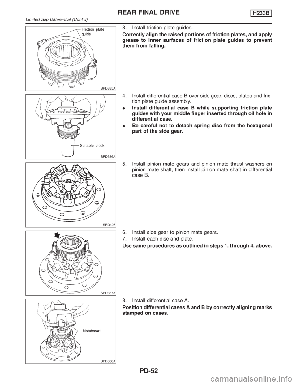
3. Install friction plate guides.
Correctly align the raised portions of friction plates, and apply
grease to inner surfaces of friction plate guides to prevent
them from falling.
SPD386A
4. Install differential case B over side gear, discs, plates and fric-
tion plate guide assembly.
IInstall differential case B while supporting friction plate
guides with your middle finger inserted through oil hole in
differential case.
IBe careful not to detach spring disc from the hexagonal
part of the side gear.
SPD426
5. Install pinion mate gears and pinion mate thrust washers on
pinion mate shaft, then install pinion mate shaft in differential
case B.
SPD387A
6. Install side gear to pinion mate gears.
7. Install each disc and plate.
Use same procedures as outlined in steps 1. through 4. above.
SPD388A
8. Install differential case A.
Position differential cases A and B by correctly aligning marks
stamped on cases.
REAR FINAL DRIVEH233B
Limited Slip Differential (Cont'd)
PD-52
Page 2081 of 2395

SPD220A
13. Remove the J34309 pinion preload shim selector tool from the
final drive housing and disassemble to retrieve the pinion bear-
ings.
TOOTH CONTACTNBPD0040S02Gear tooth contact pattern check is necessary to verify correct
relationship between ring gear and drive pinion.
Hypoid gear sets which are not positioned properly in relation to
one another may be noisy, or have short life or both. With a pat-
tern check, the most desirable contact for low noise level and long
life can be assured.
SPD005
1. Thoroughly clean ring gear and drive pinion teeth.
2. Sparingly apply a mixture of powdered ferric oxide and oil or
equivalent to 3 or 4 teeth of ring gear drive side.
SPD695
3. Hold companion flange steady by hand and rotate the ring gear
in both directions.
REAR FINAL DRIVEH233B
Adjustment (Cont'd)
PD-56
Page 2083 of 2395

SPD322
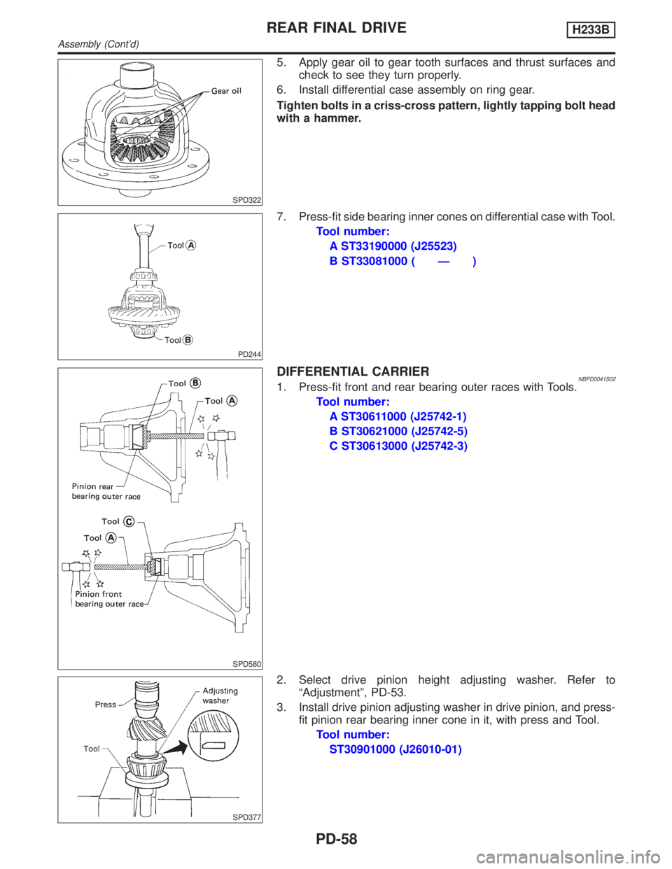
5. Apply gear oil to gear tooth surfaces and thrust surfaces and
check to see they turn properly.
6. Install differential case assembly on ring gear.
Tighten bolts in a criss-cross pattern, lightly tapping bolt head
with a hammer.
PD244
7. Press-fit side bearing inner cones on differential case with Tool.
Tool number:
A ST33190000 (J25523)
B ST33081000 ( Ð )
SPD580
DIFFERENTIAL CARRIERNBPD0041S021. Press-fit front and rear bearing outer races with Tools.
Tool number:
A ST30611000 (J25742-1)
B ST30621000 (J25742-5)
C ST30613000 (J25742-3)
SPD377
2. Select drive pinion height adjusting washer. Refer to
ªAdjustmentº, PD-53.
3. Install drive pinion adjusting washer in drive pinion, and press-
fit pinion rear bearing inner cone in it, with press and Tool.
Tool number:
ST30901000 (J26010-01)
REAR FINAL DRIVEH233B
Assembly (Cont'd)
PD-58
Page 2084 of 2395

SPD581
4. Place pinion front bearing inner cone in gear carrier.
SPD291A
5. Apply multi-purpose grease to cavity at sealing lips of oil seal.
Install front oil seal.
Tool number:
A ST30720000 (J25405)
B KV38102510 ( Ð )
SPD935-A
6. Install drive pinion bearing spacer, pinion bearing adjusting
shim and drive pinion in gear carrier.
SPD697
7. Insert companion flange into drive pinion by tapping the com-
panion flange with a soft hammer.
SPD481A
8. Tighten pinion nut to the specified torque.
The threaded portion of drive pinion and pinion nut should be
free from oil or grease.
Tool number: KV38108300 (J44195)
GI
MA
EM
LC
EC
FE
AT
TF
AX
SU
BR
ST
RS
BT
HA
SC
EL
IDX
REAR FINAL DRIVEH233B
Assembly (Cont'd)
PD-59
Page 2085 of 2395

SPD149
SPD684
9. Turn drive pinion in both directions several times, and measure
pinion bearing preload.
Tool number: ST3127S000 (J25765-A)
Pinion bearing preload (Without front oil seal):
1.2 - 2.0 N´m (12 - 20 kg-cm, 10 - 17 in-lb)
If preload is out of specification, adjust the thickness of spacer and
shim combination by replacing shim and spacer with thinner one.
IStart from the combination of thickest spacer and shim.
ICombine each spacer and shim thickness one by one until the
correct specification are achieved.
Drive pinion bearing preload adjusting spacer and
shim:
Refer to SDS, PD-64.
10. Install differential case assembly with side bearing outer races
into gear carrier.
11. Position side bearing adjusters on gear carrier with threads
properly engaged; screw in adjusters lightly at this stage of
assembly.
Tool number: ST32580000 (J34312)
SPD265
12. Align mark on bearing cap with that on gear carrier and install
bearing cap on gear carrier.
IDo not tighten at this point to allow further tightening of side
bearing adjusters.
SPD246
13. Tighten both right and left side bearing adjusters alternately
and measure ring gear backlash and total preload at the same
time. Adjust right and left side bearing adjusters by tightening
them alternately so that proper ring gear backlash and total
preload can be obtained.
Ring gear-to-drive pinion backlash:
0.13 - 0.18 mm (0.0051 - 0.0071 in)
SPD149
IWhen checking preload, turn drive pinion in both direc-
tions several times to set bearing rollers.
Tool number: ST3127S000 (J25765-A)
Total preload:
P
1+ [0.3 - 0.4 N´m (3 - 4 kg-cm, 2.6 - 3.5 in-lb)]
P
1: Drive pinion preload
REAR FINAL DRIVEH233B
Assembly (Cont'd)
PD-60
Page 2087 of 2395

Service Data and Specifications (SDS)
H233B=NBPD0042General SpecificationsNBPD0042S01
Rear final drive2WD 4WD
Standard Optional
H233B
2-pinion LSD
Gear ratio4.363
Number of teeth (Ring gear/drive pinion) 48/11
Oil capacity (Approx.)(US pt, lmp pt) 2.8 (5-7/8, 4-7/8)
Ring Gear RunoutNBPD0042S02
Ring gear runout limit mm (in)0.08 (0.0031)
Side Gear AdjustmentNBPD0042S03
Side gear backlash (Clearance between side gear and differential case) mm (in) 0.10 - 0.20 (0.0039 - 0.0079)
Available side
gear thrust
washersThickness mm (in) Part number*
1.75 (0.0689)
1.80 (0.0709)
1.85 (0.0728)38424-T5000
38424-T5001
38424-T5002
*: Always check with the Parts Department for the latest parts information.
Differential Torque Adjustment (LSD models)NBPD0042S04
Differential torque N´m (kg-m, ft-lb) 88 - 108 (9 - 11, 65 - 80)
Number of discs and plates (One
side)Friction disc 2
Friction plate 9
Spring plate 2
Wear limit of plate and disc mm (in) 0.1 (0.004)
Allowable warpage of friction disc and plate mm (in) 0.08 (0.0031)
Available discs
and platesPlate name Thickness mm (in) Part number*
Friction disc1.48 - 1.52 (0.0583 - 0.0598)
1.38 - 1.42 (0.0543 - 0.0559)
1.58 - 1.62 (0.0622 - 0.0638)38433-C6002 (Standard type)
38433-C6004 (Adjusting type)
38433-C6003 (Adjusting type)
Friction plate1.48 - 1.52 (0.0583 - 0.0598)
1.38 - 1.42 (0.0543 - 0.0559)
1.58 - 1.62 (0.0622 - 0.0638)38432-C6001
38432-C6002
38432-C6003
Spring plate 1.48 - 1.52 (0.0583 - 0.0598) 38435-S9200
*: Always check with the Parts Department for the latest parts information.
Total Preload AdjustmentNBPD0042S05
Total preload N´m (kg-cm, in-lb) P1+ [0.3 - 0.4 (3 - 4, 2.6 - 3.5)]
Ring gear backlash mm (in) 0.13 - 0.18 (0.0051 - 0.0071)
Side bearing adjusting methodSide adjuster
P1: Drive pinion preload
REAR FINAL DRIVEH233B
Service Data and Specifications (SDS)
PD-62
Page 2089 of 2395
![INFINITI QX4 2001 Factory Service Manual Drive Pinion Preload Adjustment=NBPD0042S07
Drive pinion bearing preload adjusting method Adjusting shim and spacer
Drive pinion preload without front oil seal N´m (kg-cm, in-lb) [P
1] 1.2 - 2.0 (12 INFINITI QX4 2001 Factory Service Manual Drive Pinion Preload Adjustment=NBPD0042S07
Drive pinion bearing preload adjusting method Adjusting shim and spacer
Drive pinion preload without front oil seal N´m (kg-cm, in-lb) [P
1] 1.2 - 2.0 (12](/img/42/57027/w960_57027-2088.png)
Drive Pinion Preload Adjustment=NBPD0042S07
Drive pinion bearing preload adjusting method Adjusting shim and spacer
Drive pinion preload without front oil seal N´m (kg-cm, in-lb) [P
1] 1.2 - 2.0 (12 - 20, 10 - 17)
Available front
drive pinion
bearing adjust-
ing shimsThickness mm (in) Part number*
2.31 (0.0909)
2.33 (0.0917)
2.35 (0.0925)
2.37 (0.0933)
2.39 (0.0941)
2.41 (0.0949)
2.43 (0.0957)
2.45 (0.0965)
2.47 (0.0972)
2.49 (0.0980)
2.51 (0.0988)
2.53 (0.0996)
2.55 (0.1004)
2.57 (0.1012)
2.59 (0.1020)38125-82100
38126-82100
38127-82100
38128-82100
38129-82100
38130-82100
38131-82100
38132-82100
38133-82100
38134-82100
38135-82100
38136-82100
38137-82100
38138-82100
38139-82100
Available drive
pinion bearing
adjusting spac-
ersThickness mm (in) Part number*
4.50 (0.1772)
4.75 (0.1870)
5.00 (0.1969)
5.25 (0.2067)
5.50 (0.2165)38165-76000
38166-76000
38167-76000
38166-01J00
38166-01J10
*: Always check with the Parts Department for the latest parts information.
REAR FINAL DRIVEH233B
Service Data and Specifications (SDS) (Cont'd)
PD-64