oil level INFINITI QX4 2001 Factory Owner's Manual
[x] Cancel search | Manufacturer: INFINITI, Model Year: 2001, Model line: QX4, Model: INFINITI QX4 2001Pages: 2395, PDF Size: 43.2 MB
Page 1259 of 2395

SEL350X
Aiming AdjustmentNBEL0029Before performing aiming adjustment, make sure of the following.
1) Keep all tires inflated to correct pressure.
2) Place vehicle on level ground.
3) See that vehicle is unloaded (except for full levels of coolant,
engine oil and fuel, and spare tire, jack, and tools). Have the
driver or equivalent weight placed in driver's seat.
Adjust aiming in the vertical direction by turning the adjusting
screw.
MEL327G
1. Set the distance between the screen and the center of the fog
lamp lens as shown at left.
2. Turn front fog lamps ON.
MEL328GA
3. Adjust front fog lamps so that the top edge of the high inten-
sity zone is 200 mm (7.9 in) below the height of the fog lamp
centers as shown at left.
IWhen performing adjustment, if necessary, cover the head-
lamps and opposite fog lamp.
FRONT FOG LAMP
Aiming Adjustment
EL-74
Page 1307 of 2395

SEL062WA
Fuel Warning Lamp Sensor CheckNBEL01661. Turn ignition switch ªOFFº.
2. Disconnect fuel level sensor unit harness connector B12.
3. Connect a resistor (80W) between fuel tank gauge unit harness
connector terminals 2 and 3.
4. Turn ignition switch ªONº.
The fuel warning lamp should come on.
NOTE:
ECM might store the 1st trip DTC P0180 during this inspection.
If the DTC is stored in ECM memory, erase the DTC after recon-
necting fuel tank gauge unit harness connector.
Refer to EC-60, ªHOW TO ERASE EMISSION-RELATED DIAG-
NOSTIC INFORMATIONº.
MEL425F
Electrical Components InspectionNBEL0051OIL PRESSURE SWITCH CHECKNBEL0051S02
Oil pressure
kPa (kg/cm2, psi)Continuity
Engine startMore than 10 - 20
(0.1-0.2,1-3)NO
Engine stopLess than 10 - 20
(0.1-0.2,1-3)YES
Check the continuity between the terminals of oil pressure switch
and body ground.
SEL901F
DIODE CHECKNBEL0051S03ICheck continuity using an ohmmeter.
IDiode is functioning properly if test results are as shown in the
figure at left.
ICheck diodes at the combination meter harness connector
instead of checking them on the combination meter assembly.
Refer to EL-115, ªWARNING LAMPº wiring diagrams.
NOTE:
Specification may vary depending on the type of tester. Before
performing this inspection, be sure to refer to the instruction
manual for the tester to be used.
WARNING LAMPS
Fuel Warning Lamp Sensor Check
EL-122
Page 1658 of 2395
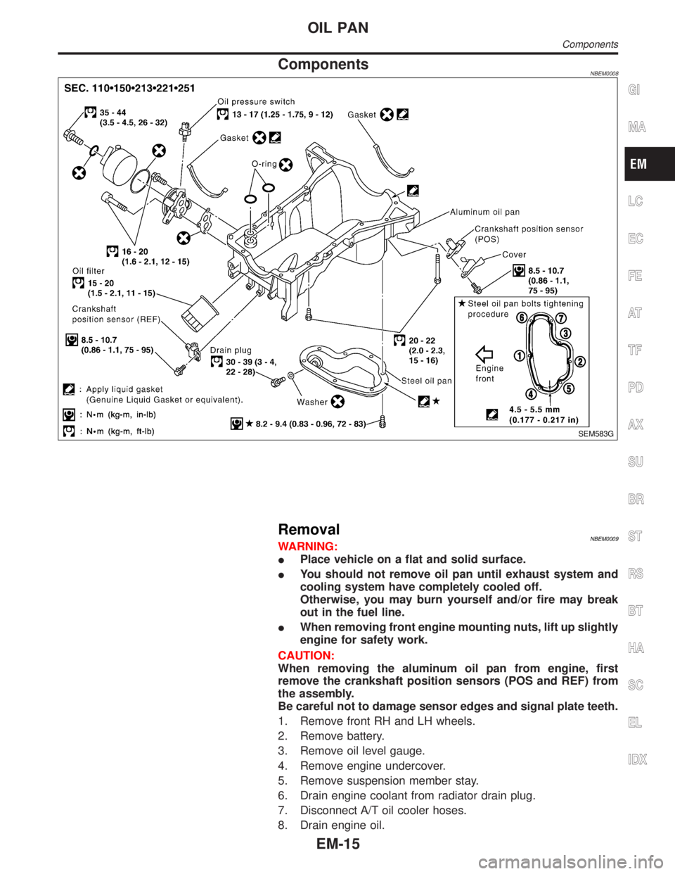
ComponentsNBEM0008
SEM583G
RemovalNBEM0009WARNING:
IPlace vehicle on a flat and solid surface.
IYou should not remove oil pan until exhaust system and
cooling system have completely cooled off.
Otherwise, you may burn yourself and/or fire may break
out in the fuel line.
IWhen removing front engine mounting nuts, lift up slightly
engine for safety work.
CAUTION:
When removing the aluminum oil pan from engine, first
remove the crankshaft position sensors (POS and REF) from
the assembly.
Be careful not to damage sensor edges and signal plate teeth.
1. Remove front RH and LH wheels.
2. Remove battery.
3. Remove oil level gauge.
4. Remove engine undercover.
5. Remove suspension member stay.
6. Drain engine coolant from radiator drain plug.
7. Disconnect A/T oil cooler hoses.
8. Drain engine oil.
GI
MA
LC
EC
FE
AT
TF
PD
AX
SU
BR
ST
RS
BT
HA
SC
EL
IDX
OIL PAN
Components
EM-15
Page 1751 of 2395
IClean all disassembled parts in the designated liquid or solvent
prior to inspection or assembly.
IReplace oil seals, gaskets, packings, O-rings, locking washers,
cotter pins, self-locking nuts, etc. with new ones.
IReplace inner and outer races of tapered roller bearings and
needle bearings as a set.
IArrange the disassembled parts in accordance with their
assembled locations and sequence.
IDo not touch the terminals of electrical components which use
microcomputers (such as ECMs).
Static electricity may damage internal electronic components.
IAfter disconnecting vacuum or air hoses, attach a tag to indi-
cate the proper connection.
IUse only the fluids and lubricants specified in this manual.
IUse approved bonding agent, sealants or their equivalents
when required.
IUse tools and recommended special tools where specified for
safe and efficient service repairs.
IWhen repairing the fuel, oil, water, vacuum or exhaust
systems, check all affected lines for leaks.
IDispose of drained oil or the solvent used for cleaning parts in
an appropriate manner.
WARNING:
To prevent ECM from storing the diagnostic trouble codes, do
not carelessly disconnect the harness connectors which are
related to the engine control system and TCM (Transmission
Control Module) system. The connectors should be discon-
nected only when working according to the WORK FLOW of
TROUBLE DIAGNOSES in EC and AT sections.
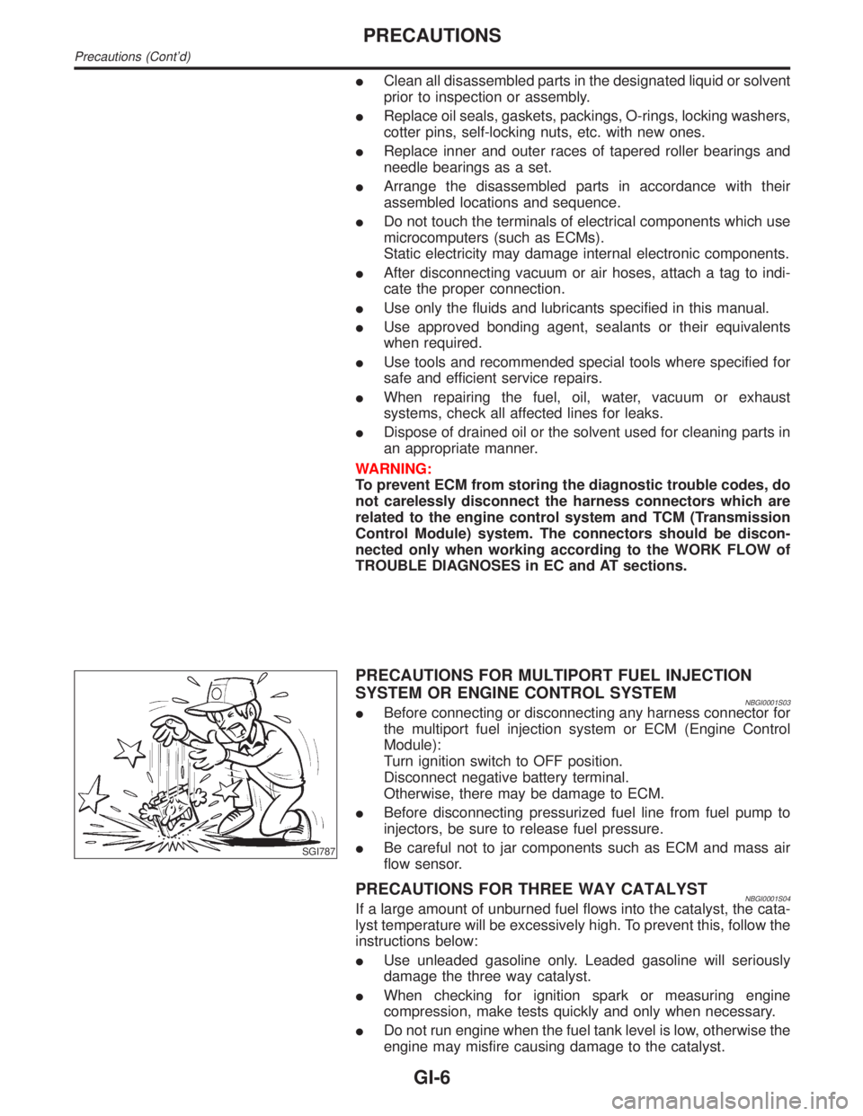
SGI787
PRECAUTIONS FOR MULTIPORT FUEL INJECTION
SYSTEM OR ENGINE CONTROL SYSTEM
NBGI0001S03IBefore connecting or disconnecting any harness connector for
the multiport fuel injection system or ECM (Engine Control
Module):
Turn ignition switch to OFF position.
Disconnect negative battery terminal.
Otherwise, there may be damage to ECM.
IBefore disconnecting pressurized fuel line from fuel pump to
injectors, be sure to release fuel pressure.
IBe careful not to jar components such as ECM and mass air
flow sensor.
PRECAUTIONS FOR THREE WAY CATALYSTNBGI0001S04If a large amount of unburned fuel flows into the catalyst, the cata-
lyst temperature will be excessively high. To prevent this, follow the
instructions below:
IUse unleaded gasoline only. Leaded gasoline will seriously
damage the three way catalyst.
IWhen checking for ignition spark or measuring engine
compression, make tests quickly and only when necessary.
IDo not run engine when the fuel tank level is low, otherwise the
engine may misfire causing damage to the catalyst.
PRECAUTIONS
Precautions (Cont'd)
GI-6
Page 1813 of 2395
Refrigeration System
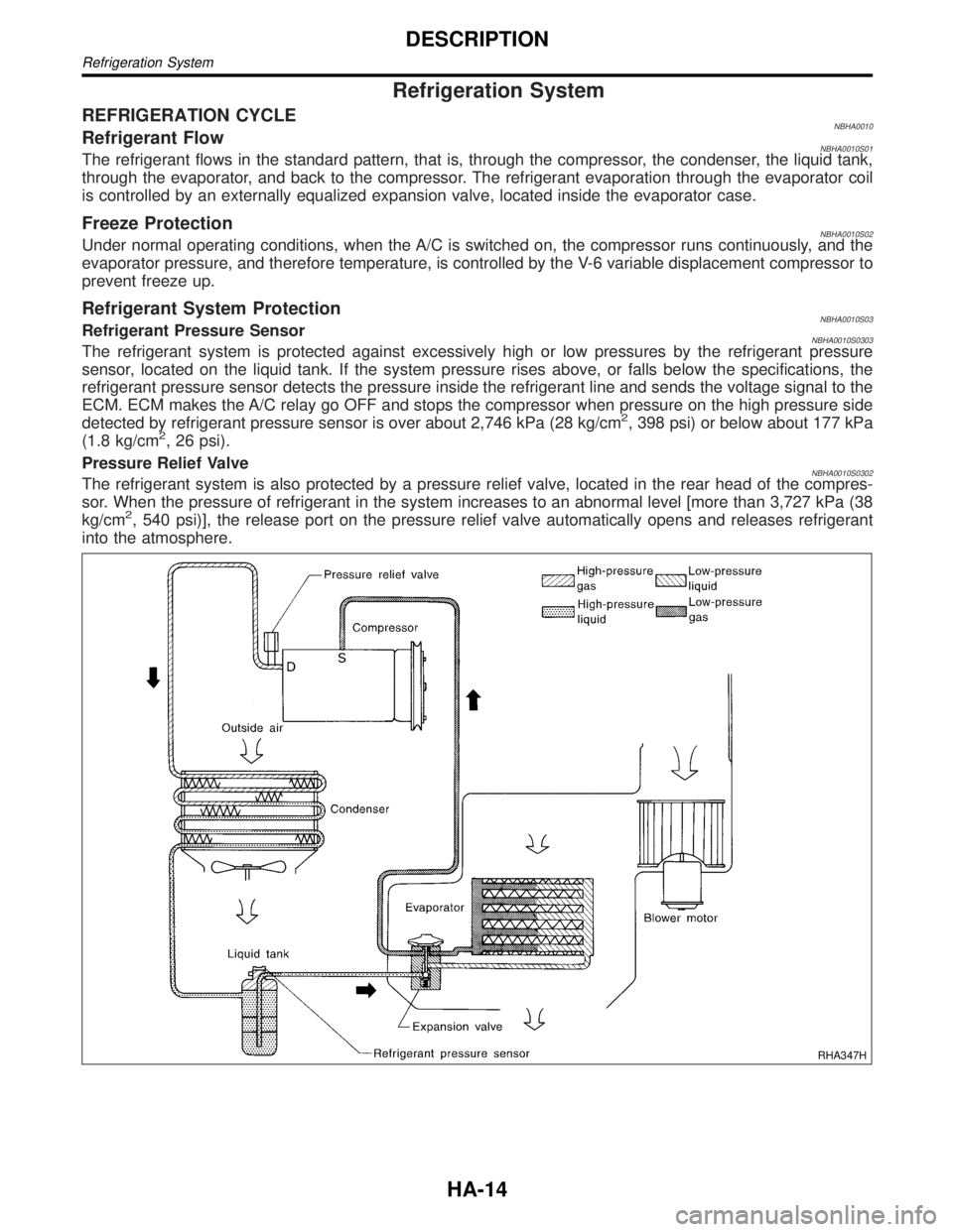
REFRIGERATION CYCLENBHA0010Refrigerant FlowNBHA0010S01The refrigerant flows in the standard pattern, that is, through the compressor, the condenser, the liquid tank,
through the evaporator, and back to the compressor. The refrigerant evaporation through the evaporator coil
is controlled by an externally equalized expansion valve, located inside the evaporator case.
Freeze ProtectionNBHA0010S02Under normal operating conditions, when the A/C is switched on, the compressor runs continuously, and the
evaporator pressure, and therefore temperature, is controlled by the V-6 variable displacement compressor to
prevent freeze up.
Refrigerant System ProtectionNBHA0010S03Refrigerant Pressure SensorNBHA0010S0303The refrigerant system is protected against excessively high or low pressures by the refrigerant pressure
sensor, located on the liquid tank. If the system pressure rises above, or falls below the specifications, the
refrigerant pressure sensor detects the pressure inside the refrigerant line and sends the voltage signal to the
ECM. ECM makes the A/C relay go OFF and stops the compressor when pressure on the high pressure side
detected by refrigerant pressure sensor is over about 2,746 kPa (28 kg/cm
2, 398 psi) or below about 177 kPa
(1.8 kg/cm2, 26 psi).
Pressure Relief Valve
NBHA0010S0302The refrigerant system is also protected by a pressure relief valve, located in the rear head of the compres-
sor. When the pressure of refrigerant in the system increases to an abnormal level [more than 3,727 kPa (38
kg/cm
2, 540 psi)], the release port on the pressure relief valve automatically opens and releases refrigerant
into the atmosphere.
RHA347H
DESCRIPTION
Refrigeration System
HA-14
Page 1945 of 2395
Maintenance of Lubricant Quantity in
Compressor
NBHA0071The lubricant in the compressor circulates through the system with
the refrigerant. Add lubricant to compressor when replacing any
component or after a large gas leakage occurred. It is important to
maintain the specified amount.
If lubricant quantity is not maintained properly, the following mal-
functions may result:
ILack of lubricant: May lead to a seized compressor
IExcessive lubricant: Inadequate cooling (thermal exchange
interference)
LUBRICANTNBHA0071S01Name: Nissan A/C System Oil Type S
Part number: KLH00-PAGS0
CHECKING AND ADJUSTINGNBHA0071S02Adjust the lubricant quantity according to the test group shown
below.
1 CHECK LUBRICANT RETURN OPERATION
Can lubricant return operation be performed?
IA/C system works properly.
IThere is no evidence of a large amount of lubricant leakage.
YesorNo
Ye s©GO TO 2.
No©GO TO 3.
2 PERFORM LUBRICANT RETURN OPERATION, PROCEEDING AS FOLLOWS:
1. Start engine, and set the following conditions:
ITest condition
Engine speed: Idling to 1,200 rpm
A/C or AUTO switch: ON
Blower speed: Max. position
Temp. control: Optional [Set so that intake air temperature is 25 to 30ÉC (77 to 86ÉF).]
2.Next item is for V-5 or V-6 compressor. Connect the manifold gauge, and check that the high pressure side
pressure is 588 kPa (6 kg/cm
2, 85 psi) or higher.
If less than the reference level, attach a cover to the front face of the condenser to raise the pressure.
3. Perform lubricant return operation for about 10 minutes.
4. Stop engine.
CAUTION:
If excessive lubricant leakage is noted, do not perform the lubricant return operation.
OK©GO TO 3.
3 CHECK COMPRESSOR
Should the compressor be replaced?
YesorNo
Ye s©Go to ªLubricant Adjustment Procedure for Compressor Replacementº, (HA-148).
No©GO TO 4.
SERVICE PROCEDURE
Maintenance of Lubricant Quantity in Compressor
HA-146
Page 1962 of 2395
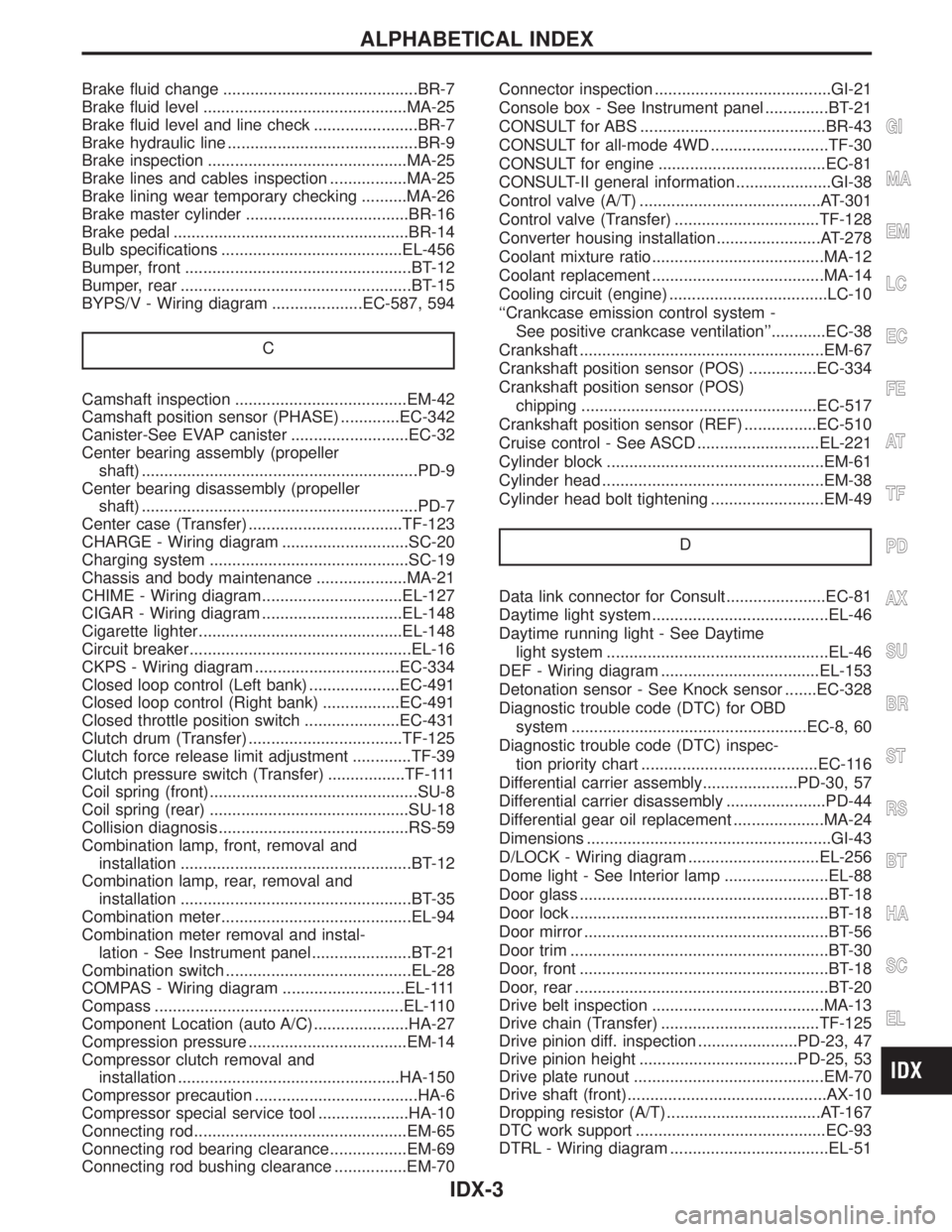
Brake fluid change ...........................................BR-7
Brake fluid level .............................................MA-25
Brake fluid level and line check .......................BR-7
Brake hydraulic line ..........................................BR-9
Brake inspection ............................................MA-25
Brake lines and cables inspection .................MA-25
Brake lining wear temporary checking ..........MA-26
Brake master cylinder ....................................BR-16
Brake pedal ....................................................BR-14
Bulb specifications ........................................EL-456
Bumper, front ..................................................BT-12
Bumper, rear ...................................................BT-15
BYPS/V - Wiring diagram ....................EC-587, 594
C
Camshaft inspection ......................................EM-42
Camshaft position sensor (PHASE) .............EC-342
Canister-See EVAP canister ..........................EC-32
Center bearing assembly (propeller
shaft) .............................................................PD-9
Center bearing disassembly (propeller
shaft) .............................................................PD-7
Center case (Transfer) ..................................TF-123
CHARGE - Wiring diagram ............................SC-20
Charging system ............................................SC-19
Chassis and body maintenance ....................MA-21
CHIME - Wiring diagram...............................EL-127
CIGAR - Wiring diagram ...............................EL-148
Cigarette lighter.............................................EL-148
Circuit breaker.................................................EL-16
CKPS - Wiring diagram ................................EC-334
Closed loop control (Left bank) ....................EC-491
Closed loop control (Right bank) .................EC-491
Closed throttle position switch .....................EC-431
Clutch drum (Transfer) ..................................TF-125
Clutch force release limit adjustment .............TF-39
Clutch pressure switch (Transfer) .................TF-111
Coil spring (front)..............................................SU-8
Coil spring (rear) ............................................SU-18
Collision diagnosis..........................................RS-59
Combination lamp, front, removal and
installation ...................................................BT-12
Combination lamp, rear, removal and
installation ...................................................BT-35
Combination meter..........................................EL-94
Combination meter removal and instal-
lation - See Instrument panel ......................BT-21
Combination switch .........................................EL-28
COMPAS - Wiring diagram ...........................EL-111
Compass .......................................................EL-110
Component Location (auto A/C).....................HA-27
Compression pressure ...................................EM-14
Compressor clutch removal and
installation .................................................HA-150
Compressor precaution ....................................HA-6
Compressor special service tool ....................HA-10
Connecting rod...............................................EM-65
Connecting rod bearing clearance.................EM-69
Connecting rod bushing clearance ................EM-70Connector inspection .......................................GI-21
Console box - See Instrument panel ..............BT-21
CONSULT for ABS .........................................BR-43
CONSULT for all-mode 4WD ..........................TF-30
CONSULT for engine .....................................EC-81
CONSULT-II general information .....................GI-38
Control valve (A/T) ........................................AT-301
Control valve (Transfer) ................................TF-128
Converter housing installation .......................AT-278
Coolant mixture ratio......................................MA-12
Coolant replacement ......................................MA-14
Cooling circuit (engine) ...................................LC-10
``Crankcase emission control system -
See positive crankcase ventilation''............EC-38
Crankshaft ......................................................EM-67
Crankshaft position sensor (POS) ...............EC-334
Crankshaft position sensor (POS)
chipping ....................................................EC-517
Crankshaft position sensor (REF) ................EC-510
Cruise control - See ASCD ...........................EL-221
Cylinder block ................................................EM-61
Cylinder head .................................................EM-38
Cylinder head bolt tightening .........................EM-49
D
Data link connector for Consult......................EC-81
Daytime light system.......................................EL-46
Daytime running light - See Daytime
light system .................................................EL-46
DEF - Wiring diagram ...................................EL-153
Detonation sensor - See Knock sensor .......EC-328
Diagnostic trouble code (DTC) for OBD
system ....................................................EC-8, 60
Diagnostic trouble code (DTC) inspec-
tion priority chart .......................................EC-116
Differential carrier assembly.....................PD-30, 57
Differential carrier disassembly ......................PD-44
Differential gear oil replacement ....................MA-24
Dimensions ......................................................GI-43
D/LOCK - Wiring diagram .............................EL-256
Dome light - See Interior lamp .......................EL-88
Door glass .......................................................BT-18
Door lock .........................................................BT-18
Door mirror ......................................................BT-56
Door trim .........................................................BT-30
Door, front .......................................................BT-18
Door, rear ........................................................BT-20
Drive belt inspection ......................................MA-13
Drive chain (Transfer) ...................................TF-125
Drive pinion diff. inspection ......................PD-23, 47
Drive pinion height ...................................PD-25, 53
Drive plate runout ..........................................EM-70
Drive shaft (front)............................................AX-10
Dropping resistor (A/T) ..................................AT-167
DTC work support ..........................................EC-93
DTRL - Wiring diagram ...................................EL-51
GI
MA
EM
LC
EC
FE
AT
TF
PD
AX
SU
BR
ST
RS
BT
HA
SC
EL
ALPHABETICAL INDEX
IDX-3
Page 1965 of 2395

LSV (Load sensing valve) ..............................BR-12
Lubricant (R134a) A/C..................................HA-146
Lubricants .......................................................MA-11
Lubrication circuit (engine) ...............................LC-3
Lubrication-locks, hinges and hood
latches ........................................................MA-27
Luggage room lamp ........................................EL-88
M
MAFS - Wiring diagram................................EC-154
Magnet clutch .......................................HA-104, 150
MAIN - Wiring diagram.................................EC-142
Main oil pump (Transfer)...............................TF-131
Mainshaft (Transfer) ......................................TF-125
Maintenance (engine) ....................................MA-13
MAJOR OVERHALL......................................AT-281
Major overhaul (Transfer) .............................TF-120
Malfunction indicator lamp (MIL) ....................EC-74
Mass air flow sensor (MAFS) .......................EC-150
Master cylinder (brake) ..................................BR-16
Meter ...............................................................EL-94
METER - Wiring diagram................................EL-99
MIL & Data link connectors circuit ...............EC-648
MIL/DL - Wiring diagram ..............................EC-648
MIRROR - Wiring diagram............................EL-177
Mirror defogger .............................................EL-151
Mirror, door......................................................BT-56
Mirror, out side ................................................BT-56
Misfire ...........................................................EC-320
Mode door control linkage adjustment ...........HA-81
Mode door motor ............................................HA-75
Model variation ................................................GI-41
Molding - See Exterior ....................................BT-35
MULTI - Wiring diagram ................................EL-274
Multi-remote control system..........................EL-270
Multiplex communication ..............................HA-142
Multiport fuel injection (MFI) system ..............EC-28
Multiport fuel injection precautions ....................GI-6
N
NATS (Nissan anti-theft system)...................EL-328
NATS (Nissan anti-theft system)
precautions ....................................................GI-3
NATS - Wiring diagram .................................EL-330
NAVI - wiring diagram ...................................EL-394
Navigation System ........................................EL-385
Neutral-4LO switch ........................................TF-112
NVH troubleshooting (AX) ..........................AX-3, 18
NVH troubleshooting (BR)................................BR-6
NVH troubleshooting (PD)................................PD-3
NVH troubleshooting (ST).................................ST-6
NVH troubleshooting (SU) .........................SU-3, 15O
Oil change (capacity) .....................................MA-11
Oil filter (Transfer) .........................................TF-118
Oil pan (engine) .............................................EM-15
Oil pressure (engine) ........................................LC-4
Oil pump (A/T) ...............................................AT-297
Oil pump (engine) .............................................LC-5
Oil pump regulator valve (engine) ....................LC-6
Oil seal replacement (engine)........................EM-35
Oil seal replacement (front final drive
4WD) ...........................................................PD-15
Oil seal replacement (front of final
drive) ...........................................................PD-40
On board diagnostic system ..........................EC-59
Out side mirror ................................................BT-56
Overdrive control switch ................................AT-263
Overrun clutch ...............................................AT-320
Overrun clutch solenoid valve .......................AT-189
P
P/ANT - Wiring diagram ................................EL-170
Park/Neutral position switch .........................EC-604
Park/neutral position switch (A/T) .........AT-103, 263
Parking brake control .....................................BR-30
Parking lamp ...................................................EL-61
PCV (positive crankcase ventilation) .............EC-38
PGC/V - Wiring diagram ......................EC-370, 544
PHASE - Wiring diagram .............................EC-342
Pinion bearing preload diff. ............................PD-25
Pinion gear height diff. .............................PD-25, 53
Piston assembly .............................................EM-71
Piston pin inspection ......................................EM-63
Piston ring inspection.....................................EM-64
Piston to bore clearance ................................EM-66
Planetary carrier (Transfer) ...........................TF-134
PNP/SW - Wiring diagram ...........................EC-607
POS - Wiring diagram ..................................EC-517
POWER - Wiring diagram...............................EL-10
Power antenna ..............................................EL-169
Power door lock ............................................EL-254
Power door mirror .........................................EL-177
Power seat ....................................................EL-181
Power steering fluid level .....................MA-27, ST-8
Power steering gear........................................ST-17
Power steering hydraulic pressure .................ST-10
Power steering oil pressure switch ..............EC-634
Power steering oil pump .................................ST-27
Power steering system bleeding.......................ST-9
Power supply routing ........................................EL-9
Power transistor & ignition coil.....................EC-499
Power window ...............................................EL-241
PRE/SE - Wiring diagram ............................EC-384
Precations for Leak detection dye ...................HA-3
Precautions (General) .......................................GI-5
Pressure test (A/T) ..........................................AT-62
Propeller shaft ..................................................PD-3
ALPHABETICAL INDEX
IDX-6
Page 1973 of 2395
SLC351BA
SLC322B
SLC926
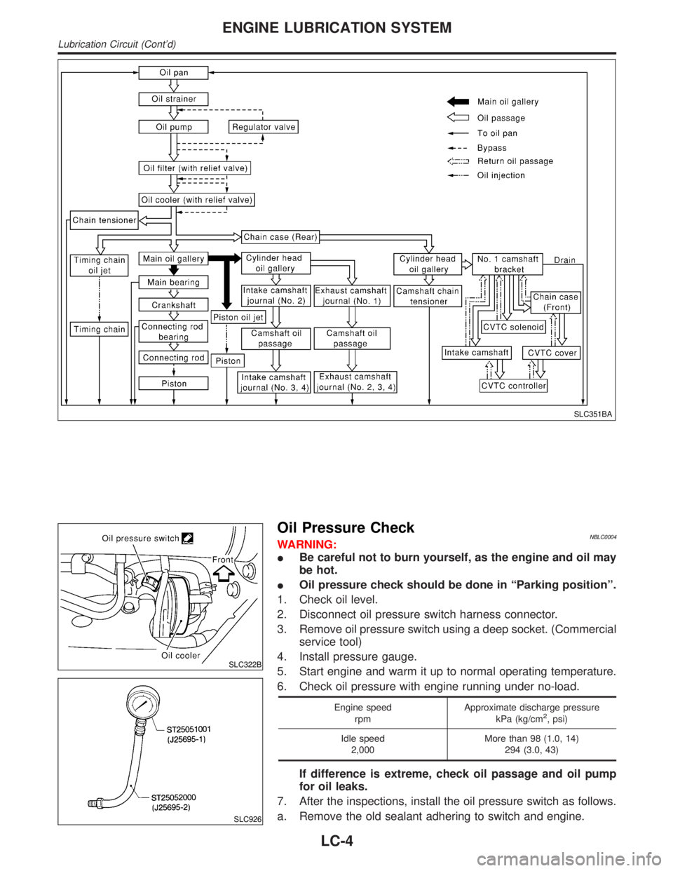
Oil Pressure CheckNBLC0004WARNING:
IBe careful not to burn yourself, as the engine and oil may
be hot.
IOil pressure check should be done in ªParking positionº.
1. Check oil level.
2. Disconnect oil pressure switch harness connector.
3. Remove oil pressure switch using a deep socket. (Commercial
service tool)
4. Install pressure gauge.
5. Start engine and warm it up to normal operating temperature.
6. Check oil pressure with engine running under no-load.
Engine speed
rpmApproximate discharge pressure
kPa (kg/cm2, psi)
Idle speed
2,000More than 98 (1.0, 14)
294 (3.0, 43)
If difference is extreme, check oil passage and oil pump
for oil leaks.
7. After the inspections, install the oil pressure switch as follows.
a. Remove the old sealant adhering to switch and engine.
ENGINE LUBRICATION SYSTEM
Lubrication Circuit (Cont'd)
LC-4
Page 1996 of 2395
MAINTENANCE
SECTION
MA
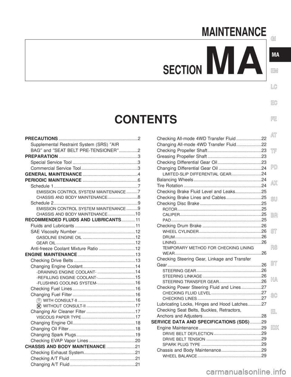
CONTENTS
PRECAUTIONS...............................................................2
Supplemental Restraint System (SRS)²AIR
BAG²and²SEAT BELT PRE-TENSIONER²...............2
PREPARATION...............................................................3
Special Service Tool ....................................................3
Commercial Service Tool .............................................3
GENERAL MAINTENANCE............................................4
PERIODIC MAINTENANCE............................................6
Schedule 1 ...................................................................7
EMISSION CONTROL SYSTEM MAINTENANCE.........7
CHASSIS AND BODY MAINTENANCE........................8
Schedule 2 ...................................................................9
EMISSION CONTROL SYSTEM MAINTENANCE.........9
CHASSIS AND BODY MAINTENANCE......................10
RECOMMENDED FLUIDS AND LUBRICANTS........... 11
Fluids and Lubricants ................................................ 11
SAE Viscosity Number ..............................................12
GASOLINE ENGINE OIL..........................................12
GEAR OIL...............................................................12
Anti-freeze Coolant Mixture Ratio .............................12
ENGINE MAINTENANCE..............................................13
Checking Drive Belts .................................................13
Changing Engine Coolant..........................................14
-DRAINING ENGINE COOLANT-..............................14
-REFILLING ENGINE COOLANT-..............................15
-FLUSHING COOLING SYSTEM-..............................16
Checking Fuel Lines ..................................................16
Changing Fuel Filter ..................................................16
WITH CONSULT-II..............................................16
WITHOUT CONSULT-II.......................................17
Changing Air Cleaner Filter .......................................17
VISCOUS PAPER TYPE...........................................17
Changing Engine Oil..................................................18
Changing Oil Filter .....................................................18
Changing Spark Plugs ...............................................19
Checking EVAP Vapor Lines .....................................20
CHASSIS AND BODY MAINTENANCE.......................21
Checking Exhaust System.........................................21
Checking A/T Fluid ....................................................21
Changing A/T Fluid ....................................................21Checking All-mode 4WD Transfer Fluid ....................22
Changing All-mode 4WD Transfer Fluid ....................22
Checking Propeller Shaft ...........................................23
Greasing Propeller Shaft ...........................................23
Checking Differential Gear Oil ...................................23
Changing Differential Gear Oil ..................................24
LIMITED-SLIP DIFFERENTIAL GEAR........................24
Balancing Wheels ......................................................24
Tire Rotation ..............................................................24
Checking Brake Fluid Level and Leaks.....................25
Checking Brake Lines and Cables ............................25
Checking Disc Brake .................................................25
ROTOR...................................................................25
CALIPER.................................................................25
PAD........................................................................25
Checking Drum Brake ...............................................26
WHEEL CYLINDER..................................................26
DRUM.....................................................................26
LINING....................................................................26
TEMPORARY METHOD FOR CHECKING LINING
WEAR
.....................................................................26
Checking Steering Gear, Linkage and Transfer
Gear ...........................................................................26
STEERING GEAR....................................................26
STEERING LINKAGE...............................................26
STEERING TRANSFER GEAR..................................26
Checking Power Steering Fluid and Lines ................27
CHECKING FLUID LEVEL........................................27
CHECKING LINES...................................................27
Lubricating Locks, Hinges and Hood Latches...........27
Checking Seat Belts, Buckles, Retractors,
Anchors and Adjusters...............................................28
SERVICE DATA AND SPECIFICATIONS (SDS).........29
Engine Maintenance ..................................................29
DRIVE BELT DEFLECTION......................................29
DRIVE BELT TENSION............................................29
SPARK PLUG TYPE................................................29
Chassis and Body Maintenance ................................29
WHEEL BALANCE...................................................29
GI
EM
LC
EC
FE
AT
TF
PD
AX
SU
BR
ST
RS
BT
HA
SC
EL
IDX