SMA525A
On-vehicle Service
FRONT SUSPENSION PARTSNBSU0005Check front axle and front suspension parts for excessive play,
cracks, wear and other damage.
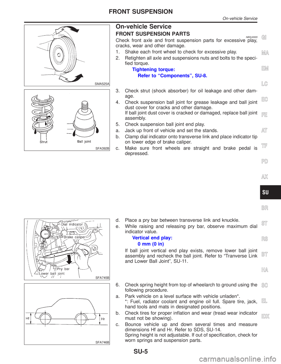
1. Shake each front wheel to check for excessive play.
2. Retighten all axle and suspensions nuts and bolts to the speci-
fied torque.
Tightening torque:
Refer to ªComponentsº, SU-8.
SFA392B
3. Check strut (shock absorber) for oil leakage and other dam-
age.
4. Check suspension ball joint for grease leakage and ball joint
dust cover for cracks and other damage.
If ball joint dust cover is cracked or damaged, replace ball joint
assembly.
5. Check suspension ball joint end play.
a. Jack up front of vehicle and set the stands.
b. Clamp dial indicator onto transverse link and place indicator tip
on lower edge of brake caliper.
c. Make sure front wheels are straight and brake pedal is
depressed.
SFA745B
d. Place a pry bar between transverse link and knuckle.
e. While raising and releasing pry bar, observe maximum dial
indicator value.
Vertical end play:
0mm(0in)
If ball joint vertical end play exists, remove lower ball joint
assembly and recheck the ball joint. Refer to ªTranverse Link
and Lower Ball Jointº, SU-11.
SFA746B
6. Check spring height from top of wheelarch to ground using the
following procedure.
a. Park vehicle on a level surface with vehicle unladen*.
*: Fuel, radiator coolant and engine oil full. Spare tire, jack,
hand tools and mats in designated positions.
b. Check tires for proper inflation and wear (tread wear indicator
must not be showing).
c. Bounce vehicle up and down several times and measure
dimensions Hf and Hr. Refer to SDS, SU-14.
Spring height is not adjustable. If out of specification, check for
worn springs and suspension parts.
GI
MA
EM
LC
EC
FE
AT
TF
PD
AX
BR
ST
RS
BT
HA
SC
EL
IDX
FRONT SUSPENSION
On-vehicle Service
SU-5
Symptom 9. 4WD System Does Not Operate=NBTF0037SYMPTOM: The vehicle cannot be put into 4WD mode.
(Hydraulic system failure)
1 CHECK INPUT SIGNAL
With CONSULT-II
1. Select ªECU INPUT SIGNALSº in Data Monitor.
2. Read out the ON/OFF status of ªCLUTCH PRES SWº.
SMT977D
Without CONSULT-II
Check voltage between transfer control unit harness connector terminal 34 and body ground.
Refer to ªTRANSFER CONTROL UNIT INSPECTION TABLEº, ªTROUBLE DIAGNOSIS Ð GENERAL DESCRIPTIONº,
TF-55.
OK or NG
OK©1. Check transfer fluid level.
2. Disassemble transfer unit and check the following.
ITransfer motor
IMain oil pump assembly
ISub-oil pump assembly
IOil strainer
IControl valve assembly
I2-4WD shift solenoid valve
IOil filter element
ILip seal
IStrainer O-ring
IMain oil pump drive gear
ISeal ring
ID-ring
IClutch piston
IClutch assembly
NG©GO TO 2.
2 CHECK CLUTCH PRESSURE CIRCUIT
Check clutch pressure switch circuit.
Refer to ªDiagnostic Procedureº, ªCLUTCH PRESSURE SWITCHº, TF-80.
OK or NG
OK©GO TO 3.
NG©Check, repair or replace faulty parts.
GI
MA
EM
LC
EC
FE
AT
PD
AX
SU
BR
ST
RS
BT
HA
SC
EL
IDX
TROUBLE DIAGNOSES FOR SYMPTOMS
Symptom 9. 4WD System Does Not Operate
TF-109

