oil level INFINITI QX4 2001 Factory Owner's Guide
[x] Cancel search | Manufacturer: INFINITI, Model Year: 2001, Model line: QX4, Model: INFINITI QX4 2001Pages: 2395, PDF Size: 43.2 MB
Page 2000 of 2395

ItemReference page
Brake pedal and
boosterCheck the pedal for smooth operation and make sure it has the proper dis-
tance under it when depressed fully. Check the brake booster function. Be
sure to keep floor mats away from the pedal.BR-14, ªBrake Pedal and
Bracketº and BR-19,
ªBrake Boosterº
Parking brakeCheck that the lever has the proper travel and make sure that the vehicle is
held securely on a fairly steep hill when only the parking brake is applied.BR-31, ªParking Brake
Controlº
Automatic transmis-
sion ªParkº mecha-
nismCheck that the lock release button on the selector lever operates properly
and smoothly. On a fairly steep hill check that the vehicle is held securely
with the selector lever in the ªPº position without applying any brakes.Ð
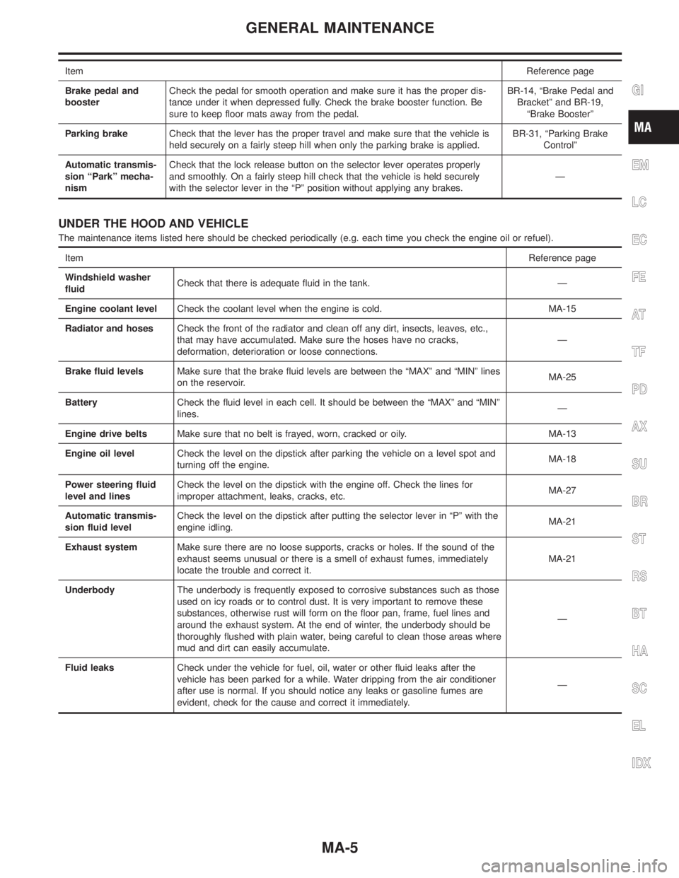
UNDER THE HOOD AND VEHICLE
The maintenance items listed here should be checked periodically (e.g. each time you check the engine oil or refuel).
ItemReference page
Windshield washer
fluidCheck that there is adequate fluid in the tank. Ð
Engine coolant levelCheck the coolant level when the engine is cold. MA-15
Radiator and hosesCheck the front of the radiator and clean off any dirt, insects, leaves, etc.,
that may have accumulated. Make sure the hoses have no cracks,
deformation, deterioration or loose connections.Ð
Brake fluid levelsMake sure that the brake fluid levels are between the ªMAXº and ªMINº lines
on the reservoir.MA-25
BatteryCheck the fluid level in each cell. It should be between the ªMAXº and ªMINº
lines.Ð
Engine drive beltsMake sure that no belt is frayed, worn, cracked or oily. MA-13
Engine oil levelCheck the level on the dipstick after parking the vehicle on a level spot and
turning off the engine.MA-18
Power steering fluid
level and linesCheck the level on the dipstick with the engine off. Check the lines for
improper attachment, leaks, cracks, etc.MA-27
Automatic transmis-
sion fluid levelCheck the level on the dipstick after putting the selector lever in ªPº with the
engine idling.MA-21
Exhaust systemMake sure there are no loose supports, cracks or holes. If the sound of the
exhaust seems unusual or there is a smell of exhaust fumes, immediately
locate the trouble and correct it.MA-21
UnderbodyThe underbody is frequently exposed to corrosive substances such as those
used on icy roads or to control dust. It is very important to remove these
substances, otherwise rust will form on the floor pan, frame, fuel lines and
around the exhaust system. At the end of winter, the underbody should be
thoroughly flushed with plain water, being careful to clean those areas where
mud and dirt can easily accumulate.Ð
Fluid leaksCheck under the vehicle for fuel, oil, water or other fluid leaks after the
vehicle has been parked for a while. Water dripping from the air conditioner
after use is normal. If you should notice any leaks or gasoline fumes are
evident, check for the cause and correct it immediately.Ð
GI
EM
LC
EC
FE
AT
TF
PD
AX
SU
BR
ST
RS
BT
HA
SC
EL
IDX
GENERAL MAINTENANCE
MA-5
Page 2013 of 2395

SMA096D
Changing Engine OilNBMA0015WARNING:
IBe careful not to burn yourself, as the engine oil is hot.
IProlonged and repeated contact with used engine oil may
cause skin cancer; try to avoid direct skin contact with
used oil. If skin contact is made, wash thoroughly with
soap or hand cleaner as soon as possible.
1. Warm up engine, and check for oil leakage from engine com-
ponents.
2. Stop engine and wait for more than 10 minutes.
3. Remove drain plug and oil filler cap.
4. Drain oil and refill with new engine oil.
Oil specification and viscosity
IAPI grade SG or SH, Energy ConservingI&IIorAPIgrade
SJ, Energy Conserving
IAPI Certification Mark
IILSAC grade GF-I & GF-II
ISee ªRECOMMENDED FLUIDS AND LUBRICANTSº, MA-11.
Oil capacity (Approximately):
Unit:(US qt, Imp qt)
Drain and refillWith oil filter change 5.0 (5-1/4, 4-3/8)
Without oil filter change 4.8 (5-1/8, 4-1/4)
Dry engine (engine overhaul) 6.8 (7-1/4, 6)
CAUTION:
IBe sure to clean drain plug and install with new washer.
Oil pan drain plug:
: 29 - 39 N´m (3.0 - 4.0 kg-m, 22 - 29 ft-lb)
IThe refill capacity depends on the oil temperature and
drain time. Use these specifications for reference only.
Always use the dipstick to determine when the proper
amount of oil is in the engine.
JMA122D
5. Warm up engine and check area around drain plug and oil fil-
ter for oil leakage.
6. Stop engine and wait for more than 10 minutes.
7. Check oil level.
SMA097D
Changing Oil FilterNBMA00161. Remove oil filter with Tool.
WARNING:
Be careful not to burn yourself, as the engine and engine oil
are hot.
The filter is a full-flow cartridge type and is provided with a relief
valve.
Refer to LC-7, ªOil Filterº.
ENGINE MAINTENANCE
Changing Engine Oil
MA-18
Page 2017 of 2395

2WD, 4WD model
8.5(9 US qt, 7-1/2 Imp qt)
Drain plug:
: 29 - 39 N´m (3.0 - 4.0 kg-m, 22 - 29 ft-lb)
4. Run engine at idle speed for five minutes.
5. Check fluid level and condition. Refer to MA-21, ªChecking A/T
Fluidº. If fluid is still dirty, repeat steps 2 through 5.
SMA439B
Checking All-mode 4WD Transfer FluidNBMA0022Check for oil leakage and fluid level.
A/T fluid is used for the all-mode 4WD transfer in the factory.
Never start engine while checking fluid level.
Filler plug:
: 10 - 20 N´m (1.0 - 2.0 kg-m, 87 - 174 in-lb)
SMA444B
Changing All-mode 4WD Transfer FluidNBMA0023When changing all-mode 4WD transfer fluid completely, A/T fluid
may be used.
Fluid grade:
Nissan Matic ªDº (Continental U.S. and Alaska) or
Canada NISSAN Automatic Transmission Fluid.
Refer to ªFluids and Lubricantsº, ªRECOMMENDED
FLUIDS AND LUBRICANTSº, MA-11.
Fluid capacity:
3.0(3-1/8 US qt, 2-5/8 Imp qt)
Drain plug:
: 10 - 20 N´m (1.0 - 2.0 kg-m, 87 - 174 in-lb)
CHASSIS AND BODY MAINTENANCE
Changing A/T Fluid (Cont'd)
MA-22
Page 2018 of 2395

SMA231
SMA872C
Checking Propeller ShaftNBMA0024Check propeller shaft for damage, looseness or grease leakage.
Tightening torque: Refer to PD-4, ªComponentsº.
SMA873C
Greasing Propeller ShaftNBMA0025Apply specified grease to nipples provided on propeller shaft.
Grease grade:
Refer to ªRECOMMENDED FLUIDS AND
LUBRICANTSº, MA-11.
SMA440B
Checking Differential Gear OilNBMA0026Check for oil leakage and oil level.
Filler plug:
Front
: 39 - 59 N´m (4 - 6 kg-m, 29 - 43 ft-lb)
Rear
: 59 - 118 N´m (6 - 12 kg-m, 43 - 87 ft-lb)
GI
EM
LC
EC
FE
AT
TF
PD
AX
SU
BR
ST
RS
BT
HA
SC
EL
IDX
CHASSIS AND BODY MAINTENANCE
Checking Propeller Shaft
MA-23
Page 2019 of 2395

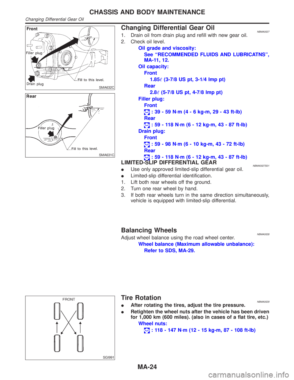
SMA632C
SMA631C
Changing Differential Gear OilNBMA00271. Drain oil from drain plug and refill with new gear oil.
2. Check oil level.
Oil grade and viscosity:
See ªRECOMMENDED FLUIDS AND LUBRICATNSº,
MA-11, 12.
Oil capacity:
Front
1.85(3-7/8 US pt, 3-1/4 Imp pt)
Rear
2.8(5-7/8 US pt, 4-7/8 Imp pt)
Filler plug:
Front
: 39 - 59 N´m (4 - 6 kg-m, 29 - 43 ft-lb)
Rear
: 59 - 118 N´m (6 - 12 kg-m, 43 - 87 ft-lb)
Drain plug:
Front
: 59 - 98 N´m (6 - 10 kg-m, 43 - 72 ft-lb)
Rear
: 59 - 118 N´m (6 - 12 kg-m, 43 - 87 ft-lb)
LIMITED-SLIP DIFFERENTIAL GEARNBMA0027S01IUse only approved limited-slip differential gear oil.
ILimited-slip differential identification.
1. Lift both rear wheels off the ground.
2. Turn one rear wheel by hand.
3. If both rear wheels turn in the same direction simultaneously,
vehicle is equipped with limited-slip differential.
Balancing WheelsNBMA0028Adjust wheel balance using the road wheel center.
Wheel balance (Maximum allowable unbalance):
Refer to SDS, MA-29.
SGI991
Tire RotationNBMA0029IAfter rotating the tires, adjust the tire pressure.
IRetighten the wheel nuts after the vehicle has been driven
for 1,000 km (600 miles). (also in cases of a flat tire, etc.)
Wheel nuts:
: 118 - 147 N´m (12 - 15 kg-m, 87 - 108 ft-lb)
CHASSIS AND BODY MAINTENANCE
Changing Differential Gear Oil
MA-24
Page 2054 of 2395

Pinion Head Height NumberAdd or Remove from the Standard
Pinion Height Washer Thickness
Measurement
þ6 Add 0.06 mm (0.0024 in)
þ5 Add 0.05 mm (0.0020 in)
þ4 Add 0.04 mm (0.0016 in)
þ3 Add 0.03 mm (0.0012 in)
þ2 Add 0.02 mm (0.0008 in)
þ1 Add 0.01 mm (0.0004 in)
0 Use the selected washer thickness
+1 Subtract 0.01 mm (0.0004 in)
+2 Subtract 0.02 mm (0.0008 in)
+3 Subtract 0.03 mm (0.0012 in)
+4 Subtract 0.04 mm (0.0016 in)
+5 Subtract 0.05 mm (0.0020 in)
+6 Subtract 0.06 mm (0.0024 in)
SPD205A
16. Remove the J34309 pinion preload shim selector tool from the
final drive housing and disassemble to retrieve the pinion bear-
ings.
TOOTH CONTACTNBPD0020S03Gear tooth contact pattern check is necessary to verify correct
relationship between ring gear and drive pinion.
Hypoid gear sets which are not positioned properly in relation to
one another may be noisy, or have short life, or both. With a pat-
tern check, the most desirable contact for low noise level and long
life can be assured.
SPD357
1. Thoroughly clean ring gear and drive pinion teeth.
2. Sparingly apply a mixture of powdered ferric oxide and oil or
equivalent to 3 or 4 teeth of ring gear drive side.
GI
MA
EM
LC
EC
FE
AT
TF
AX
SU
BR
ST
RS
BT
HA
SC
EL
IDX
FRONT FINAL DRIVER200A
Adjustment (Cont'd)
PD-29
Page 2081 of 2395

SPD220A
13. Remove the J34309 pinion preload shim selector tool from the
final drive housing and disassemble to retrieve the pinion bear-
ings.
TOOTH CONTACTNBPD0040S02Gear tooth contact pattern check is necessary to verify correct
relationship between ring gear and drive pinion.
Hypoid gear sets which are not positioned properly in relation to
one another may be noisy, or have short life or both. With a pat-
tern check, the most desirable contact for low noise level and long
life can be assured.
SPD005
1. Thoroughly clean ring gear and drive pinion teeth.
2. Sparingly apply a mixture of powdered ferric oxide and oil or
equivalent to 3 or 4 teeth of ring gear drive side.
SPD695
3. Hold companion flange steady by hand and rotate the ring gear
in both directions.
REAR FINAL DRIVEH233B
Adjustment (Cont'd)
PD-56
Page 2182 of 2395

STEERING SYSTEM
SECTION
ST
CONTENTS
PRECAUTIONS...............................................................2
Supplemental Restraint System (SRS)²AIR
BAG²and²SEAT BELT PRE-TENSIONER²...............2
Precautions for Steering System .................................2
PREPARATION...............................................................3
Special Service Tools ..................................................3
Commercial Service Tools ...........................................5
NOISE, VIBRATION AND HARSHNESS (NVH)
TROUBLESHOOTING.....................................................6
NVH Troubleshooting Chart.........................................6
ON-VEHICLE SERVICE..................................................7
Checking Steering Wheel Play ....................................7
Checking Neutral Position on Steering Wheel ............7
PRE-CHECKING........................................................7
CHECKING...............................................................7
Front Wheel Turning Angle ..........................................7
Checking Gear Housing Movement ............................8
Adjusting Rack Retainer ..............................................8
Checking and Adjusting Drive Belts ............................8
Checking Fluid Level ...................................................8
Checking Fluid Leakage ..............................................8
Bleeding Hydraulic System..........................................9
Checking Steering Wheel Turning Force ....................9
Checking Hydraulic System.......................................10
STEERING WHEEL AND STEERING COLUMN......... 11
Components............................................................... 11
Removal and Installation ........................................... 11
STEERING WHEEL................................................. 11
STEERING COLUMN...............................................12
Disassembly and Assembly .......................................13
Inspection...................................................................14
TILT MECHANISM...................................................14
STEERING TRANSFER GEAR.....................................15
Removal .....................................................................15
Installation ..................................................................16
Inspection...................................................................16
POWER STEERING GEAR AND LINKAGE................17
Components...............................................................17
Removal and Installation ...........................................18
Disassembly...............................................................19
Inspection...................................................................20
BOOT.....................................................................20
RACK.....................................................................20
PINION ASSEMBLY.................................................20
GEAR HOUSING CYLINDER....................................20
TIE-ROD OUTER AND INNER SOCKETS..................21
Assembly ...................................................................21
Adjustment .................................................................24
POWER STEERING OIL PUMP....................................27
Components...............................................................27
Pre-disassembly Inspection .......................................27
Disassembly...............................................................28
Inspection...................................................................29
Assembly ...................................................................29
SERVICE DATA AND SPECIFICATIONS (SDS).........32
General Specifications ...............................................32
Steering Wheel ..........................................................32
Steering Column ........................................................32
Steering Transfer Gear ..............................................32
Steering Gear and Linkage .......................................33
Power Steering ..........................................................33
GI
MA
EM
LC
EC
FE
AT
TF
PD
AX
SU
BR
RS
BT
HA
SC
EL
IDX
Page 2189 of 2395

SST601C
Checking Gear Housing MovementNBST00081. Check the movement of steering gear housing during station-
ary steering on a dry paved surface.
IApply a force of 49 N (5 kg, 11 lb) to steering wheel to check
the gear housing movement.
Turn off ignition key while checking.
Movement of gear housing:
±2mm(±0.08 in) or less
2. If movement exceeds the limit, replace mount insulator after
confirming proper installation of gear housing clamps.
SST602C
Adjusting Rack RetainerNBST0009IPerform this driving test on a flat road.
a) Check whether vehicle moves in a straight line when steering
wheel is released.
b) Check whether steering wheel returns to neutral position when
steering wheel is released from a slightly turned (approx. 20É)
position.
IIf any abnormality is found, correct it by resetting adjusting
screw.
Checking and Adjusting Drive BeltsNBST0010Refer to MA-13, ªChecking Drive Beltsº.
SST280BA
Checking Fluid LevelNBST0011Check fluid level.
Use the correct range of the dipstick depending on the fluid tem-
perature. Use the ªHOTº range at 50 to 80ÉC (122 to 176ÉF), or the
ªCOLDº range at 0 to 30ÉC (32 to 86ÉF).
CAUTION:
IDo not overfill.
IRecommended fluid is Genuine Nissan PSF II or equiva-
lent. Refer to MA-11, ªFluids and Lubricantsº.
SST458C
Checking Fluid LeakageNBST0012Check the lines for improper attachment and for leaks, cracks,
damage, loose connections, chafing and deterioration.
1. Run engine between idle speed and 1,000 rpm.
Make sure temperature of fluid in oil tank rises to 60 to 80ÉC
(140 to 176ÉF).
2. Turn steering wheel right-to-left several times.
3. Hold steering wheel at each ªlockº position for five seconds
and carefully check for fluid leakage.
ON-VEHICLE SERVICE
Checking Gear Housing Movement
ST-8
Page 2190 of 2395

CAUTION:
Do not hold the steering wheel in a locked position for more
than 15 seconds.
4. If fluid leakage at connectors is noticed, loosen flare nut and
then retighten.
Do not overtighten connector as this can damage O-ring,
washer and connector.
5. Check rack boots for accumulation of power steering fluid.
Bleeding Hydraulic SystemNBST00131. Raise front end of vehicle until wheels are clear of the ground.
2. Add fluid into oil tank to specified level. Then, quickly turn
steering wheel fully to right and left and lightly touch steering
stoppers.
Repeat steering wheel operation until fluid level no longer
decreases.
3. Start engine.
Repeat step 2 above.
IIncomplete air bleeding will cause the following to occur. When
this happens, bleed air again.
a) Air bubbles in reservoir tank
b) Clicking noise in oil pump
c) Excessive buzzing in oil pump
Fluid noise may occur in the valve or oil pump. This is common
when the vehicle is stationary or while turning steering wheel
slowly. This does not affect performance or durability of the system.
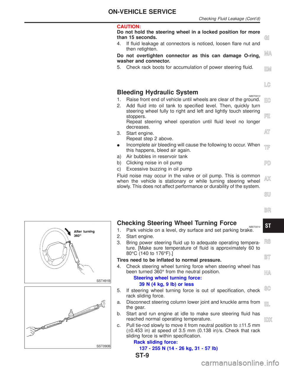
SST491B
SST090B
Checking Steering Wheel Turning ForceNBST00141. Park vehicle on a level, dry surface and set parking brake.
2. Start engine.
3. Bring power steering fluid up to adequate operating tempera-
ture. [Make sure temperature of fluid is approximately 60 to
80ÉC (140 to 176ÉF).]
Tires need to be inflated to normal pressure.
4. Check steering wheel turning force when steering wheel has
been turned 360É from the neutral position.
Steering wheel turning force:
39 N (4 kg, 9 lb) or less
5. If steering wheel turning force is out of specification, check
rack sliding force.
a. Disconnect steering column lower joint and knuckle arms from
the gear.
b. Start and run engine at idle to make sure steering fluid has
reached normal operating temperature.
c. Pull tie-rod slowly to move it from neutral position to±11.5 mm
(±0.453 in) at speed of 3.5 mm (0.138 in)/s. Check that rack
sliding force is within specification.
Rack sliding force:
137 - 255 N (14 - 26 kg, 31 - 57 lb)
GI
MA
EM
LC
EC
FE
AT
TF
PD
AX
SU
BR
RS
BT
HA
SC
EL
IDX
ON-VEHICLE SERVICE
Checking Fluid Leakage (Cont'd)
ST-9