vin INFINITI QX4 2001 Factory Owner's Guide
[x] Cancel search | Manufacturer: INFINITI, Model Year: 2001, Model line: QX4, Model: INFINITI QX4 2001Pages: 2395, PDF Size: 43.2 MB
Page 205 of 2395
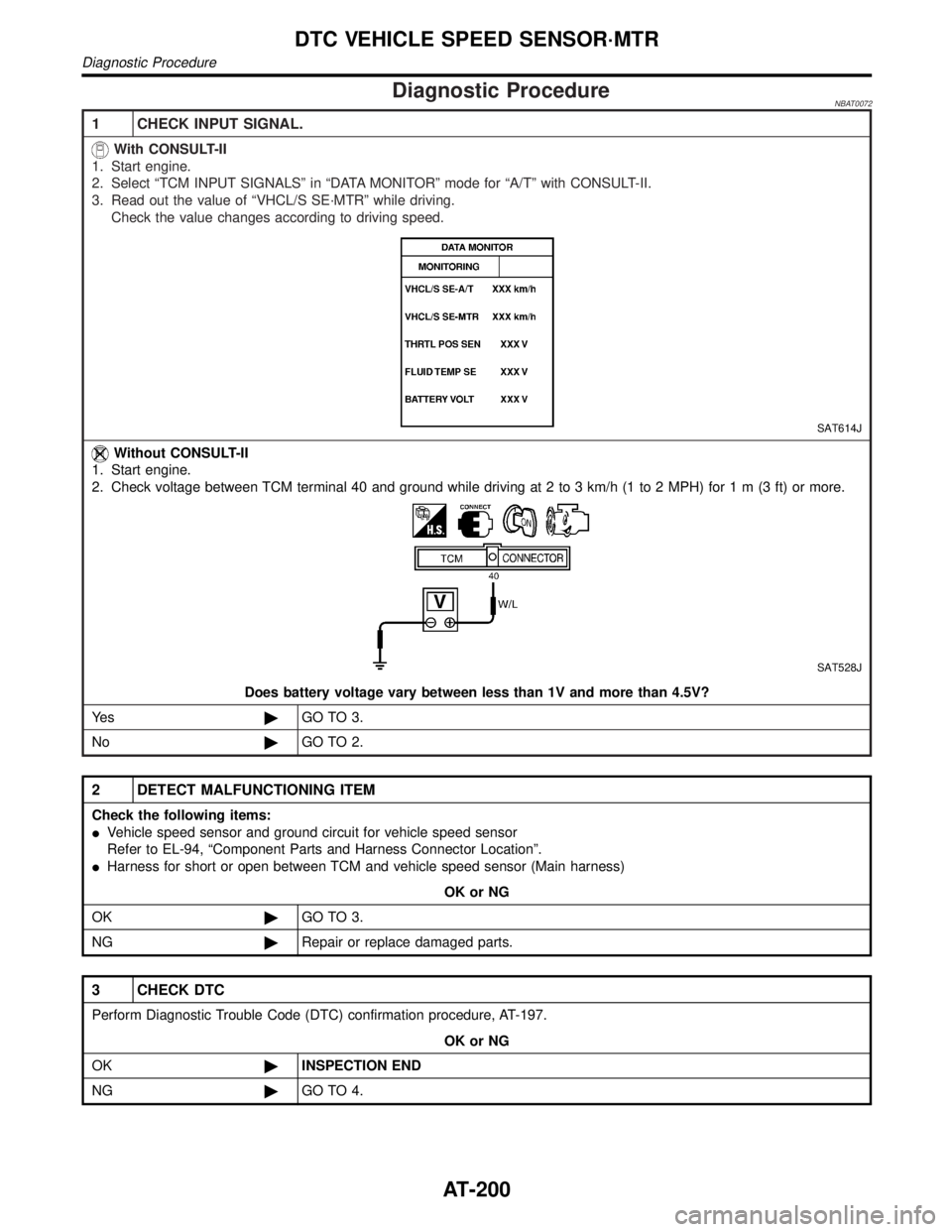
Diagnostic ProcedureNBAT0072
1 CHECK INPUT SIGNAL.
With CONSULT-II
1. Start engine.
2. Select ªTCM INPUT SIGNALSº in ªDATA MONITORº mode for ªA/Tº with CONSULT-II.
3. Read out the value of ªVHCL/S SE´MTRº while driving.
Check the value changes according to driving speed.
SAT614J
Without CONSULT-II
1. Start engine.
2. Check voltage between TCM terminal 40 and ground while driving at 2 to 3 km/h (1 to 2 MPH) for1m(3ft)ormore.
SAT528J
Does battery voltage vary between less than 1V and more than 4.5V?
Ye s©GO TO 3.
No©GO TO 2.
2 DETECT MALFUNCTIONING ITEM
Check the following items:
IVehicle speed sensor and ground circuit for vehicle speed sensor
Refer to EL-94, ªComponent Parts and Harness Connector Locationº.
IHarness for short or open between TCM and vehicle speed sensor (Main harness)
OK or NG
OK©GO TO 3.
NG©Repair or replace damaged parts.
3 CHECK DTC
Perform Diagnostic Trouble Code (DTC) confirmation procedure, AT-197.
OK or NG
OK©INSPECTION END
NG©GO TO 4.
DTC VEHICLE SPEED SENSOR´MTR
Diagnostic Procedure
AT-200
Page 208 of 2395

SAT014K
SAT971J
SAT635I
DIAGNOSTIC TROUBLE CODE (DTC) CONFIRMATION
PROCEDURE
NBAT0224S03CAUTION:
IAlways drive vehicle at a safe speed.
IIf conducting this ªDTC CONFIRMATION PROCEDUREº
again, always turn ignition switch ªOFFº and wait at least
5 seconds before continuing.
After the repair, perform the following procedure to confirm the
malfunction is eliminated.
With CONSULT-II
1) Start engine.
2) Select ªDATA MONITORº mode for ªA/Tº with CONSULT-II.
3) Drive vehicle under the following conditions:
Selector lever in ªDº, vehicle speed higher than 40 km/h (25
MPH), engine speed higher than 1,500 rpm, throttle opening
greater than 1.0/8 of the full throttle position and driving for
more than 5 seconds.
No Tools
1) Start engine.
2) Drive vehicle under the following conditions:
Selector lever in ªDº, vehicle speed higher than 40 km/h (25
MPH), engine speed higher than 1,500 rpm, throttle opening
greater than 1/8 of the full throttle position and driving for more
than 5 seconds.
3) Perform self-diagnosis.
Refer to TCM SELF-DIAGNOSTIC PROCEDURE (No Tools),
AT-46.
GI
MA
EM
LC
EC
FE
TF
PD
AX
SU
BR
ST
RS
BT
HA
SC
EL
IDX
DTC TURBINE REVOLUTION SENSOR
Description (Cont'd)
AT-203
Page 263 of 2395

DIAGNOSTIC PROCEDURE=NBAT0204S03NOTE:
The diagnostic procedure includes inspections for the overdrive
control and throttle position switch circuits.
1 INSPECTION START
Do you have CONSULT-II?
YesorNo
Yes (With CONSULT-II)©GO TO 2.
No (Without CONSULT-
II)©GO TO 3.
2 CHECK PNP SWITCH CIRCUIT (With CONSULT-II)
With CONSULT-II
1. Turn ignition switch to ªONº position.
(Do not start engine.)
2. Select ªTCM INPUT SIGNALSº in ªDATA MONITORº mode for ªA/Tº with CONSULT-II.
3. Read out ªPº, ªRº, ªNº, ªDº, ª2º and ª1º position switches moving selector lever to each position. Check the signal of the
selector lever position is indicated properly.
SAT643J
OK or NG
OK©GO TO 5.
NG©GO TO 4.
TROUBLE DIAGNOSES FOR SYMPTOMS
21. TCM Self-diagnosis Does Not Activate (PNP, Overdrive Control and Throttle Position Switches Circuit Checks) (Cont'd)
AT-258
Page 264 of 2395
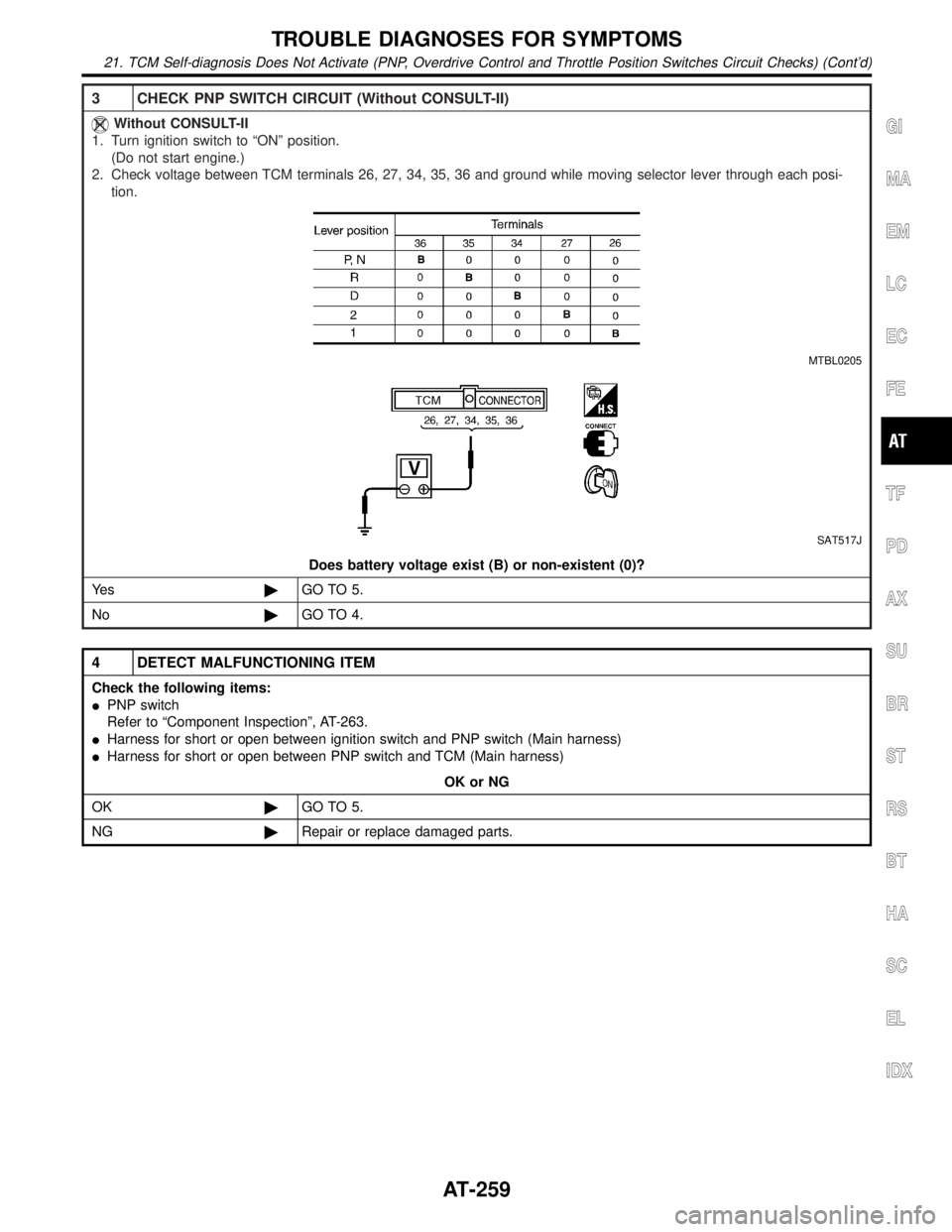
3 CHECK PNP SWITCH CIRCUIT (Without CONSULT-II)
Without CONSULT-II
1. Turn ignition switch to ªONº position.
(Do not start engine.)
2. Check voltage between TCM terminals 26, 27, 34, 35, 36 and ground while moving selector lever through each posi-
tion.
MTBL0205
SAT517J
Does battery voltage exist (B) or non-existent (0)?
Ye s©GO TO 5.
No©GO TO 4.
4 DETECT MALFUNCTIONING ITEM
Check the following items:
IPNP switch
Refer to ªComponent Inspectionº, AT-263.
IHarness for short or open between ignition switch and PNP switch (Main harness)
IHarness for short or open between PNP switch and TCM (Main harness)
OK or NG
OK©GO TO 5.
NG©Repair or replace damaged parts.
GI
MA
EM
LC
EC
FE
TF
PD
AX
SU
BR
ST
RS
BT
HA
SC
EL
IDX
TROUBLE DIAGNOSES FOR SYMPTOMS
21. TCM Self-diagnosis Does Not Activate (PNP, Overdrive Control and Throttle Position Switches Circuit Checks) (Cont'd)
AT-259
Page 268 of 2395
SAT144K
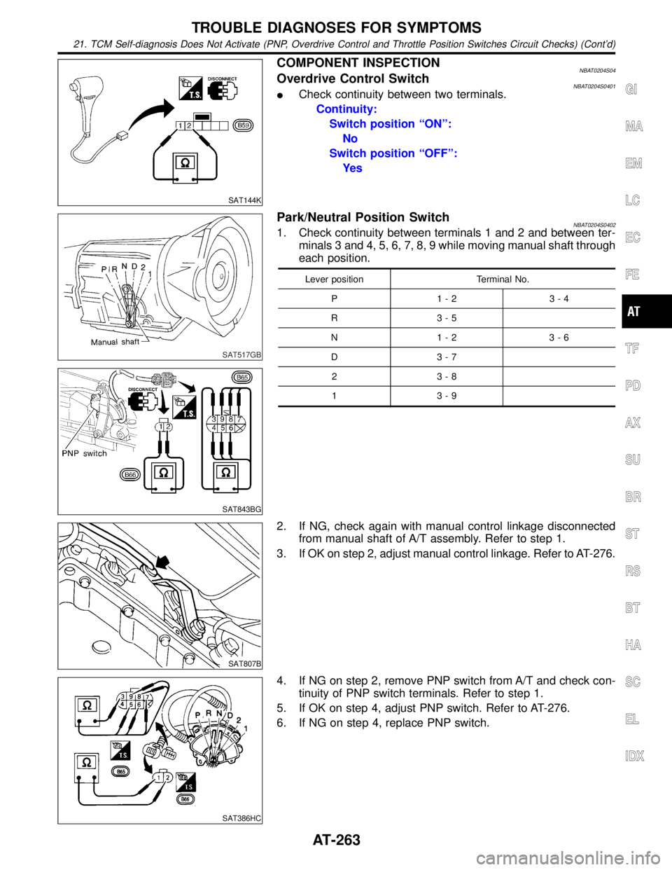
COMPONENT INSPECTIONNBAT0204S04Overdrive Control SwitchNBAT0204S0401ICheck continuity between two terminals.
Continuity:
Switch position ªONº:
No
Switch position ªOFFº:
Ye s
SAT517GB
SAT843BG
Park/Neutral Position SwitchNBAT0204S04021. Check continuity between terminals 1 and 2 and between ter-
minals 3 and 4, 5, 6, 7, 8, 9 while moving manual shaft through
each position.
Lever position Terminal No.
P 1-2 3-4
R 3-5
N 1-2 3-6
D 3-7
2 3-8
1 3-9
SAT807B
2. If NG, check again with manual control linkage disconnected
from manual shaft of A/T assembly. Refer to step 1.
3. If OK on step 2, adjust manual control linkage. Refer to AT-276.
SAT386HC
4. If NG on step 2, remove PNP switch from A/T and check con-
tinuity of PNP switch terminals. Refer to step 1.
5. If OK on step 4, adjust PNP switch. Refer to AT-276.
6. If NG on step 4, replace PNP switch.
GI
MA
EM
LC
EC
FE
TF
PD
AX
SU
BR
ST
RS
BT
HA
SC
EL
IDX
TROUBLE DIAGNOSES FOR SYMPTOMS
21. TCM Self-diagnosis Does Not Activate (PNP, Overdrive Control and Throttle Position Switches Circuit Checks) (Cont'd)
AT-263
Page 278 of 2395

SAT359I
Control Valve Assembly and AccumulatorsNBAT0100REMOVALNBAT0100S011. Remove exhaust front tube.
2. Remove oil pan and gasket and drain ATF.
SAT073BA
3. Remove A/T fluid temperature sensor if necessary.
4. Remove oil strainer.
SAT353B
5. Remove control valve assembly by removing fixing bolts and
disconnecting harness connector.
Bolt length and location
Bolt symbolmm (in)
A 33 (1.30)
B 45 (1.77)
6. Remove solenoids and valves from valve body if necessary.
7. Remove terminal cord assembly if necessary.
SAT074BA
8. Remove accumulatorA, B, CandDby applying compressed
air if necessary.
IHold each piston with rag.
9. Reinstall any part removed.
IAlways use new sealing parts.
GI
MA
EM
LC
EC
FE
TF
PD
AX
SU
BR
ST
RS
BT
HA
SC
EL
IDX
ON-VEHICLE SERVICE
Control Valve Assembly and Accumulators
AT-273
Page 282 of 2395
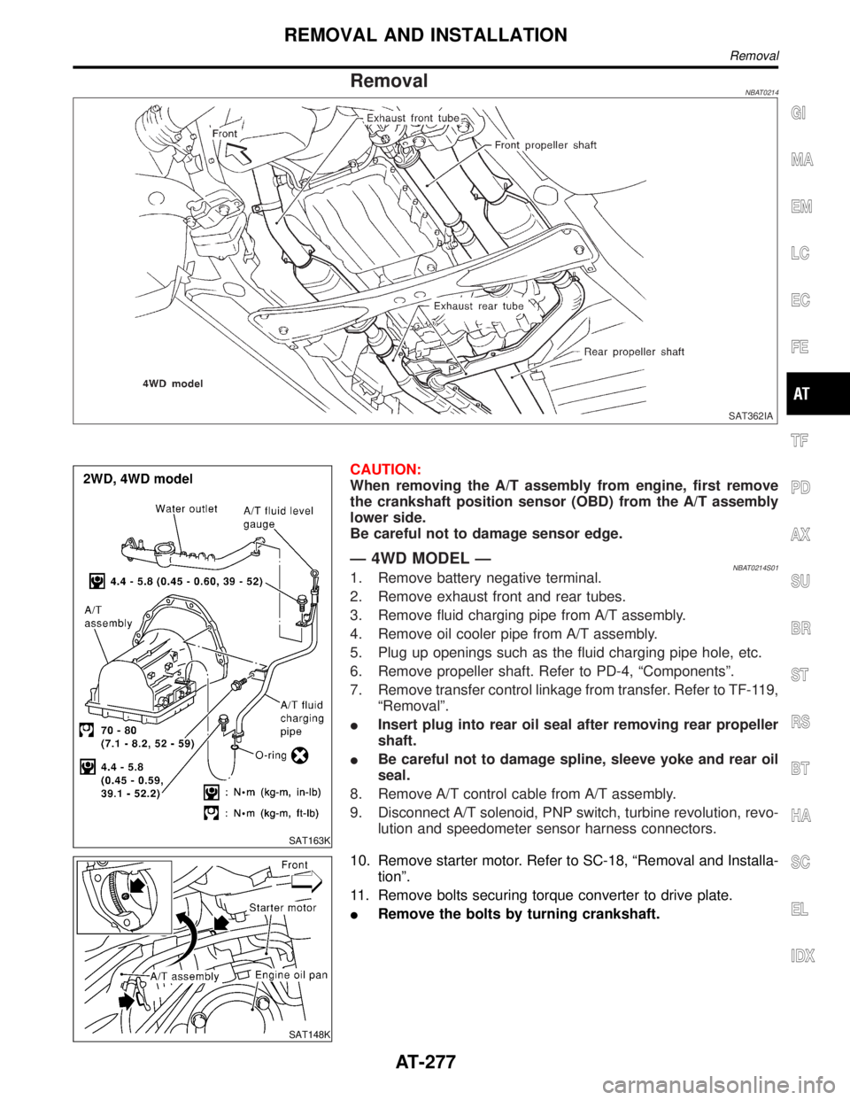
RemovalNBAT0214
SAT362IA
SAT163K
CAUTION:
When removing the A/T assembly from engine, first remove
the crankshaft position sensor (OBD) from the A/T assembly
lower side.
Be careful not to damage sensor edge.
Ð 4WD MODEL ÐNBAT0214S011. Remove battery negative terminal.
2. Remove exhaust front and rear tubes.
3. Remove fluid charging pipe from A/T assembly.
4. Remove oil cooler pipe from A/T assembly.
5. Plug up openings such as the fluid charging pipe hole, etc.
6. Remove propeller shaft. Refer to PD-4, ªComponentsº.
7. Remove transfer control linkage from transfer. Refer to TF-119,
ªRemovalº.
IInsert plug into rear oil seal after removing rear propeller
shaft.
IBe careful not to damage spline, sleeve yoke and rear oil
seal.
8. Remove A/T control cable from A/T assembly.
9. Disconnect A/T solenoid, PNP switch, turbine revolution, revo-
lution and speedometer sensor harness connectors.
SAT148K
10. Remove starter motor. Refer to SC-18, ªRemoval and Installa-
tionº.
11. Remove bolts securing torque converter to drive plate.
IRemove the bolts by turning crankshaft.
GI
MA
EM
LC
EC
FE
TF
PD
AX
SU
BR
ST
RS
BT
HA
SC
EL
IDX
REMOVAL AND INSTALLATION
Removal
AT-277
Page 315 of 2395
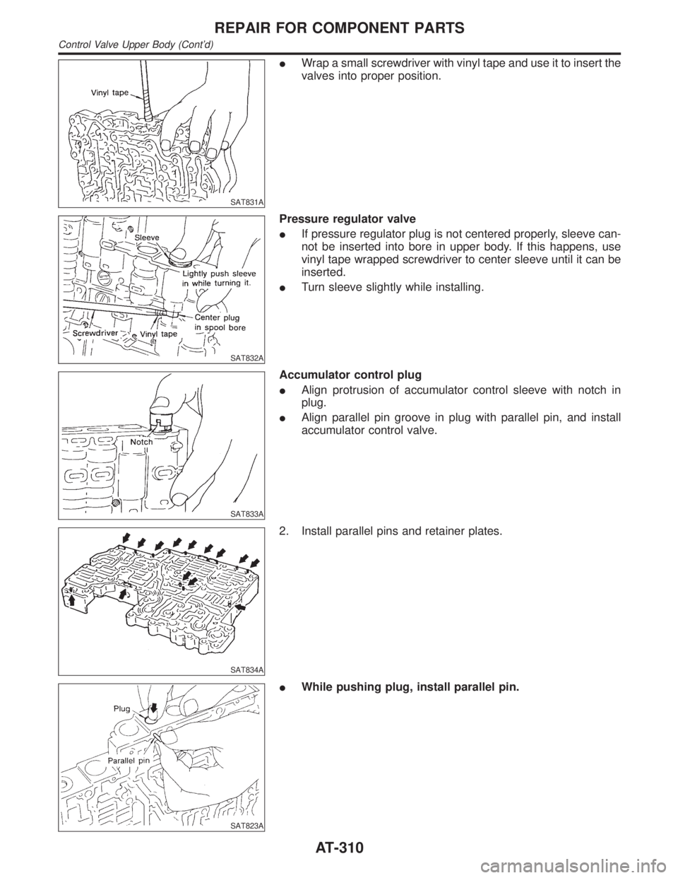
SAT831A
IWrap a small screwdriver with vinyl tape and use it to insert the
valves into proper position.
SAT832A
Pressure regulator valve
IIf pressure regulator plug is not centered properly, sleeve can-
not be inserted into bore in upper body. If this happens, use
vinyl tape wrapped screwdriver to center sleeve until it can be
inserted.
ITurn sleeve slightly while installing.
SAT833A
Accumulator control plug
IAlign protrusion of accumulator control sleeve with notch in
plug.
IAlign parallel pin groove in plug with parallel pin, and install
accumulator control valve.
SAT834A
2. Install parallel pins and retainer plates.
SAT823A
IWhile pushing plug, install parallel pin.
REPAIR FOR COMPONENT PARTS
Control Valve Upper Body (Cont'd)
AT-310
Page 316 of 2395
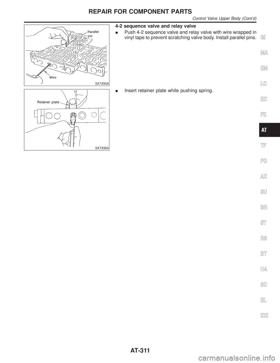
SAT835A
4-2 sequence valve and relay valve
IPush 4-2 sequence valve and relay valve with wire wrapped in
vinyl tape to prevent scratching valve body. Install parallel pins.
SAT836A
IInsert retainer plate while pushing spring.
GI
MA
EM
LC
EC
FE
TF
PD
AX
SU
BR
ST
RS
BT
HA
SC
EL
IDX
REPAIR FOR COMPONENT PARTS
Control Valve Upper Body (Cont'd)
AT-311
Page 369 of 2395
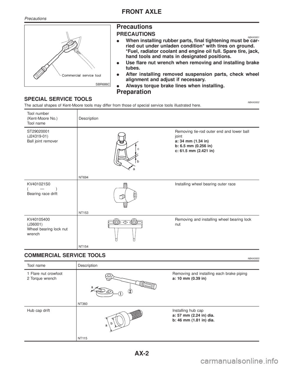
SBR686C
Precautions
PRECAUTIONSNBAX0001IWhen installing rubber parts, final tightening must be car-
ried out under unladen condition* with tires on ground.
*Fuel, radiator coolant and engine oil full. Spare tire, jack,
hand tools and mats in designated positions.
IUse flare nut wrench when removing and installing brake
tubes.
IAfter installing removed suspension parts, check wheel
alignment and adjust if necessary.
IAlways torque brake lines when installing.
Preparation
SPECIAL SERVICE TOOLSNBAX0002The actual shapes of Kent-Moore tools may differ from those of special service tools illustrated here.
Tool number
(Kent-Moore No.)
Tool nameDescription
ST29020001
(J24319-01)
Ball joint remover
NT694
Removing tie-rod outer end and lower ball
joint
a: 34 mm (1.34 in)
b: 6.5 mm (0.256 in)
c: 61.5 mm (2.421 in)
KV401021S0
(Ð)
Bearing race drift
NT153
Installing wheel bearing outer race
KV40105400
(J36001)
Wheel bearing lock nut
wrench
NT154
Removing and installing wheel bearing lock
nut
COMMERCIAL SERVICE TOOLSNBAX0003
Tool name Description
1 Flare nut crowfoot
2 Torque wrench
NT360
Removing and installing each brake piping
a: 10 mm (0.39 in)
Hub cap drift
NT115
Installing hub cap
a: 57 mm (2.24 in) dia.
b: 46 mm (1.81 in) dia.
FRONT AXLE
Precautions
AX-2