vin INFINITI QX4 2001 Factory Manual PDF
[x] Cancel search | Manufacturer: INFINITI, Model Year: 2001, Model line: QX4, Model: INFINITI QX4 2001Pages: 2395, PDF Size: 43.2 MB
Page 523 of 2395

ADJUSTMENTNBBT0018S03
SBT723
If any gap or height difference between glass lid and roof is found,
check glass lid fit and adjust as follows:
Gap AdjustmentNBBT0018S03011. Open shade assembly.
2. Tilt glass lid up then remove side trim.
3. Loosen glass lid securing nuts (3 each on left and right sides),
then tilt glass lid down.
4. Adjust glass lid from outside of vehicle so it resembles ªA-Aº
as shown in the figure above.
5. Tilt glass lid up and down until it is adjusted to ªB-Bº as shown
in the figure above.
6. After adjusting glass lid, tilt glass lid up and tighten nuts.
7. Tilt glass lid up and down several times to check that it moves
smoothly.
Height Difference AdjustmentNBBT0018S03021. Tilt glass lid up and down.
2. Check height difference between roof panel and glass lid to
see if it is as ªA-Aº as shown in the figure above.
3. If necessary, adjust it by using one of following procedures.
IAdjust by adding or removing adjustment shim(s) between
glass lid and link assembly.
IIf glass lid protrudes above roof panel, add shim(s) or plain
washer(s) at sunroof mounting bracket or stud bolt locations to
adjust sunroof installation as required.
SUNROOF
Trouble Diagnoses (Cont'd)
BT-50
Page 526 of 2395

SBF034B
Removal and InstallationNBBT0019
SBT472
SBT473
REMOVALNBBT0019S01After removing moldings, remove glass using piano wire or power
cutting tool and an inflatable pump bag.
WARNING:
When cutting the glass from the vehicle, always wear safety
glasses and heavy gloves to help prevent glass splinters from
entering your eyes or cutting your hands.
CAUTION:
IBe careful not to scratch the glass when removing.
IDo not set or stand the glass on its edge. Small chips may
develop into cracks.
INSTALLATIONNBBT0019S02IUse a genuine Nissan Urethane Adhesive Kit or equivalent
and follow the instructions furnished with it.
IWhile the urethane adhesive is curing, open a door win-
dow. This will prevent the glass from being forced out by
passenger compartment air pressure when a door is
closed.
IThe molding must be installed securely so that it is in
position and leaves no gap.
IInform the customer that the vehicle should remain sta-
tionary until the urethane adhesive has completely cured
(preferably 24 hours). Curing time varies with temperature
and humidity.
WARNING:
IKeep heat and open flames away as primers and adhesive
are flammable.
IThe materials contained in the kit are harmful if
swallowed, and may irritate skin and eyes. Avoid contact
with the skin and eyes.
IUse in an open, well ventilated location. Avoid breathing
the vapors. They can be harmful if inhaled. If affected by
vapor inhalation, immediately move to an area with fresh
air.
IDriving the vehicle before the urethane adhesive has com-
pletely cured may affect the performance of the wind-
shield in case of an accident.
CAUTION:
IDo not use an adhesive which is past its usable term.
Shelf life of this product is limited to six months after the
date of manufacture. Carefully adhere to the expiration or
manufacture date printed on the box.
IKeep primers and adhesive in a cool, dry place. Ideally,
they should be stored in a refrigerator.
IDo not leave primers or adhesive cartridge unattended
with their caps open or off.
IThe vehicle should not be driven for at least 24 hours or
until the urethane adhesive has completely cured. Curing
time varies depending on temperature and humidities. The
curing time will increase under higher temperatures and
lower humidities.
GI
MA
EM
LC
EC
FE
AT
TF
PD
AX
SU
BR
ST
RS
HA
SC
EL
IDX
WINDSHIELD AND WINDOWS
Removal and Installation
BT-53
Page 527 of 2395

WINDSHIELDNBBT0019S03
SBT191-A
Repairing Water Leaks for WindshieldNBBT0019S0301Leaks can be repaired without removing and reinstalling glass.
If water is leaking between the urethane adhesive material and
body or glass, determine the extent of leakage. This can be
done by applying water to the windshield area while pushing
glass outward.
To stop the leak, apply primer (if necessary) and then urethane
adhesive to the leak point.
WINDSHIELD AND WINDOWS
Removal and Installation (Cont'd)
BT-54
Page 554 of 2395

Tool name
(Kent-Moore No.)Description
Socket wrench
NT705
Removing and installing engine coolant tempera-
ture sensor
Oxygen sensor thread
cleaner
(J-43897-18)
(J-43897-12)
NT828
Reconditioning the exhaust system threads before
installing a new oxygen sensor. Use with anti-seize
lubricant shown below.
a: J-43897-18 18 mm diameter with pitch 1.5
mm, for Zirconia Oxygen Sensor
b: J-43897-12 12 mm diameter with pitch 1.25
mm, for Titania Oxygen Sensor
Anti-seize lubricant
(Permatex
TM133AR or
equivalent meeting MIL
specification MIL-A-907)
NT779
Lubricating oxygen sensor thread cleaning tool
when reconditioning exhaust system threads.
GI
MA
EM
LC
FE
AT
TF
PD
AX
SU
BR
ST
RS
BT
HA
SC
EL
IDX
PREPARATION
Commercial Service Tools (Cont'd)
EC-19
Page 566 of 2395

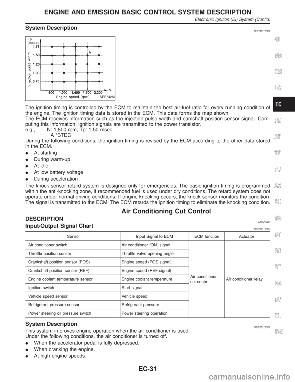
System DescriptionNBEC0015S02
SEF742M
The ignition timing is controlled by the ECM to maintain the best air-fuel ratio for every running condition of
the engine. The ignition timing data is stored in the ECM. This data forms the map shown.
The ECM receives information such as the injection pulse width and camshaft position sensor signal. Com-
puting this information, ignition signals are transmitted to the power transistor.
e.g., N: 1,800 rpm, Tp: 1.50 msec
A ÉBTDC
During the following conditions, the ignition timing is revised by the ECM according to the other data stored
in the ECM.
IAt starting
IDuring warm-up
IAt idle
IAt low battery voltage
IDuring acceleration
The knock sensor retard system is designed only for emergencies. The basic ignition timing is programmed
within the anti-knocking zone, if recommended fuel is used under dry conditions. The retard system does not
operate under normal driving conditions. If engine knocking occurs, the knock sensor monitors the condition.
The signal is transmitted to the ECM. The ECM retards the ignition timing to eliminate the knocking condition.
Air Conditioning Cut Control
DESCRIPTIONNBEC0016Input/Output Signal ChartNBEC0016S01
Sensor Input Signal to ECM ECM function Actuator
Air conditioner switch Air conditioner ªONº signal
Air conditioner
cut controlAir conditioner relay Throttle position sensor Throttle valve opening angle
Crankshaft position sensor (POS) Engine speed (POS signal)
Crankshaft position sensor (REF) Engine speed (REF signal)
Engine coolant temperature sensor Engine coolant temperature
Ignition switch Start signal
Vehicle speed sensor Vehicle speed
Refrigerant pressure sensor Refrigerant pressure
Power steering oil pressure switch Power steering operation
System DescriptionNBEC0016S02This system improves engine operation when the air conditioner is used.
Under the following conditions, the air conditioner is turned off.
IWhen the accelerator pedal is fully depressed.
IWhen cranking the engine.
IAt high engine speeds.
GI
MA
EM
LC
FE
AT
TF
PD
AX
SU
BR
ST
RS
BT
HA
SC
EL
IDX
ENGINE AND EMISSION BASIC CONTROL SYSTEM DESCRIPTION
Electronic Ignition (EI) System (Cont'd)
EC-31
Page 594 of 2395

IntroductionNBEC0029The ECM has an on board diagnostic system, which detects malfunctions related to engine sensors or actua-
tors. The ECM also records various emission-related diagnostic information including:
Emission-related diagnostic information SAE Mode
Diagnostic Trouble Code (DTC) Mode 3 of SAE J1979
Freeze Frame data Mode 2 of SAE J1979
System Readiness Test (SRT) code Mode 1 of SAE J1979
1st Trip Diagnostic Trouble Code (1st Trip DTC) Mode 7 of SAE J1979
1st Trip Freeze Frame data
Test values and Test limits Mode 6 of SAE J1979
The above information can be checked using procedures listed in the table below.
X: Applicable Ð: Not applicable
DTC 1st trip DTCFreeze Frame
data1st trip Freeze
Frame dataSRT code Test value
CONSULT-II X X X X X Ð
GST X X*1 X Ð X X
*1: 1st trip DTCs for self-diagnoses concerning SRT items cannot be shown on the GST display.
The malfunction indicator lamp (MIL) on the instrument panel lights up when the same malfunction is detected
in two consecutive trips (Two trip detection logic), or when the ECM enters fail-safe mode. (Refer to EC-117.)
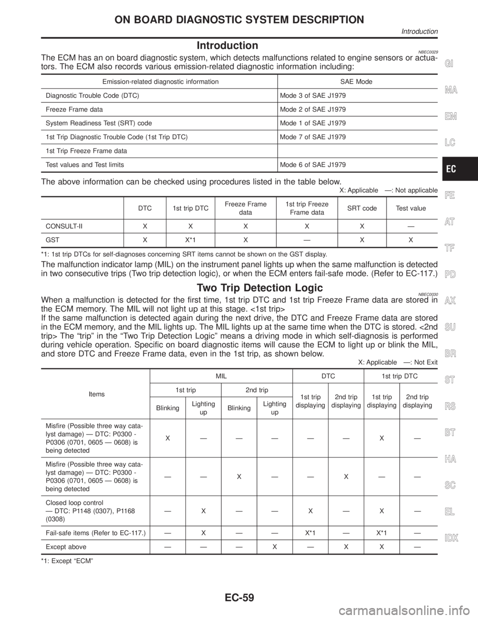
Two Trip Detection LogicNBEC0030When a malfunction is detected for the first time, 1st trip DTC and 1st trip Freeze Frame data are stored in
the ECM memory. The MIL will not light up at this stage. <1st trip>
If the same malfunction is detected again during the next drive, the DTC and Freeze Frame data are stored
in the ECM memory, and the MIL lights up. The MIL lights up at the same time when the DTC is stored. <2nd
trip> The ªtripº in the ªTwo Trip Detection Logicº means a driving mode in which self-diagnosis is performed
during vehicle operation. Specific on board diagnostic items will cause the ECM to light up or blink the MIL,
and store DTC and Freeze Frame data, even in the 1st trip, as shown below.
X: Applicable Ð: Not Exit
ItemsMIL DTC 1st trip DTC
1st trip 2nd trip
1st trip
displaying2nd trip
displaying1st trip
displaying2nd trip
displaying
BlinkingLighting
upBlinkingLighting
up
Misfire (Possible three way cata-
lyst damage) Ð DTC: P0300 -
P0306 (0701, 0605 Ð 0608) is
being detectedX ÐÐÐÐÐ X Ð
Misfire (Possible three way cata-
lyst damage) Ð DTC: P0300 -
P0306 (0701, 0605 Ð 0608) is
being detectedÐÐ X ÐÐ X ÐÐ
Closed loop control
Ð DTC: P1148 (0307), P1168
(0308)ÐXÐÐXÐXÐ
Fail-safe items (Refer to EC-117.) Ð X Ð Ð X*1 Ð X*1 Ð
Except above Ð Ð Ð X Ð X X Ð
*1: Except ªECMº
GI
MA
EM
LC
FE
AT
TF
PD
AX
SU
BR
ST
RS
BT
HA
SC
EL
IDX
ON BOARD DIAGNOSTIC SYSTEM DESCRIPTION
Introduction
EC-59
Page 595 of 2395

Emission-related Diagnostic InformationNBEC0031DTC AND 1ST TRIP DTCNBEC0031S01The 1st trip DTC (whose number is the same as the DTC number) is displayed for the latest self-diagnostic
result obtained. If the ECM memory was cleared previously, and the 1st trip DTC did not reoccur, the 1st trip
DTC will not be displayed.
If a malfunction is detected during the 1st trip, the 1st trip DTC is stored in the ECM memory. The MIL will not
light up (two trip detection logic). If the same malfunction is not detected in the 2nd trip (meeting the required
driving pattern), the 1st trip DTC is cleared from the ECM memory. If the same malfunction is detected in the
2nd trip, both the 1st trip DTC and DTC are stored in the ECM memory and the MIL lights up. In other words,
the DTC is stored in the ECM memory and the MIL lights up when the same malfunction occurs in two con-
secutive trips. If a 1st trip DTC is stored and a non-diagnostic operation is performed between the 1st and
2nd trips, only the 1st trip DTC will continue to be stored. For malfunctions that blink or light up the MIL dur-
ing the 1st trip, the DTC and 1st trip DTC are stored in the ECM memory.
Procedures for clearing the DTC and the 1st trip DTC from the ECM memory are described in ªHOW TO
ERASE EMISSION-RELATED DIAGNOSTIC INFORMATIONº, EC-72.
For malfunctions in which 1st trip DTCs are displayed, refer to EC-69. These items are required by legal
regulations to continuously monitor the system/component. In addition, the items monitored non-continuously
are also displayed on CONSULT-II.
1st trip DTC is specified in Mode 7 of SAE J1979. 1st trip DTC detection occurs without lighting up the MIL
and therefore does not warn the driver of a problem. However, 1st trip DTC detection will not prevent the
vehicle from being tested, for example during Inspection/Maintenance (I/M) tests.
When a 1st trip DTC is detected, check, print out or write down and erase (1st trip) DTC and Freeze Frame
data as specified in ªWork Flowº procedure Step II, refer to EC-99. Then perform ªDTC Confirmation Proce-
dureº or ªOverall Function Checkº to try to duplicate the problem. If the malfunction is duplicated, the item
requires repair.
How to Read DTC and 1st Trip DTCNBEC0031S0101DTC and 1st trip DTC can be read by the following methods.
With CONSULT-II
With GST
CONSULT-II or GST (Generic Scan Tool) Examples: P0340, P1320, P0705, P0750, etc.
These DTCs are prescribed by SAE J2012.
(CONSULT-II also displays the malfunctioning component or system.)
I1st trip DTC No. is the same as DTC No.
IOutput of a DTC indicates a malfunction. However, GST does not indicate whether the malfunction
is still occurring or has occurred in the past and has returned to normal. CONSULT-II can identify
malfunction status as shown below. Therefore, using CONSULT-II (if available) is recommended.
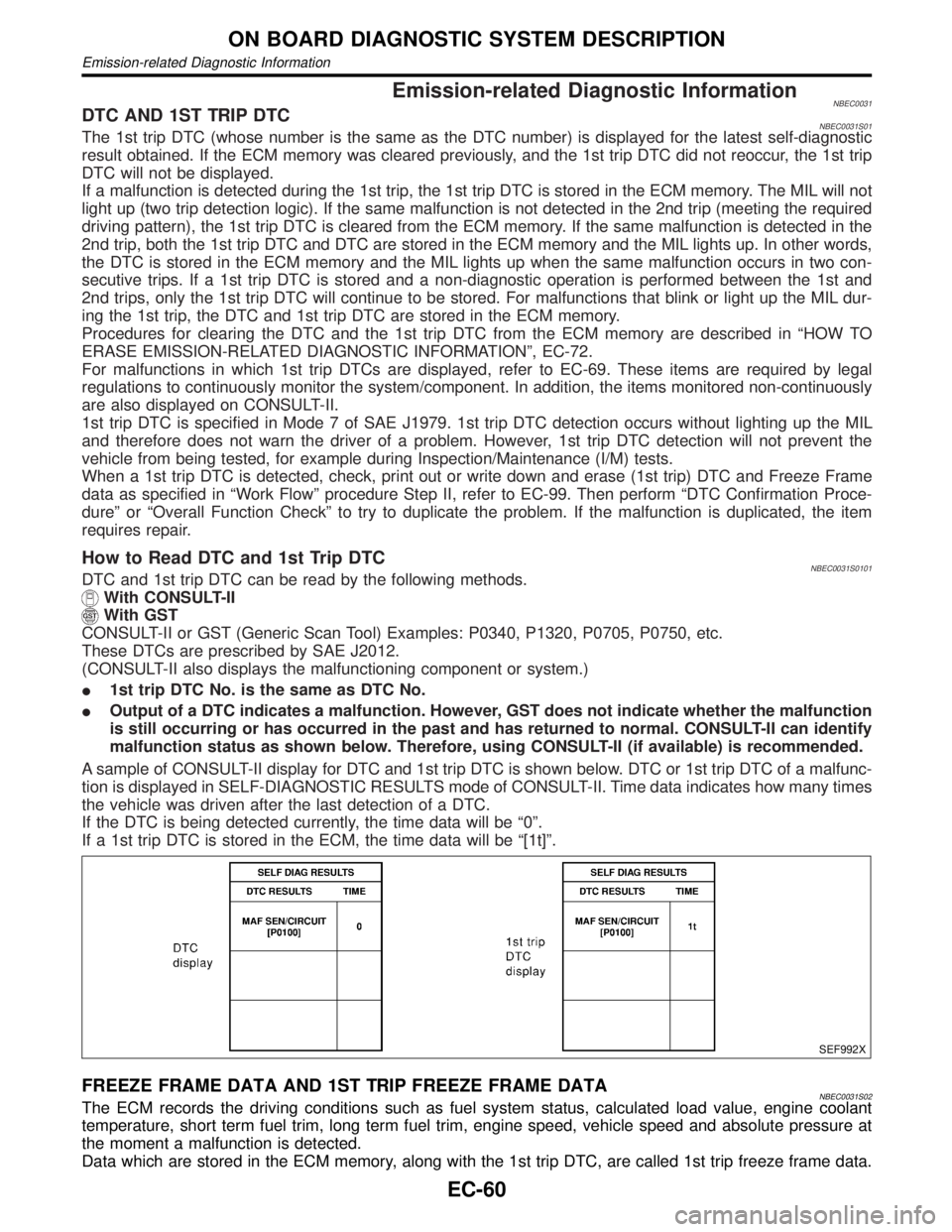
A sample of CONSULT-II display for DTC and 1st trip DTC is shown below. DTC or 1st trip DTC of a malfunc-
tion is displayed in SELF-DIAGNOSTIC RESULTS mode of CONSULT-II. Time data indicates how many times
the vehicle was driven after the last detection of a DTC.
If the DTC is being detected currently, the time data will be ª0º.
If a 1st trip DTC is stored in the ECM, the time data will be ª[1t]º.
SEF992X
FREEZE FRAME DATA AND 1ST TRIP FREEZE FRAME DATANBEC0031S02The ECM records the driving conditions such as fuel system status, calculated load value, engine coolant
temperature, short term fuel trim, long term fuel trim, engine speed, vehicle speed and absolute pressure at
the moment a malfunction is detected.
Data which are stored in the ECM memory, along with the 1st trip DTC, are called 1st trip freeze frame data.
ON BOARD DIAGNOSTIC SYSTEM DESCRIPTION
Emission-related Diagnostic Information
EC-60
Page 596 of 2395

The data, stored together with the DTC data, are called freeze frame data and displayed on CONSULT-II or
GST. The 1st trip freeze frame data can only be displayed on the CONSULT-II screen, not on the GST. For
details, see EC-85.
Only one set of freeze frame data (either 1st trip freeze frame data or freeze frame data) can be stored in the
ECM. 1st trip freeze frame data is stored in the ECM memory along with the 1st trip DTC. There is no prior-
ity for 1st trip freeze frame data and it is updated each time a different 1st trip DTC is detected. However, once
freeze frame data (2nd trip detection/MIL on) is stored in the ECM memory, 1st trip freeze frame data is no
longer stored. Remember, only one set of freeze frame data can be stored in the ECM. The ECM has the fol-
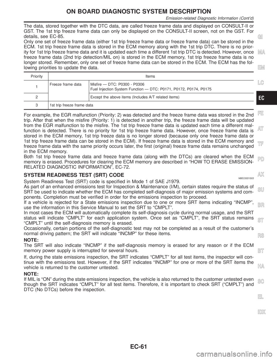
lowing priorities to update the data.
Priority Items
1Freeze frame data Misfire Ð DTC: P0300 - P0306
Fuel Injection System Function Ð DTC: P0171, P0172, P0174, P0175
2 Except the above items (Includes A/T related items)
3 1st trip freeze frame data
For example, the EGR malfunction (Priority: 2) was detected and the freeze frame data was stored in the 2nd
trip. After that when the misfire (Priority: 1) is detected in another trip, the freeze frame data will be updated
from the EGR malfunction to the misfire. The 1st trip freeze frame data is updated each time a different mal-
function is detected. There is no priority for 1st trip freeze frame data. However, once freeze frame data is
stored in the ECM memory, 1st trip freeze data is no longer stored (because only one freeze frame data or
1st trip freeze frame data can be stored in the ECM). If freeze frame data is stored in the ECM memory and
freeze frame data with the same priority occurs later, the first (original) freeze frame data remains unchanged
in the ECM memory.
Both 1st trip freeze frame data and freeze frame data (along with the DTCs) are cleared when the ECM
memory is erased. Procedures for clearing the ECM memory are described in ªHOW TO ERASE EMISSION-
RELATED DIAGNOSTIC INFORMATIONº, EC-72.
SYSTEM READINESS TEST (SRT) CODENBEC0031S03System Readiness Test (SRT) code is specified in Mode 1 of SAE J1979.
As part of an enhanced emissions test for Inspection & Maintenance (I/M), certain states require the status of
SRT be used to indicate whether the ECM has completed self-diagnosis of major emission systems and com-
ponents. Completion must be verified in order for the emissions inspection to proceed.
If a vehicle is rejected for a State emissions inspection due to one or more SRT items indicating ªINCMPº,
use the information in this Service Manual to set the SRT to ªCMPLTº.
In most cases the ECM will automatically complete its self-diagnosis cycle during normal usage, and the SRT
status will indicate ªCMPLTº for each application system. Once set as ªCMPLTº, the SRT status remains
ªCMPLTº until the self-diagnosis memory is erased.
Occasionally, certain portions of the self-diagnostic test may not be completed as a result of the customer's
normal driving pattern; the SRT will indicate ªINCMPº for these items.
NOTE:
The SRT will also indicate ªINCMPº if the self-diagnosis memory is erased for any reason or if the ECM
memory power supply is interrupted for several hours.
If, during the state emissions inspection, the SRT indicates ªCMPLTº for all test items, the inspector will con-
tinue with the emissions test. However, if the SRT indicates ªINCMPº for one or more of the SRT items the
vehicle is returned to the customer untested.
NOTE:
If MIL is ªONº during the state emissions inspection, the vehicle is also returned to the customer untested even
though the SRT indicates ªCMPLTº for all test items. Therefore, it is important to check SRT (ªCMPLTº) and
DTC (No DTCs) before the inspection.
GI
MA
EM
LC
FE
AT
TF
PD
AX
SU
BR
ST
RS
BT
HA
SC
EL
IDX
ON BOARD DIAGNOSTIC SYSTEM DESCRIPTION
Emission-related Diagnostic Information (Cont'd)
EC-61
Page 597 of 2395

SRT Item=NBEC0031S0310The table below shows required self-diagnostic items to set the SRT to ªCMPLTº.
SRT item
(CONSULT-II indica-
tion)Perfor-
mance Pri-
ority*Required self-diagnostic items to set the SRT to ªCMPLTºCorresponding
DTC No.
CATALYST 3 Three way catalyst function P0420, P0430
EVAP SYSTEM 2 EVAP control system (small leak) (negative pressure) P0440
3 EVAP control system (very small leak) (negative pressure)/
(positive pressure)P1441
3 EVAP control system purge flow monitoring P1447
O2 SENSOR 3 Heated oxygen sensor 1 (front) (circuit) P0130, P0150
Heated oxygen sensor 1 (front) (lean shift monitoring) P0131, P0151
Heated oxygen sensor 1 (front) (rich shift monitoring) P0132, P0152
Heated oxygen sensor 1 (front) (response monitoring) P0133, P0153
Heated oxygen sensor 1 (front) (high voltage) P0134, P0154
Heated oxygen sensor 2 (rear) (min. voltage monitoring) P0137, P0157
Heated oxygen sensor 2 (rear) (max. voltage monitoring) P0138, P0158
Heated oxygen sensor 2 (rear) (response monitoring) P0139, P0159
Heated oxygen sensor 2 (rear) (high voltage) P0140, P0160
O2 SEN HEATER 3 Heated oxygen sensor 1 heater (front) P0135, P0155
Heated oxygen sensor 2 heater (rear) P0141, P0161
*: If completion of several SRTs is required, perform driving patterns (DTC confirmation procedure), one by one based on the priority
for models with CONSULT-II.
ON BOARD DIAGNOSTIC SYSTEM DESCRIPTION
Emission-related Diagnostic Information (Cont'd)
EC-62
Page 598 of 2395

SRT Set Timing=NBEC0031S0311SRT is set as ªCMPLTº after self-diagnosis has been performed one or more times. Completion of SRT is done
regardless of whether the result is OK or NG. The set timing is different between OK and NG results and is
shown in the table below.
Self-diagnosis resultExample
DiagnosisIgnition cycle
+ON,OFF+ON,OFF+ON,OFF+ON,
All OK Case 1 P0400 OK (1) Ð (1) OK (2) Ð (2)
P0402 OK (1) Ð (1) Ð (1) OK (2)
P1402 OK (1) OK (2) Ð (2) Ð (2)
SRT of EGR ªCMPLTº ªCMPLTº ªCMPLTº ªCMPLTº
Case 2 P0400 OK (1) Ð (1) Ð (1) Ð (1)
P0402 Ð (0) Ð (0) OK (1) Ð (1)
P1402 OK (1) OK (2) Ð (2) Ð (2)
SRT of EGR ªINCMPº ªINCMPº ªCMPLTº ªCMPLTº
NG exists Case 3 P0400 OK OK Ð Ð
P0402 Ð Ð Ð Ð
P1402 NG Ð NGNG
(Consecutive NG)
(1st trip)
DTC1st trip DTC Ð 1st trip DTCDTC
(= MIL ªONº)
SRT of EGR ªINCMPº ªINCMPº ªINCMPº ªCMPLTº
OK: Self-diagnosis is carried out and the result is OK.
NG: Self-diagnosis is carried out and the result is NG.
Ð: Self-diagnosis is not carried out.
When all SRT related self-diagnoses showed OK results in a single cycle (Ignition OFF-ON-OFF), the SRT
will indicate ªCMPLTº.,Case 1 above
When all SRT related self-diagnoses showed OK results through several different cycles, the SRT will indi-
cate ªCMPLTº at the time the respective self-diagnoses have at least one OK result.,Case 2 above
If one or more SRT related self-diagnoses showed NG results in 2 consecutive cycles, the SRT will also indi-
cate ªCMPLTº.,Case 3 above
The table above shows that the minimum number of cycles for setting SRT as ªINCMPº is one (1) for each
self-diagnosis (Case1&2)ortwo(2)foroneofself-diagnoses (Case 3). However, in preparation for the state
emissions inspection, it is unnecessary of each self-diagnosis to be executed twice (Case 3) for the following
reasons:
IThe SRT will indicate ªCMPLTº at the time the respective self-diagnoses have one (1) OK result.
IThe emissions inspection requires ªCMPLTº of the SRT only with OK self-diagnosis results.
IWhen, during SRT driving pattern, 1st trip DTC (NG) is detected prior to ªCMPLTº of SRT, the self-diag-
nosis memory must be erased from ECM after repair.
IIf the 1st trip DTC is erased, all the SRT will indicate ªINCMPº.
NOTE:
SRT can be set as ªCMPLTº together with the DTC(s). Therefore, DTC check must always be carried out prior
to the state emission inspection even though the SRT indicates ªCMPLTº.
SRT Service ProcedureNBEC0031S0312If a vehicle has failed the state emissions inspection due to one or more SRT items indicating ªINCMPº, review
the flowchart diagnostic sequence on the next page.
GI
MA
EM
LC
FE
AT
TF
PD
AX
SU
BR
ST
RS
BT
HA
SC
EL
IDX
ON BOARD DIAGNOSTIC SYSTEM DESCRIPTION
Emission-related Diagnostic Information (Cont'd)
EC-63