vin INFINITI QX4 2001 Factory User Guide
[x] Cancel search | Manufacturer: INFINITI, Model Year: 2001, Model line: QX4, Model: INFINITI QX4 2001Pages: 2395, PDF Size: 43.2 MB
Page 48 of 2395

SAT014K
5. Touch ªA/Tº.
SAT971J
6. Touch ªDTC WORK SUPPORTº.
SAT018K
7. Touch select item menu (1ST, 2ND, etc.).
SAT589J
8. Touch ªSTARTº.
SAT019K
9. Perform driving test according to ªDTC CONFIRMATION PRO-
CEDUREº in ªTROUBLE DIAGNOSIS FOR DTCº.
GI
MA
EM
LC
EC
FE
TF
PD
AX
SU
BR
ST
RS
BT
HA
SC
EL
IDX
ON BOARD DIAGNOSTIC SYSTEM DESCRIPTION
CONSULT-II (Cont'd)
AT-43
Page 59 of 2395

DIAGNOSTIC WORKSHEET=NBAT0019S01Information From CustomerNBAT0019S0101KEY POINTS
WHAT..... Vehicle & A/T model
WHEN..... Date, Frequencies
WHERE..... Road conditions
HOW..... Operating conditions, Symptoms
Customer name MR/MS Model & Year VIN
Trans. model Engine Mileage
Incident Date Manuf. Date In Service Date
FrequencylContinuouslIntermittent ( times a day)
SymptomslVehicle does not move. (lAny positionlParticular position)
lNo up-shift (l1st,2ndl2nd,3rdl3rd,O/D)
lNo down-shift (lO/D,3rdl3rd,2ndl2nd,1st)
lLockup malfunction
lShift point too high or too low.
lShift shock or slip (lN,DlLockuplAny drive position)
lNoise or vibration
lNo kickdown
lNo pattern select
lOthers
()
O/D OFF indicator lamp Blinks for about 8 seconds.
lContinuously litlNot lit
Malfunction indicator lamp (MIL)lContinuously litlNot lit
TROUBLE DIAGNOSIS Ð INTRODUCTION
Introduction (Cont'd)
AT-54
Page 82 of 2395

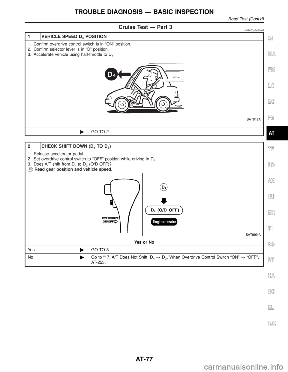
Cruise Test Ð Part 3=NBAT0024S0406
1 VEHICLE SPEED D4POSITION
1. Confirm overdrive control switch is in ªONº position.
2. Confirm selector lever is in ªDº position.
3. Accelerate vehicle using half-throttle to D
4.
SAT812A
©GO TO 2.
2 CHECK SHIFT DOWN (D4TO D3)
1. Release accelerator pedal.
2. Set overdrive control switch to ªOFFº position while driving in D
4.
3. Does A/T shift from D
4to D3(O/D OFF)?
Read gear position and vehicle speed.
SAT999IA
YesorNo
Ye s©GO TO 3.
No©Go to ª17. A/T Does Not Shift: D
4,D3, When Overdrive Control Switch ªONº,ªOFFº,
AT-253.
GI
MA
EM
LC
EC
FE
TF
PD
AX
SU
BR
ST
RS
BT
HA
SC
EL
IDX
TROUBLE DIAGNOSIS Ð BASIC INSPECTION
Road Test (Cont'd)
AT-77
Page 83 of 2395

3 CHECK ENGINE BRAKE
Does vehicle decelerate by engine brake?
SAT999IA
YesorNo
Ye s©GO TO 4.
No©Go to ª15. Engine Speed Does Not Return To Idle (Light Braking D
4,D3)º, AT-250.
4 CHECK SHIFT DOWN (D3TO D2)
1. Move selector lever from ªDº to ª2º position while driving in D3(O/D OFF).
2. Does A/T shift from D
3(O/D OFF) to 22?
Read gear position.
SAT791GB
YesorNo
Ye s©GO TO 5.
No©Go to ª18. A/T Does Not Shift: D
3,D2, When Selector Lever ªDº,ª2º Positionº,
AT-254.
TROUBLE DIAGNOSIS Ð BASIC INSPECTION
Road Test (Cont'd)
AT-78
Page 84 of 2395

5 CHECK ENGINE BRAKE
Does vehicle decelerate by engine brake?
SAT791GB
YesorNo
Ye s©GO TO 6.
No©Go to ª15. Engine Speed Does Not Return To Idle (Light Braking D
4,D3)º, AT-250.
6 CHECK SHIFT DOWN (22TO 11)
1. Move selector lever from ª2º to ª1º position while driving in 22.
2. Does A/T shift from 2
2to 11position?
SAT778B
YesorNo
Ye s©GO TO 7.
No©Go to ª19. A/T Does Not Shift: 2
2,11, When Selector lever ª2º,ª1º Positionº, AT-255.
GI
MA
EM
LC
EC
FE
TF
PD
AX
SU
BR
ST
RS
BT
HA
SC
EL
IDX
TROUBLE DIAGNOSIS Ð BASIC INSPECTION
Road Test (Cont'd)
AT-79
Page 98 of 2395

Terminal
No.Wire color Item ConditionJudgement
standard
(Approx.)
11 L/WShift solenoid
valve A
When shift solenoid valve A operates.
(When driving in ªD
1ºorªD4º.)Battery volt-
age
When shift solenoid valve A does not operate.
(When driving in ªD
2ºorªD3º.)0V
12 L/RShift solenoid
valve BWhen shift solenoid valve B operates.
(When driving in ªD
1ºorªD2º.)Battery volt-
age
When shift solenoid valve B does not operate.
(When driving in ªD
3ºorªD4º.)0V
13 GYO/D OFF indica-
tor lamp
When setting overdrive control switch in ªONº
position.Battery volt-
age
When setting overdrive control switch in
ªOFFº position.0V
14 Ð Ð Ð Ð
15 Ð Ð Ð Ð
16 OR/WClosed throttle
position switch
(in throttle posi-
tion switch)When releasing accelerator pedal after warm-
ing up engine.
Refer to ªPreparationº, ªTCM SELF-DIAG-
NOSTIC PROCEDURE (No Tools)º, AT-46.Battery volt-
age
When depressing accelerator pedal after
warming up engine.
Refer to ªPreparationº, ªTCM SELF-DIAG-
NOSTIC PROCEDURE (No Tools)º, AT-46.0V
17 OR/BWide open
throttle position
switch
(in throttle posi-
tion switch)When depressing accelerator pedal more than
half-way after warming up engine.Battery volt-
age
When releasing accelerator pedal after warm-
ing up engine.0V
18 B/YASCD cruise sig-
nal
When ASCD cruise is being performed.
(ªCRUISEº light comes on.)Battery volt-
age
When ASCD cruise is not being performed.
(ªCRUISEº light does not comes on.)0V
19 W/R Power source
Same as No. 10
20 L/BOverrun clutch
solenoid valve
When overrun clutch solenoid valve operates.Battery volt-
age
When overrun clutch solenoid valve does not
operate.0V
21 Ð Ð
ÐÐ
22 GYOverdrive control
switchWhen setting overdrive control switch in ªONº
positionBattery volt-
age
When setting overdrive control switch in
ªOFFº position0V
23 Ð Ð Ð Ð
GI
MA
EM
LC
EC
FE
TF
PD
AX
SU
BR
ST
RS
BT
HA
SC
EL
IDX
TROUBLE DIAGNOSIS Ð GENERAL DESCRIPTION
TCM Terminals and Reference Value (Cont'd)
AT-93
Page 100 of 2395

Terminal
No.Wire color Item ConditionJudgement
standard
(Approx.)
39 W/BEngine speed
signal
Refer to EC-127, ªECM INSPECTION
TABLEº.Ð
40 W/LVehicle speed
sensor
When moving vehicle at 2 to 3 km/h (1 to 2
MPH) for1m(3ft)ormore.Voltage varies
between less
than 1.0V and
more than
4.5V.
41 PThrottle position
sensor
When depressing accelerator pedal slowly
after warming up engine.
(Voltage rises gradually in response to throttle
position.)Fully-closed
throttle:
0.5V - 0.7V
Fully-open
throttle:
4V
42 BThrottle position
sensor
(Ground)Ð0V
45 G/Y Stop lamp switchWhen depressing brake pedalBattery volt-
age
When releasing brake pedal 0V
46 WTransfer control
unitÐÐ
47 RA/T fluid tempera-
ture sensorWhen ATF temperature is 20ÉC (68ÉF). 1.5V
When ATF temperature is 80ÉC (176ÉF). 0.5V
48 B Ground
Ð0V
*1: These terminals are connected to the ECM.
*2: These terminals are connected to the Data link connector for CONSULT-II.
GI
MA
EM
LC
EC
FE
TF
PD
AX
SU
BR
ST
RS
BT
HA
SC
EL
IDX
TROUBLE DIAGNOSIS Ð GENERAL DESCRIPTION
TCM Terminals and Reference Value (Cont'd)
AT-95
Page 107 of 2395

Diagnostic ProcedureNBAT0029
1 CHECK PNP SWITCH CIRCUIT (WITH CONSULT-II)
With CONSULT-II
1. Turn ignition switch to ªONº position.
(Do not start engine.)
2. Select ªTCM INPUT SIGNALSº in ªDATA MONITORº mode for ªA/Tº with CONSULT-II.
3. Read out ªPº, ªRº, ªNº, ªDº, ª2º and ª1º position switches moving selector lever to each position. Check the signal of the
selector lever position is indicated properly.
SAT643J
OK or NG
OK©GO TO 4.
NG©GO TO 3.
2 CHECK PNP SWITCH CIRCUIT (WITHOUT CONSULT-II)
Without CONSULT-II
1. Turn ignition switch to ªONº position.
(Do not start engine.)
2. Check voltage between TCM terminals 26, 27, 34, 35, 36 and ground while moving selector lever through each posi-
tion.
MTBL0205
SAT517J
Does battery voltage exist (B) or non-existent (0)?
Ye s©GO TO 4.
No©GO TO 3.
DTC P0705 PARK/NEUTRAL POSITION SWITCH
Diagnostic Procedure
AT-102
Page 108 of 2395

3 DETECT MALFUNCTIONING ITEM
Check the following items:
IPNP switch
Refer to ªComponent Inspectionº, AT-103.
IHarness for short or open between ignition switch and PNP switch (Main harness)
IHarness for short or open between PNP switch and TCM (Main harness)
IDiode (P, N position)
IIgnition switch and 10A fuse [No. 18, located in the fuse block (J/B)]
Refer to EL-9, ªSchematicº.
OK or NG
OK©GO TO 4.
NG©Repair or replace damaged parts.
4 CHECK DTC
Perform Diagnostic Trouble Code (DTC) confirmation procedure, AT-100.
OK or NG
OK©INSPECTION END
NG©GO TO 5.
5 CHECK TCM INSPECTION
1. Perform TCM input/output signal inspection.
2. If NG, recheck TCM pin terminals for damage or loose connection with harness connector.
OK or NG
OK©INSPECTION END
NG©Repair or replace damaged parts.
SAT517GB
SAT843BG
Component InspectionNBAT0030PARK/NEUTRAL POSITION SWITCHNBAT0030S021. Check continuity between terminals 1 and 2 and between ter-
minals 3 and 4, 5, 6, 7, 8, 9 while moving manual shaft through
each position.
Lever position Terminal No.
P 1-2 3-4
R 3-5
N 1-2 3-6
D 3-7
2 3-8
1 3-9
GI
MA
EM
LC
EC
FE
TF
PD
AX
SU
BR
ST
RS
BT
HA
SC
EL
IDX
DTC P0705 PARK/NEUTRAL POSITION SWITCH
Diagnostic Procedure (Cont'd)
AT-103
Page 117 of 2395

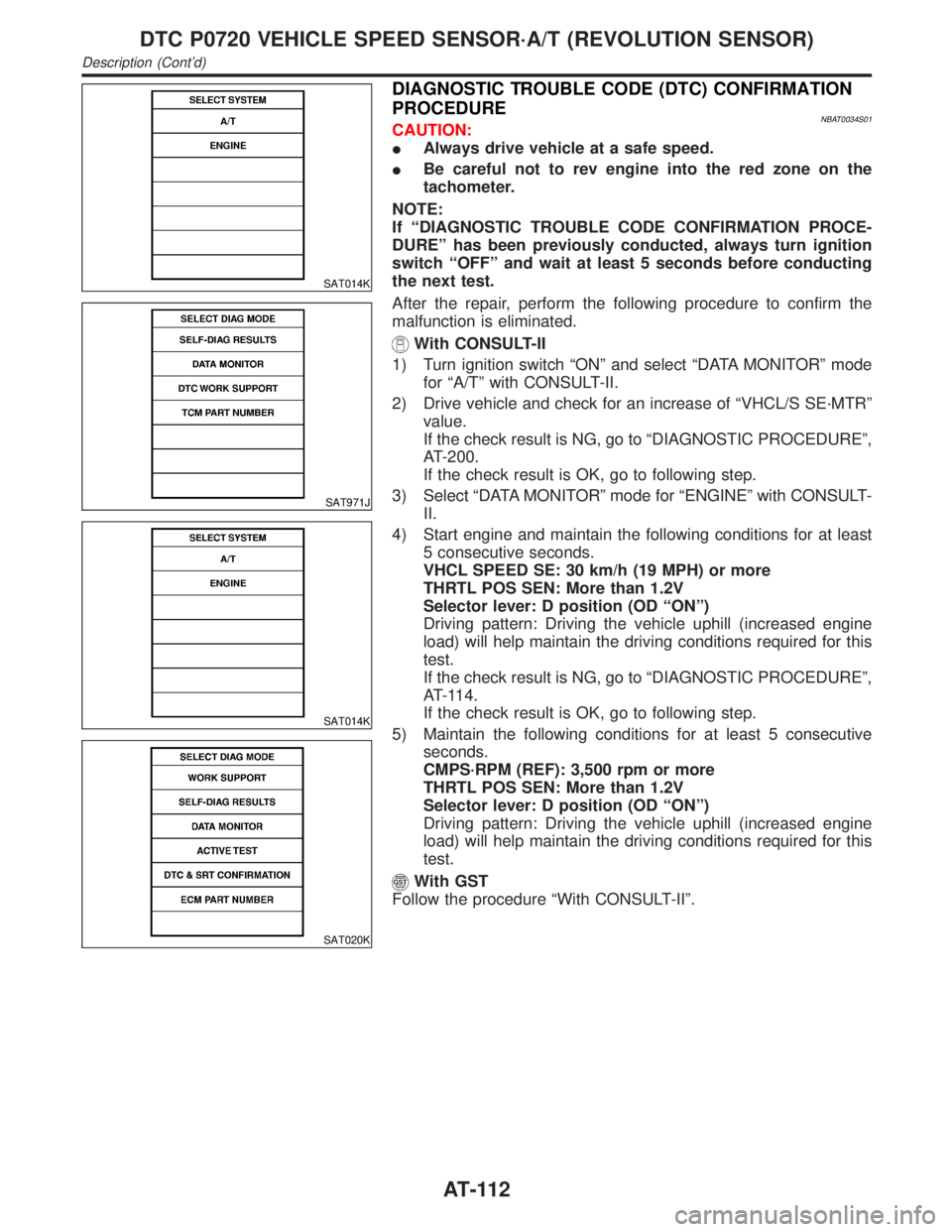
SAT014K
SAT971J
SAT014K
SAT020K
DIAGNOSTIC TROUBLE CODE (DTC) CONFIRMATION
PROCEDURE
NBAT0034S01CAUTION:
IAlways drive vehicle at a safe speed.
IBe careful not to rev engine into the red zone on the
tachometer.
NOTE:
If ªDIAGNOSTIC TROUBLE CODE CONFIRMATION PROCE-
DUREº has been previously conducted, always turn ignition
switch ªOFFº and wait at least 5 seconds before conducting
the next test.
After the repair, perform the following procedure to confirm the
malfunction is eliminated.
With CONSULT-II
1) Turn ignition switch ªONº and select ªDATA MONITORº mode
for ªA/Tº with CONSULT-II.
2) Drive vehicle and check for an increase of ªVHCL/S SE´MTRº
value.
If the check result is NG, go to ªDIAGNOSTIC PROCEDUREº,
AT-200.
If the check result is OK, go to following step.
3) Select ªDATA MONITORº mode for ªENGINEº with CONSULT-
II.
4) Start engine and maintain the following conditions for at least
5 consecutive seconds.
VHCL SPEED SE: 30 km/h (19 MPH) or more
THRTL POS SEN: More than 1.2V
Selector lever: D position (OD ªONº)
Driving pattern: Driving the vehicle uphill (increased engine
load) will help maintain the driving conditions required for this
test.
If the check result is NG, go to ªDIAGNOSTIC PROCEDUREº,
AT-114.
If the check result is OK, go to following step.
5) Maintain the following conditions for at least 5 consecutive
seconds.
CMPS´RPM (REF): 3,500 rpm or more
THRTL POS SEN: More than 1.2V
Selector lever: D position (OD ªONº)
Driving pattern: Driving the vehicle uphill (increased engine
load) will help maintain the driving conditions required for this
test.
With GST
Follow the procedure ªWith CONSULT-IIº.
DTC P0720 VEHICLE SPEED SENSOR´A/T (REVOLUTION SENSOR)
Description (Cont'd)
AT-112