engine INFINITI QX4 2001 Factory Service Manual
[x] Cancel search | Manufacturer: INFINITI, Model Year: 2001, Model line: QX4, Model: INFINITI QX4 2001Pages: 2395, PDF Size: 43.2 MB
Page 975 of 2395

System DescriptionNBEC0264This circuit line (LAN) is used to control the smooth shifting up and down of A/T during the hard acceleration/
deceleration.
Pulse signals are exchanged between ECM and TCM (Transmission Control Module).
Be sure to erase the malfunction information such as DTC not only in TCM but also ECM after the A/T
related repair.
ECM Terminals and Reference ValueNBEC0672Specification data are reference values and are measured between each terminal and ground.
CAUTION:
Do not use ECM ground terminals when measuring input/output voltage. Doing so may result in dam-
age to the ECM's transistor. Use a ground other than ECM terminals, such as the ground.
TERMI-
NAL
NO.WIRE
COLORITEM CONDITION DATA (DC Voltage)
114 G/RCommunication line
(LAN)[Engine is running]
IIdle speedApproximately 2V
On Board Diagnosis LogicNBEC0266Malfunction is detected when ECM receives incorrect voltage from
TCM (Transmission Control Module) continuously.
Possible CauseNBEC0517IHarness or connectors
[The communication line circuit between ECM and TCM
(Transmission Control Module) is open or shorted.]
ITCM
IDead (Weak) battery
SEF058Y
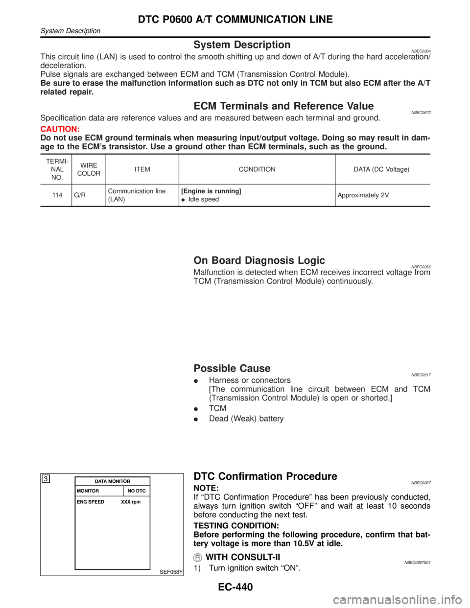
DTC Confirmation ProcedureNBEC0267NOTE:
If ªDTC Confirmation Procedureº has been previously conducted,
always turn ignition switch ªOFFº and wait at least 10 seconds
before conducting the next test.
TESTING CONDITION:
Before performing the following procedure, confirm that bat-
tery voltage is more than 10.5V at idle.
WITH CONSULT-IINBEC0267S011) Turn ignition switch ªONº.
DTC P0600 A/T COMMUNICATION LINE
System Description
EC-440
Page 976 of 2395

2) Select ªDATA MONITORº mode with CONSULT-II.
3) Start engine and let it idle for at least 2 seconds.
4) If DTC is detected, go to ªDiagnostic Procedureº, EC-443.
GI
MA
EM
LC
FE
AT
TF
PD
AX
SU
BR
ST
RS
BT
HA
SC
EL
IDX
DTC P0600 A/T COMMUNICATION LINE
DTC Confirmation Procedure (Cont'd)
EC-441
Page 979 of 2395

SEC220B
Component DescriptionNBEC0271The ECM consists of a microcomputer and connectors for signal
input and output and for power supply. The unit controls the engine.
On Board Diagnosis LogicNBEC0272Malfunction is detected when ECM calculation function is
malfunctioning.
Possible CauseNBEC0518IECM
DTC Confirmation ProcedureNBEC0273NOTE:
If ªDTC Confirmation Procedureº has been previously conducted,
always turn ignition switch ªOFFº and wait at least 10 seconds
before conducting the next test.
SEF058Y
WITH CONSULT-IINBEC0273S011) Turn ignition switch ªONº.
2) Select ªDATA MONITORº mode with CONSULT-II.
3) Start engine.
4) Run engine for at least 30 seconds at idle speed.
5) If 1st trip DTC is detected, go to ªDiagnostic Procedureº,
EC-445.
WITH GSTNBEC0273S02Follow the procedure ªWITH CONSULT-IIº above.
DTC P0605 ECM
Component Description
EC-444
Page 981 of 2395

DescriptionNBEC0691SYSTEM DESCRIPTIONNBEC0691S01
Sensor Input signal to ECM function ECM Actuator
Crankshaft positon sensor (POS) Engine speed (POS)
Intake valve
timing con-
trolIntake valve timing control sole-
noid valve Crankshaft position sensor (REF) Engine speed (REF)
Camshaft position sensor Engine speed
Engine coolant temperature sensor Engine coolant temperature
Vehicle speed sensor Vehicle speed
JEF349Z
This mechanism hydraulically controls cam phases continuously with the fixed operating angle of the intake
valve.
The ECM receives signals such as crankshaft position, camshaft position, engine speed, and engine coolant
temperature. Then, the ECM sends ON/OFF pulse duty signals to the camshaft timing control valve depend-
ing on driving status. This makes it possible to control the shut/open timing of the intake valve to increase
engine torque in low/mid speed range and output in high-speed range.
CONSULT-II Reference Value in Data Monitor
Mode
NBEC0692Specification data are reference values.
MONITOR ITEM CONDITION SPECIFICATION
INT/V TIM (B1)
INT/V TIM (B2)IEngine: After warming up
IShift lever ªNº
IQuickly depressed accelerator
pedal
INo-loadIdle 0É CA
2,000 rpm Approximately 12 - 18É CA
INT/V SOL (B1)
INT/V SOL (B2)IEngine: After warming up
IShift lever ªNº
IQuickly depressed accelerator
pedal
INo-loadIdle 0%
2,000 rpm Approximately 40%
DTC P1110 (RIGHT, -B1), P1135 (LEFT, -B2) INTAKE VALVE TIMING CONTROL
Description
EC-446
Page 982 of 2395

ECM Terminals and Reference Value=NBEC0693Specification data are reference values, and are measured between each terminal and ground.
CAUTION:
Do not use ECM ground terminals when measuring voltage. Doing so may result in damage to the
ECM's transistor. Use a ground other than the ECM terminals, such as the ground.
TERMI-
NAL
NO.WIRE
COLORITEM CONDITION DATA (DC Voltage)
13 OR/BIntake valve timing
control solenoid valves
(RH)[Engine is running]
IWarm-up condition
IIdle speedBattery voltage
[Engine is running]
IWarm-up condition
IEngine speed is 2,000 rpm.7-8V
SEF350Z
15 P/LIntake valve timing
control solenoid valves
(LH)[Engine is running]
IWarm-up condition
IIdle speedBattery voltage
[Engine is running]
IWarm-up condition
IEngine speed is 2,000 rpm.7-8V
SEF350Z
79 Y/GIntake valve timing
control position sen-
sors (RH)[Engine is running]
IWarm-up condition
IIdle speedApproximately 0.5VSEF351Z
[Engine is running]
IWarm-up condition
IEngine speed is 2,000 rpm.Approximately 0.5V
SEF352Z
GI
MA
EM
LC
FE
AT
TF
PD
AX
SU
BR
ST
RS
BT
HA
SC
EL
IDX
DTC P1110 (RIGHT, -B1), P1135 (LEFT, -B2) INTAKE VALVE TIMING CONTROL
ECM Terminals and Reference Value
EC-447
Page 983 of 2395
![INFINITI QX4 2001 Factory Service Manual TERMI-
NAL
NO.WIRE
COLORITEM CONDITION DATA (DC Voltage)
89 ORIntake valve timing
control position sen-
sors (LH)[Engine is running]
IWarm-up condition
IIdle speedApproximately 0.5V
SEF351Z
[Engine is INFINITI QX4 2001 Factory Service Manual TERMI-
NAL
NO.WIRE
COLORITEM CONDITION DATA (DC Voltage)
89 ORIntake valve timing
control position sen-
sors (LH)[Engine is running]
IWarm-up condition
IIdle speedApproximately 0.5V
SEF351Z
[Engine is](/img/42/57027/w960_57027-982.png)
TERMI-
NAL
NO.WIRE
COLORITEM CONDITION DATA (DC Voltage)
89 ORIntake valve timing
control position sen-
sors (LH)[Engine is running]
IWarm-up condition
IIdle speedApproximately 0.5V
SEF351Z
[Engine is running]
IWarm-up condition
IEngine speed is 2,000 rpm.Approximately 0.5V
SEF352Z
On Board Diagnosis LogicNBEC0694Malfunction is detected when:
(Malfunction A)
The alignment of the intake valve timing control has been misreg-
istered.
(Malfunction B)
There is a gap between angle of target and phase-control angle
degree.
FAIL-SAFE MODENBEC0694S01When malfunction A or B is detected, the ECM enters fail-safe
mode and the MIL lights up.
Detected items Engine operating condition in fail-safe mode
Intake valve timing control The signal is not energized to the solenoid valve and the valve control does not function.
Possible CauseNBEC0695MALFUNCTION A OR BNBEC0695S01IHarness or connectors
(Intake valve timing control position sensor circuit is open or
shorted.) Refer to EC-482.
ICrankshaft position sensor (REF)
ICrankshaft position sensor (POS)
ICamshaft position sensor (PHASE)
DTC P1110 (RIGHT, -B1), P1135 (LEFT, -B2) INTAKE VALVE TIMING CONTROL
ECM Terminals and Reference Value (Cont'd)
EC-448
Page 984 of 2395

DTC Confirmation ProcedureNBEC0696CAUTION:
Always drive at a safe speed.
NOTE:
IIf both DTC P1111(B1), P1136 (B2) or P1140 (B1), P1145
(B2) and P1110 (B1), P1135 (B2) are displayed, perform
trouble diagnosis for ªDTC P1111(B1), P1136 (B2) or
P1140 (B1), P1145 (B2)º first. (See EC-451, 482.)
IIf ªDTC Confirmation Procedureº has been previously
conducted, always turn ignition switch ªOFFº and wait at
least 10 seconds before conducting the next test.
SEF353Z
PROCEDURE FOR MALFUNCTION ANBEC0696S01With CONSULT-IINBEC0696S01011) Turn ignition switch ªONº.
2) Select ªDATA MONITORº mode with CONSULT-II.
3) Maintain the following conditions for at least 10 consecutive
seconds.
ENG SPEED More than 2,000 rpm
COOLANT TEMPS More than 70ÉC (158ÉF)
Selector lever 1st position
Driving locationDriving vehicle uphill
(Increased engine load will help main-
tain the driving conditions required for
this test.)
4) Maintain the following conditions for at least 20 consecutive
seconds.
ENG SPEED Idle
COOLANT TEMPS More than 70ÉC (158ÉF)
Selector lever ªPº or ªNº position
5) If 1st trip DTC is detected, go to ªP1140, P1145 INTAKE
VALVE TIMING CONTROL POSITION SENSORº. Refer to
EC-482.
With GSTNBEC0696S0102Follow the procedure ªWith CONSULT-IIº above.
GI
MA
EM
LC
FE
AT
TF
PD
AX
SU
BR
ST
RS
BT
HA
SC
EL
IDX
DTC P1110 (RIGHT, -B1), P1135 (LEFT, -B2) INTAKE VALVE TIMING CONTROL
DTC Confirmation Procedure
EC-449
Page 985 of 2395

SEF353Z
PROCEDURE FOR MALFUNCTION B=NBEC0696S02With CONSULT-IINBEC0696S02011) Turn ignition switch ªONº.
2) Select ªDATA MONITORº mode with CONSULT-II.
3) Maintain the following conditions for at least 20 consecutive
seconds.
ENG SPEED2,000 - 3,000 rpm (A constant rotation
is maintained.)
COOLANT TEMPS 70 - 90ÉC (158 - 194ÉF)
Selector lever 1st or position
Driving location uphillDriving vehicle uphill
(Increased engine load will help main-
tain the driving conditions required for
this test.)
4) If 1st trip DTC is detected, go to ªP1140, P1145 INTAKE
VALVE TIMING CONTROL POSITION SENSORº. Refer to
EC-482.
With GSTNBEC0696S0202Follow the procedure ªWith CONSULT-IIº above.
DTC P1110 (RIGHT, -B1), P1135 (LEFT, -B2) INTAKE VALVE TIMING CONTROL
DTC Confirmation Procedure (Cont'd)
EC-450
Page 986 of 2395

SEF354Z
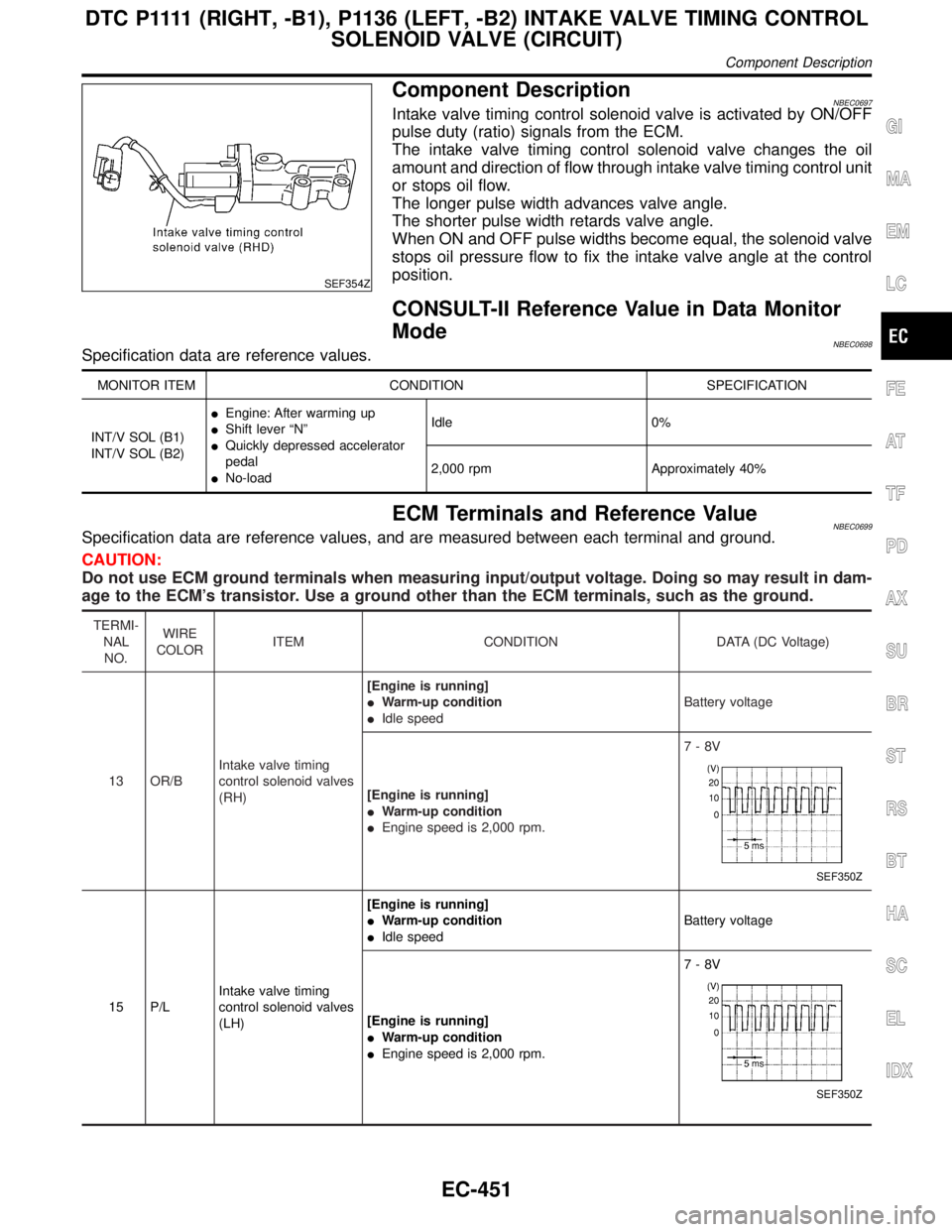
Component DescriptionNBEC0697Intake valve timing control solenoid valve is activated by ON/OFF
pulse duty (ratio) signals from the ECM.
The intake valve timing control solenoid valve changes the oil
amount and direction of flow through intake valve timing control unit
or stops oil flow.
The longer pulse width advances valve angle.
The shorter pulse width retards valve angle.
When ON and OFF pulse widths become equal, the solenoid valve
stops oil pressure flow to fix the intake valve angle at the control
position.
CONSULT-II Reference Value in Data Monitor
Mode
NBEC0698Specification data are reference values.
MONITOR ITEM CONDITION SPECIFICATION
INT/V SOL (B1)
INT/V SOL (B2)IEngine: After warming up
IShift lever ªNº
IQuickly depressed accelerator
pedal
INo-loadIdle 0%
2,000 rpm Approximately 40%
ECM Terminals and Reference ValueNBEC0699Specification data are reference values, and are measured between each terminal and ground.
CAUTION:
Do not use ECM ground terminals when measuring input/output voltage. Doing so may result in dam-
age to the ECM's transistor. Use a ground other than the ECM terminals, such as the ground.
TERMI-
NAL
NO.WIRE
COLORITEM CONDITION DATA (DC Voltage)
13 OR/BIntake valve timing
control solenoid valves
(RH)[Engine is running]
IWarm-up condition
IIdle speedBattery voltage
[Engine is running]
IWarm-up condition
IEngine speed is 2,000 rpm.7-8V
SEF350Z
15 P/LIntake valve timing
control solenoid valves
(LH)[Engine is running]
IWarm-up condition
IIdle speedBattery voltage
[Engine is running]
IWarm-up condition
IEngine speed is 2,000 rpm.7-8V
SEF350Z
GI
MA
EM
LC
FE
AT
TF
PD
AX
SU
BR
ST
RS
BT
HA
SC
EL
IDX
D T C P 1111(RIGHT, -B1), P1136 (LEFT, -B2) INTAKE VALVE TIMING CONTROL
SOLENOID VALVE (CIRCUIT)
Component Description
EC-451
Page 987 of 2395

On Board Diagnosis LogicNBEC0700Malfunction is detected when an improper voltage is sent to the
ECM through intake valve timing control solenoid valve.
Possible CauseNBEC0701IHarness or connectors
(Intake valve timing control solenoid valve circuit is open or
shorted.)
IIntake valve timing control solenoid valve.
SEF353Z
DTC Confirmation ProcedureNBEC0702NOTE:
If ªDTC Confirmation Procedureº has been previously
conducted, always turn ignition switch ªOFFº and wait at least
10 seconds before conducting the next test.
WITH CONSULT-IINBEC0702S011) Turn ignition switch ªONº.
2) Select ªDATA MONITORº mode with CONSULT-II.
3) Maintain the following conditions for at least 5 seconds.
Engine speed More than Idle speed
Selector lever ªPº or ªNº position
4) If 1st trip DTC is detected, go to ªDiagnostic Procedureº,
EC-455.
WITH GSTNBEC0702S02Follow the procedure ªWith CONSULT-IIº above.
D T C P 1111(RIGHT, -B1), P1136 (LEFT, -B2) INTAKE VALVE TIMING CONTROL
SOLENOID VALVE (CIRCUIT)
On Board Diagnosis Logic
EC-452