rotor INFINITI QX4 2001 Factory Workshop Manual
[x] Cancel search | Manufacturer: INFINITI, Model Year: 2001, Model line: QX4, Model: INFINITI QX4 2001Pages: 2395, PDF Size: 43.2 MB
Page 2003 of 2395

CHASSIS AND BODY MAINTENANCENBMA0004S0102
Abbreviations: R = Replace. I = Inspect. Correct or replace if necessary. L = Lubricate
MAINTENANCE OPERATIONMAINTENANCE INTERVAL
Reference
Section
- Page or
- Content Title Perform at number of miles, kilo-
meters or months, whichever
comes first.Miles x 1,000
(km x 1,000)
Months3.75
(6)
37.5
(12)
611.25
(18)
915
(24)
1218.75
(30)
1522.5
(36)
1826.25
(42)
2130
(48)
2433.75
(54)
2737.5
(60)
3041.25
(66)
3345
(72)
3648.75
(78)
3952.5
(84)
4256.25
(90)
4560
(96)
48
Brake lines & cables I I I I MA-25
Brake pads, rotors, drums & linings I IIIIIIIMA-25, 26
Automatic transmission & all-mode
4WD transfer fluid & differential
gear oil (exc. LSD)NOTE (1) I I I I MA-21, 22, 23
LSD gear oil NOTE (1) I R I R MA-24
Steering gear, linkage & transfer
gear, axle & suspension partsIIIIIIIIMA-26
NOTE (6)
Tire rotation NOTE (2)MA-4
Drive shaft boots (
) IIIIIIIIAX-10, ªDrive
Shaftº
Propeller shaft NOTE (3) L LLLLLLLMA-23
Front wheel bearing grease (4x2) I I
Front wheel bearing
grease (
)NOTE (4) I R I RAX-4, ªFront
Wheel Bearingº
Exhaust system I IIIIIIIMA-21
Supplemental air bag systems NOTE (5)RS-14, ªMainte-
nance Itemsº
Ventilation air filter I RIRIRIRHA-159, ªVentila-
tion Air Filterº
ASCD vacuum hoses I I I IEL-237, ªASCD
ACTUATOR/
PUMP CHECKº
NOTE:
(1) If towing a trailer, using a camper or a car-top carrier, or driving on rough or muddy roads, change (not just inspect) fluid (A/T, all mode 4WD transfer)/differential gear oil (exc.
LSD) at every 30,000 miles (48,000 km) or 24 months, and change LSD gear oil every 15,000 miles (24,000 km) or 12 months.
(2) Refer to ªTire rotationº under the ªGENERAL MAINTENANCEº heading earlier in this section.
(3) The propeller shaft should be re-greased after being immersed in water.
(4) If operating frequently in water, replace grease every 3,750 miles (6,000 km) or 3 months.
(5) Inspect the air bag system 10 years after the date of manufacture noted on the FMVSS certification label.
(6) Refer to SU-5, ªFront Suspension Partsº and SU-16, ªRear Suspension Partsº, AX-3, ªFront Axle Partsº and AX-18, ªRear Axle Partsº.
PERIODIC MAINTENANCE
Schedule 1 (Cont'd)
MA-8
Page 2005 of 2395

CHASSIS AND BODY MAINTENANCENBMA0004S0202
Abbreviations: R = Replace. I = Inspect. Correct or replace if necessary. L = Lubricate
MAINTENANCE OPERATIONMAINTENANCE INTERVAL
Reference Section
- Page
or
- Content Title Perform at number of miles, kilometers
or months, whichever comes first.Miles x 1,000
(km x 1,000)
Months7.5
(12)
615
(24)
1222.5
(36)
1830
(48)
2437.5
(60)
3045
(72)
3652.5
(84)
4260
(96)
48
Brake lines & cablesIIIIMA-25
Brake pads, rotors, drums & liningsIIIIMA-25, 26
Automatic transmission & all-mode 4WD
transfer fluid & differential gear oil (exc.
LSD)IIIIMA-21, 22, 23
LSD gear oilIRIRMA-24
Steering gear, linkage & transfer gear,
axle & suspension partsIIMA-26
NOTE (4)
Tire rotation NOTE (1)MA-4
Drive shaft boots (
) IIIIAX-10, ªDrive shaftº
Propeller shaft NOTE (2)LLLLMA-23
Front wheel bearing grease (4x2) I I
Front wheel bearing grease (
) IRIRAX-4, ªFront Wheel
Bearingº
Exhaust systemI I MA-21
Supplemental air bag systems NOTE (3)RS-14, ªMaintenance
Itemº
Ventilation air filterRRRRHA-159, ªVentilation Air
Filterº
ASCD vacuum hosesIIIIEL-237, ªASCD
ACTUATOR/PUMP
CHECKº
NOTE:
(1) Refer to ªTire rotationº under the ªGENERAL MAINTENANCEº heading earlier in this section.
(2) The propeller shaft should be re-greased after being immersed in water.
(3) Inspect the air bag system 10 years after the date of manufacture noted on the FMVSS certification label.
(4) Refer to SU-5, ªFront Suspension Partsº and SU-16, ªRear Suspension Partsº, AX-3, ªFront Axle Partsº and AX-18, ªRear Axle Partsº.
PERIODIC MAINTENANCE
Schedule 2 (Cont'd)
MA-10
Page 2020 of 2395

SBR451D
Checking Brake Fluid Level and LeaksNBMA0030If fluid level is extremely low, check brake system for leaks.
SBR389C
Checking Brake Lines and CablesNBMA0031Check brake fluid lines and parking brake cables for improper
attachment, leaks, chafing, abrasions and deterioration.
SMA260A
Checking Disc BrakeNBMA0032ROTORNBMA0032S01Check condition and thickness.
Standard thickness:
28 mm (1.10 in)
Minimum thickness:
26 mm (1.02 in)
SMA922A
CALIPERNBMA0032S02Check for leakage.
SMA847B
PADNBMA0032S03Check wear or damage.
Standard thickness:
11 mm (0.43 in)
Minimum thickness:
2 mm (0.08 in)
GI
EM
LC
EC
FE
AT
TF
PD
AX
SU
BR
ST
RS
BT
HA
SC
EL
IDX
CHASSIS AND BODY MAINTENANCE
Checking Brake Fluid Level and Leaks
MA-25
Page 2180 of 2395

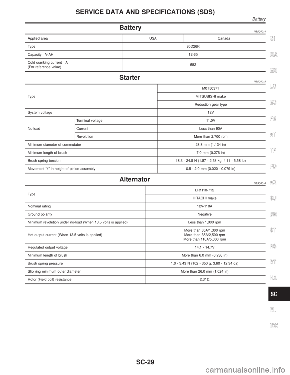
BatteryNBSC0014
Applied area USA Canada
Type80D26R
Capacity V-AH12-65
Cold cranking current A
(For reference value)582
StarterNBSC0015
TypeM0T50371
MITSUBISHI make
Reduction gear type
System voltage12V
No-loadTerminal voltage 11.0V
Current Less than 90A
Revolution More than 2,700 rpm
Minimum diameter of commutator28.8 mm (1.134 in)
Minimum length of brush7.0 mm (0.276 in)
Brush spring tension18.3 - 24.8 N (1.87 - 2.53 kg, 4.11 - 5.58 lb)
Movement ªº in height of pinion assembly 0.5 - 2.0 mm (0.020 - 0.079 in)
AlternatorNBSC0016
TypeLR1110-712
HITACHI make
Nominal rating12V-110A
Ground polarityNegative
Minimum revolution under no-load (When 13.5 volts is applied) Less than 1,000 rpm
Hot output current (When 13.5 volts is applied)More than 35A/1,300 rpm
More than 85A/2,500 rpm
More than 110A/5,000 rpm
Regulated output voltage14.1 - 14.7V
Minimum length of brushMore than 6.0 mm (0.236 in)
Brush spring pressure 1.0 - 3.43 N (102 - 350 g, 3.60 - 12.34 oz)
Slip ring minimum outer diameter More than 26.0 mm (1.024 in)
Rotor (Field coil) resistance2.31W
GI
MA
EM
LC
EC
FE
AT
TF
PD
AX
SU
BR
ST
RS
BT
HA
EL
IDX
SERVICE DATA AND SPECIFICATIONS (SDS)
Battery
SC-29
Page 2208 of 2395

ComponentsNBST0032
SST924C
1. Pulley
2. Front bracket
3. Oil seal
4. Suction pipe
5. O-ring
6. Casing
7. Flow control valve spring
8. Flow control A valve9. Dowel pin
10. Flow control B valve assembly
11. Side plate (Front)
12. Cam ring
13. Rotor
14. Vane
15. Snap ring16. Side plate (Rear)
17. Side plate inner seal
18. Side plate outer seal
19. O-ring
20. Rear cover
21. Power steering pump bracket
22. Copper washer
SST925C
Pre-disassembly InspectionNBST0033Disassemble the power steering oil pump only if the following items
are found.
IOil leak from any point shown in the figure.
IDeformed or damaged pulley.
IPoor performance.
GI
MA
EM
LC
EC
FE
AT
TF
PD
AX
SU
BR
RS
BT
HA
SC
EL
IDX
POWER STEERING OIL PUMP
Components
ST-27
Page 2209 of 2395

DisassemblyNBST0034CAUTION:
IParts which can be disassembled are strictly limited.
Never disassemble parts other than those specified.
IDisassemble in as clean a place as possible.
IClean your hands before disassembly.
IDo not use rags; use nylon cloths or paper towels.
IFollow the procedures and cautions in the Service
Manual.
IWhen disassembling and reassembling, do not let foreign
matter enter or contact the parts.
1. Fix power steering pump to vise.
CAUTION:
When fixing the pump to vise, use an aluminum plate or such
to avoid damaging the fitting plane of the steering pump.
2. Remove the front bracket mounting bolt, and remove the front
bracket from the casing.
3. Remove the rear cover mounting bolt, and remove the rear
cover from the casing.
4. Remove the O-ring from the casing.
SST926C
5. Remove side plate (rear side) from cam ring, then remove side
plate inner/outer seals from side plate (rear side).
6. Remove rotor snap ring using snap ring pliers, and remove
pulley from casing.
CAUTION:
Do not damage pulley shaft when removing rotor snap ring.
SST928C
7. Remove the followings from casing.
ICam ring
IRotor
IVane
ISide plate (front side)
IFlow control A valve
IFlow control valve spring
IFlow control B valve assembly
CAUTION:
Be careful not to drop flow control valve.
8. Remove inlet connector mounting bolt, and remove inlet con-
nector from casing.
9. Remove inlet connector seal from inlet connector.
10. Remove drive shaft seal from casing with a screwdriver.
CAUTION:
Do not damage casing surface with the screwdriver.
POWER STEERING OIL PUMP
Disassembly
ST-28
Page 2210 of 2395

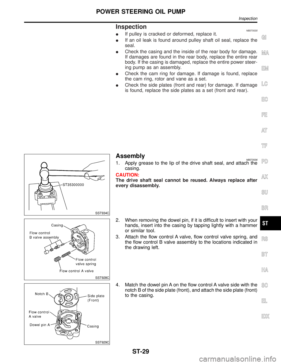
InspectionNBST0035IIf pulley is cracked or deformed, replace it.
IIf an oil leak is found around pulley shaft oil seal, replace the
seal.
ICheck the casing and the inside of the rear body for damage.
If damages are found in the rear body, replace the entire rear
body. If the casing is damaged, replace the entire power steer-
ing pump as an assembly.
ICheck the cam ring for damage. If damage is found, replace
the cam ring, rotor and vane as a set.
ICheck the side plates (front and rear) for damage. If damage
is found, replace the side plates as a set (front and rear).
SST934C
AssemblyNBST00361. Apply grease to the lip of the drive shaft seal, and attach the
casing.
CAUTION:
The drive shaft seal cannot be reused. Always replace after
every disassembly.
SST928C
2. When removing the dowel pin, if it is difficult to insert with your
hands, insert into the casing by tapping lightly with a hammer
or similar tool.
3. Attach the flow control A valve, flow control valve spring, and
the flow control B valve assembly to the locations indicated in
the drawing left.
SST929C
4. Match the dowel pin A on the flow control A valve side with the
notch B of the side plate (front), and attach the side plate (front)
to the casing.
GI
MA
EM
LC
EC
FE
AT
TF
PD
AX
SU
BR
RS
BT
HA
SC
EL
IDX
POWER STEERING OIL PUMP
Inspection
ST-29
Page 2211 of 2395

SST930C
5. Face the cam ring side with fewer pores towards the casing,
and attach the cam ring on top of the side plate (front).
6. Attach the pulley to the casing.
CAUTION:
Attach with care so as not to damage the drive shaft seal.
SST289A
7. Face the side of the rotor with the punch mark towards the
casing, and attach the rotor to the pulley shaft.
SST843A
8. Attach the vane to the rotor so that the vane's arc touches the
cam ring.
SST931C
9. Use a hammer or suitable tool to insert the rotor snap ring into
the pulley shaft channel.
CAUTION:
IThe rotor snap ring cannot be reused. Always replace after
every disassembly.
IInsert with care so as not to damage the rotor or the pul-
ley shaft.
IIf the rotor is damaged, replace the power steering as an
assembly.
SST932C
10. Match the dowel pin A on the flow control A valve side with the
notch B of the side plate (rear), and attach the side plate (rear)
to the cam ring.
11. Apply Genuine Nissan PSF II or equivalent to O-ring and
attach to the casing.
CAUTION:
The O-ring cannot be reused. Always replace after every dis-
assembly.
POWER STEERING OIL PUMP
Assembly (Cont'd)
ST-30