rotor INFINITI QX4 2001 Factory Service Manual
[x] Cancel search | Manufacturer: INFINITI, Model Year: 2001, Model line: QX4, Model: INFINITI QX4 2001Pages: 2395, PDF Size: 43.2 MB
Page 302 of 2395

Oil Pump
COMPONENTSNBAT0112
SAT648AB
SAT649A
DISASSEMBLYNBAT01131. Loosen bolts in numerical order and remove oil pump cover.
SAT650A
2. Remove rotor, vane rings and vanes.
IInscribe a mark on back of rotor for identification of fore-
aft direction when reassembling rotor. Then remove rotor.
SAT651A
3. While pushing on cam ring remove pivot pin.
IBe careful not to scratch oil pump housing.
GI
MA
EM
LC
EC
FE
TF
PD
AX
SU
BR
ST
RS
BT
HA
SC
EL
IDX
REPAIR FOR COMPONENT PARTS
Oil Pump
AT-297
Page 303 of 2395

SAT652A
4. While holding cam ring and spring lift out cam ring spring.
IBe careful not to damage oil pump housing.
IHold cam ring spring to prevent it from jumping.
SAT653A
5. Remove cam ring and cam ring spring from oil pump housing.
SAT654A
6. Remove pivot pin from control piston and remove control pis-
ton assembly.
SAT655A
7. Remove oil seal from oil pump housing.
IBe careful not to scratch oil pump housing.
SAT656A
INSPECTIONNBAT0114Oil Pump Cover, Rotor, Vanes, Control Piston, Side
Seals, Cam Ring and Friction Ring
NBAT0114S01ICheck for wear or damage.
REPAIR FOR COMPONENT PARTS
Oil Pump (Cont'd)
AT-298
Page 304 of 2395

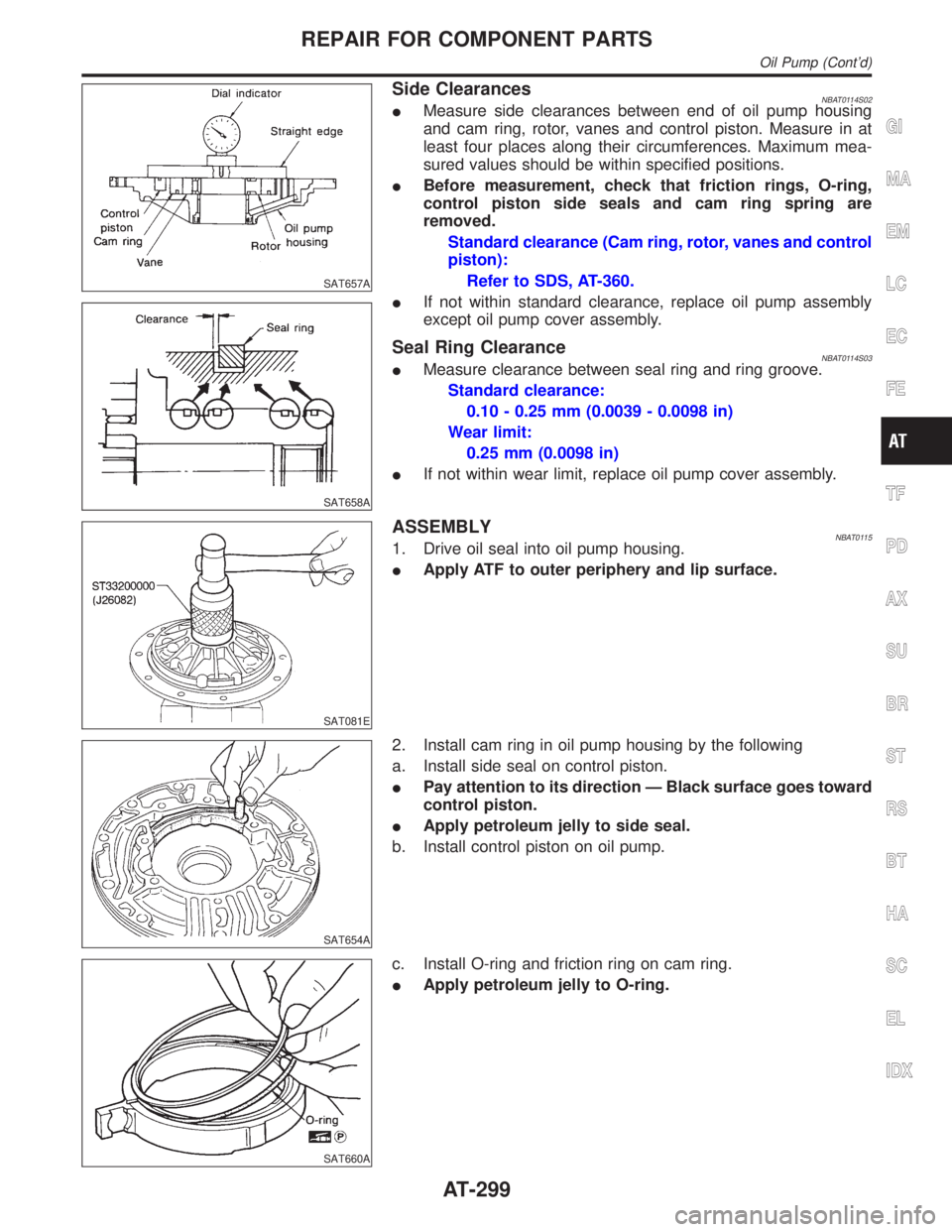
SAT657A
SAT658A
Side ClearancesNBAT0114S02IMeasure side clearances between end of oil pump housing
and cam ring, rotor, vanes and control piston. Measure in at
least four places along their circumferences. Maximum mea-
sured values should be within specified positions.
IBefore measurement, check that friction rings, O-ring,
control piston side seals and cam ring spring are
removed.
Standard clearance (Cam ring, rotor, vanes and control
piston):
Refer to SDS, AT-360.
IIf not within standard clearance, replace oil pump assembly
except oil pump cover assembly.
Seal Ring ClearanceNBAT0114S03IMeasure clearance between seal ring and ring groove.
Standard clearance:
0.10 - 0.25 mm (0.0039 - 0.0098 in)
Wear limit:
0.25 mm (0.0098 in)
IIf not within wear limit, replace oil pump cover assembly.
SAT081E
ASSEMBLYNBAT01151. Drive oil seal into oil pump housing.
IApply ATF to outer periphery and lip surface.
SAT654A
2. Install cam ring in oil pump housing by the following
a. Install side seal on control piston.
IPay attention to its direction Ð Black surface goes toward
control piston.
IApply petroleum jelly to side seal.
b. Install control piston on oil pump.
SAT660A
c. Install O-ring and friction ring on cam ring.
IApply petroleum jelly to O-ring.
GI
MA
EM
LC
EC
FE
TF
PD
AX
SU
BR
ST
RS
BT
HA
SC
EL
IDX
REPAIR FOR COMPONENT PARTS
Oil Pump (Cont'd)
AT-299
Page 305 of 2395

SAT661A
d. Assemble cam ring, cam ring spring and spring seat. Install
spring by pushing it against pump housing.
SAT651A
e. While pushing on cam ring install pivot pin.
SAT662A
3. Install rotor, vanes and vane rings.
IPay attention to direction of rotor.
SAT649A
4. Install oil pump housing and oil pump cover.
a. Wrap masking tape around splines of oil pump cover assem-
bly to protect seal. Position oil pump cover assembly in oil
pump housing assembly, then remove masking tape.
b. Tighten bolts in a criss-cross pattern.
SAT663A
5. Install new seal rings carefully after packing ring grooves with
petroleum jelly. Press rings down into jelly to a close fit.
ISeal rings come in two different diameters. Check fit care-
fully in each groove.
Small dia. seal ring:
No mark
Large dia. seal ring:
Yellow mark in area shown by arrow
IDo not spread gap of seal ring excessively while install-
ing. It may deform ring.
REPAIR FOR COMPONENT PARTS
Oil Pump (Cont'd)
AT-300
Page 365 of 2395

LOW & REVERSE BRAKENBAT0167S05
Code number4EX16 4EX17
Number of drive plates8
Number of driven plates8
Thickness of drive plate mm (in)Standard 1.90 - 2.05 (0.0748 - 0.0807) 1.52 - 1.67 (0.0598 - 0.0657)
Wear limit 1.40 (0.0551)
Clearance mm (in)Standard 0.8 - 1.1 (0.031 - 0.043)
Allowable limit 2.7 (0.106)
Thickness of retaining plateThickness mm (in) Part number*
7.6 (0.299)
7.8 (0.307)
8.0 (0.315)
8.2 (0.323)
8.4 (0.331)
8.6 (0.339)
8.8 (0.346)
9.0 (0.354)
9.2 (0.362)
9.4 (0.370)
9.6 (0.378)31667-41X07
31667-41X08
31667-41X00
31667-41X01
31667-41X02
31667-41X03
31667-41X04
31667-41X05
31667-41X06
31667-41X09
31667-41X10
BRAKE BANDNBAT0167S06
Anchor end bolt nut tightening torque 40 - 51 N´m (4.1 - 5.2 kg-m, 30 - 38 ft-lb)
Anchor end bolt tightening torque4 - 6 N´m (0.4 - 0.6 kg-m, 35 - 52 in-lb)
Number of returning revolution for anchor end bolt 2.5
Oil Pump and Low One-way ClutchNBAT0168Unit: mm (in)
Oil pump clearanceCam ring Ð oil pump housing Standard 0.01 - 0.024 (0.0004 - 0.0009)
Rotor, vanes and control piston Ð oil
pump housingStandard 0.03 - 0.044 (0.0012 - 0.0017)
Seal ring clearanceStandard 0.10 - 0.25 (0.0039 - 0.0098)
Allowable limit 0.25 (0.0098)
Total End PlayNBAT0169
Total end play ªT1º 0.25 - 0.55 mm (0.0098 - 0.0217 in)
Thickness of oil pump cover bearing raceThickness mm (in) Part number*
0.8 (0.031)
1.0 (0.039)
1.2 (0.047)
1.4 (0.055)
1.6 (0.063)
1.8 (0.071)
2.0 (0.079)31435-41X01
31435-41X02
31435-41X03
31435-41X04
31435-41X05
31435-41X06
31435-41X07
SERVICE DATA AND SPECIFICATIONS (SDS)
Clutches and Brakes (Cont'd)
AT-360
Page 368 of 2395

FRONT & REAR AXLE
SECTION
AX
CONTENTS
FRONT AXLE..................................................................2
Precautions ..................................................................2
PRECAUTIONS.........................................................2
Preparation ..................................................................2
SPECIAL SERVICE TOOLS........................................2
COMMERCIAL SERVICE TOOLS................................2
Noise, Vibration and Harshness (NVH)
Troubleshooting ...........................................................3
NVH TROUBLESHOOTING CHART............................3
On-vehicle Service.......................................................3
FRONT AXLE PARTS................................................3
FRONT WHEEL BEARING.........................................4
DRIVE SHAFT...........................................................5
Wheel Hub and Rotor Disc..........................................6
COMPONENTS.........................................................6
REMOVAL.................................................................6
INSTALLATION..........................................................7
DISASSEMBLY..........................................................8
INSPECTION.............................................................8
ASSEMBLY...............................................................8
Knuckle Spindle ...........................................................9
REMOVAL.................................................................9
INSPECTION...........................................................10
INSTALLATION........................................................10
Drive Shaft .................................................................10
COMPONENTS.......................................................10
REMOVAL............................................................... 11
DISASSEMBLY........................................................ 11
INSPECTION...........................................................12
ASSEMBLY.............................................................13
INSTALLATION........................................................14
Service Data and Specifications (SDS).....................15
WHEEL BEARING (FRONT).....................................15
DRIVE SHAFT.........................................................16
REAR AXLE...................................................................17
Precautions ................................................................17
PRECAUTIONS.......................................................17
Preparation ................................................................17
SPECIAL SERVICE TOOLS......................................17
COMMERCIAL SERVICE TOOLS..............................18
Noise, Vibration and Harshness (NVH)
Troubleshooting .........................................................18
On-vehicle Service.....................................................18
REAR AXLE PARTS.................................................18
REAR WHEEL BEARING.........................................18
Components...............................................................19
Removal .....................................................................19
Inspection...................................................................21
AXLE SHAFT...........................................................21
BEARING CAGE......................................................21
REAR AXLE HOUSING............................................21
Installation ..................................................................21
Service Data and Specifications (SDS).....................22
WHEEL BEARING (REAR).......................................22
GI
MA
EM
LC
EC
FE
AT
TF
PD
SU
BR
ST
RS
BT
HA
SC
EL
IDX
Page 370 of 2395

Noise, Vibration and Harshness (NVH)
Troubleshooting
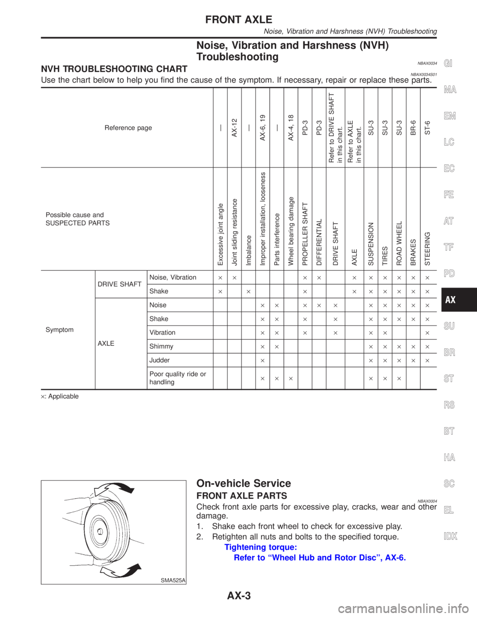
NBAX0034NVH TROUBLESHOOTING CHARTNBAX0034S01Use the chart below to help you find the cause of the symptom. If necessary, repair or replace these parts.
Reference pageÐ
AX-12
Ð
AX-6, 19
Ð
AX-4, 18
PD-3
PD-3
Refer to DRIVE SHAFT
in this chart.
Refer to AXLE
in this chart.
SU-3
SU-3
SU-3
BR-6
ST-6
Possible cause and
SUSPECTED PARTS
Excessive joint angle
Joint sliding resistance
Imbalance
Improper installation, looseness
Parts interference
Wheel bearing damage
PROPELLER SHAFT
DIFFERENTIAL
DRIVE SHAFT
AXLE
SUSPENSION
TIRES
ROAD WHEEL
BRAKES
STEERING
SymptomDRIVE SHAFTNoise, Vibration´´ ´´ ´ ´´´´´
Shake´ ´ ´ ´ ´´´´´
AXLENoise´´ ´´ ´ ´´´´´
Shake´´ ´ ´ ´´´´´
Vibration´´ ´ ´ ´´ ´
Shimmy´´ ´´´´´
Judder´ ´´´´´
Poor quality ride or
handling´´´ ´´´
´: Applicable
SMA525A
On-vehicle Service
FRONT AXLE PARTSNBAX0004Check front axle parts for excessive play, cracks, wear and other
damage.
1. Shake each front wheel to check for excessive play.
2. Retighten all nuts and bolts to the specified torque.
Tightening torque:
Refer to ªWheel Hub and Rotor Discº, AX-6.
GI
MA
EM
LC
EC
FE
AT
TF
PD
SU
BR
ST
RS
BT
HA
SC
EL
IDX
FRONT AXLE
Noise, Vibration and Harshness (NVH) Troubleshooting
AX-3
Page 373 of 2395

Wheel Hub and Rotor Disc
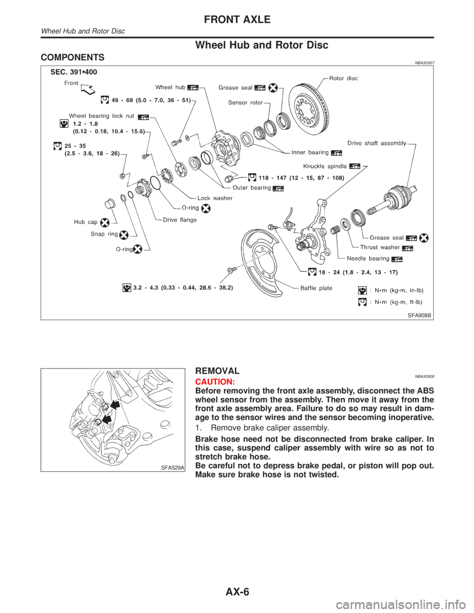
COMPONENTSNBAX0007
SFA908B
SFA529A
REMOVALNBAX0008CAUTION:
Before removing the front axle assembly, disconnect the ABS
wheel sensor from the assembly. Then move it away from the
front axle assembly area. Failure to do so may result in dam-
age to the sensor wires and the sensor becoming inoperative.
1. Remove brake caliper assembly.
Brake hose need not be disconnected from brake caliper. In
this case, suspend caliper assembly with wire so as not to
stretch brake hose.
Be careful not to depress brake pedal, or piston will pop out.
Make sure brake hose is not twisted.
FRONT AXLE
Wheel Hub and Rotor Disc
AX-6
Page 374 of 2395

SFA802B
2. Remove hub cap with suitable tool.
SFA753B
3. Remove snap ring with suitable tool.
4. Remove drive flange.
SFA364BA
5. Remove lock washer.
SFA754B
6. Remove wheel bearing lock nut.
SFA832
7. Remove wheel hub and wheel bearing.
Be careful not to drop outer bearing.
INSTALLATIONNBAX00091. After installing wheel hub and wheel bearing, adjust wheel
bearing preload.
Refer to ªPreload Adjustmentº, ªFRONT WHEEL BEARINGº,
ªOn-vehicle Serviceº, AX-4.
GI
MA
EM
LC
EC
FE
AT
TF
PD
SU
BR
ST
RS
BT
HA
SC
EL
IDX
FRONT AXLE
Wheel Hub and Rotor Disc (Cont'd)
AX-7
Page 375 of 2395

SFA755B
2. Pack drive flange groove with grease, apply grease to O-ring
(two places) and mating surface of drive flange, and install
flange.
3. Install snap ring.
SFA759B
4. Install hub cap using a suitable tool.
Do not reuse hub cap. When installing, replace it with a new
one.
FA858
DISASSEMBLYNBAX0010IRemove grease seal and bearing outer races with suitable
brass bar.
INSPECTIONNBAX0011Thoroughly clean wheel bearings and wheel hub.
Wheel BearingNBAX0011S01IMake sure wheel bearing rolls freely and is free from noise,
crack, pitting and wear.
Wheel HubNBAX0011S02ICheck wheel hub for crack by using a magnetic exploration or
dyeing test.
SFA197-A
ASSEMBLYNBAX00121. Install bearing outer race with Tool until it seats in hub.
FRONT AXLE
Wheel Hub and Rotor Disc (Cont'd)
AX-8