ignition INFINITI QX4 2001 Factory Service Manual
[x] Cancel search | Manufacturer: INFINITI, Model Year: 2001, Model line: QX4, Model: INFINITI QX4 2001Pages: 2395, PDF Size: 43.2 MB
Page 1965 of 2395

LSV (Load sensing valve) ..............................BR-12
Lubricant (R134a) A/C..................................HA-146
Lubricants .......................................................MA-11
Lubrication circuit (engine) ...............................LC-3
Lubrication-locks, hinges and hood
latches ........................................................MA-27
Luggage room lamp ........................................EL-88
M
MAFS - Wiring diagram................................EC-154
Magnet clutch .......................................HA-104, 150
MAIN - Wiring diagram.................................EC-142
Main oil pump (Transfer)...............................TF-131
Mainshaft (Transfer) ......................................TF-125
Maintenance (engine) ....................................MA-13
MAJOR OVERHALL......................................AT-281
Major overhaul (Transfer) .............................TF-120
Malfunction indicator lamp (MIL) ....................EC-74
Mass air flow sensor (MAFS) .......................EC-150
Master cylinder (brake) ..................................BR-16
Meter ...............................................................EL-94
METER - Wiring diagram................................EL-99
MIL & Data link connectors circuit ...............EC-648
MIL/DL - Wiring diagram ..............................EC-648
MIRROR - Wiring diagram............................EL-177
Mirror defogger .............................................EL-151
Mirror, door......................................................BT-56
Mirror, out side ................................................BT-56
Misfire ...........................................................EC-320
Mode door control linkage adjustment ...........HA-81
Mode door motor ............................................HA-75
Model variation ................................................GI-41
Molding - See Exterior ....................................BT-35
MULTI - Wiring diagram ................................EL-274
Multi-remote control system..........................EL-270
Multiplex communication ..............................HA-142
Multiport fuel injection (MFI) system ..............EC-28
Multiport fuel injection precautions ....................GI-6
N
NATS (Nissan anti-theft system)...................EL-328
NATS (Nissan anti-theft system)
precautions ....................................................GI-3
NATS - Wiring diagram .................................EL-330
NAVI - wiring diagram ...................................EL-394
Navigation System ........................................EL-385
Neutral-4LO switch ........................................TF-112
NVH troubleshooting (AX) ..........................AX-3, 18
NVH troubleshooting (BR)................................BR-6
NVH troubleshooting (PD)................................PD-3
NVH troubleshooting (ST).................................ST-6
NVH troubleshooting (SU) .........................SU-3, 15O
Oil change (capacity) .....................................MA-11
Oil filter (Transfer) .........................................TF-118
Oil pan (engine) .............................................EM-15
Oil pressure (engine) ........................................LC-4
Oil pump (A/T) ...............................................AT-297
Oil pump (engine) .............................................LC-5
Oil pump regulator valve (engine) ....................LC-6
Oil seal replacement (engine)........................EM-35
Oil seal replacement (front final drive
4WD) ...........................................................PD-15
Oil seal replacement (front of final
drive) ...........................................................PD-40
On board diagnostic system ..........................EC-59
Out side mirror ................................................BT-56
Overdrive control switch ................................AT-263
Overrun clutch ...............................................AT-320
Overrun clutch solenoid valve .......................AT-189
P
P/ANT - Wiring diagram ................................EL-170
Park/Neutral position switch .........................EC-604
Park/neutral position switch (A/T) .........AT-103, 263
Parking brake control .....................................BR-30
Parking lamp ...................................................EL-61
PCV (positive crankcase ventilation) .............EC-38
PGC/V - Wiring diagram ......................EC-370, 544
PHASE - Wiring diagram .............................EC-342
Pinion bearing preload diff. ............................PD-25
Pinion gear height diff. .............................PD-25, 53
Piston assembly .............................................EM-71
Piston pin inspection ......................................EM-63
Piston ring inspection.....................................EM-64
Piston to bore clearance ................................EM-66
Planetary carrier (Transfer) ...........................TF-134
PNP/SW - Wiring diagram ...........................EC-607
POS - Wiring diagram ..................................EC-517
POWER - Wiring diagram...............................EL-10
Power antenna ..............................................EL-169
Power door lock ............................................EL-254
Power door mirror .........................................EL-177
Power seat ....................................................EL-181
Power steering fluid level .....................MA-27, ST-8
Power steering gear........................................ST-17
Power steering hydraulic pressure .................ST-10
Power steering oil pressure switch ..............EC-634
Power steering oil pump .................................ST-27
Power steering system bleeding.......................ST-9
Power supply routing ........................................EL-9
Power transistor & ignition coil.....................EC-499
Power window ...............................................EL-241
PRE/SE - Wiring diagram ............................EC-384
Precations for Leak detection dye ...................HA-3
Precautions (General) .......................................GI-5
Pressure test (A/T) ..........................................AT-62
Propeller shaft ..................................................PD-3
ALPHABETICAL INDEX
IDX-6
Page 1994 of 2395
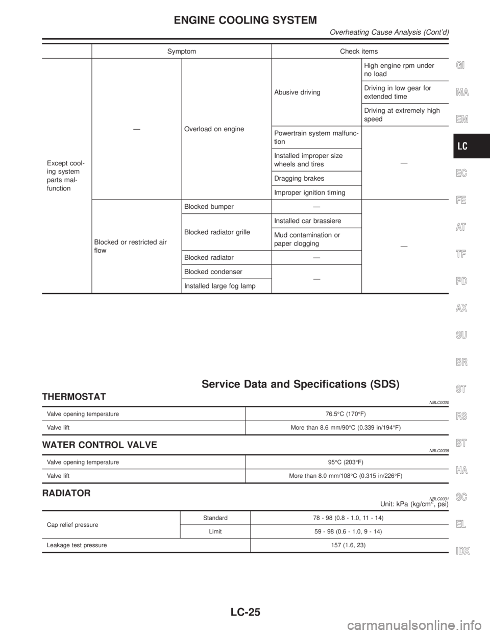
Symptom Check items
Except cool-
ing system
parts mal-
functionÐ Overload on engineAbusive drivingHigh engine rpm under
no load
Driving in low gear for
extended time
Driving at extremely high
speed
Powertrain system malfunc-
tion
Ð Installed improper size
wheels and tires
Dragging brakes
Improper ignition timing
Blocked or restricted air
flowBlocked bumper Ð
Ð Blocked radiator grilleInstalled car brassiere
Mud contamination or
paper clogging
Blocked radiator Ð
Blocked condenser
Ð
Installed large fog lamp
Service Data and Specifications (SDS)
THERMOSTATNBLC0030
Valve opening temperature76.5ÉC (170ÉF)
Valve liftMore than 8.6 mm/90ÉC (0.339 in/194ÉF)
WATER CONTROL VALVENBLC0035
Valve opening temperature95ÉC (203ÉF)
Valve liftMore than 8.0 mm/108ÉC (0.315 in/226ÉF)
RADIATORNBLC0031Unit: kPa (kg/cm2, psi)
Cap relief pressureStandard 78 - 98 (0.8 - 1.0, 11 - 14)
Limit 59 - 98 (0.6 - 1.0,9-14)
Leakage test pressure157 (1.6, 23)
GI
MA
EM
EC
FE
AT
TF
PD
AX
SU
BR
ST
RS
BT
HA
SC
EL
IDX
ENGINE COOLING SYSTEM
Overheating Cause Analysis (Cont'd)
LC-25
Page 2009 of 2395
SMA857C
SMA858C
Changing Engine CoolantNBMA0011WARNING:
To avoid the danger of being scalded, never change the cool-
ant when the engine is hot.
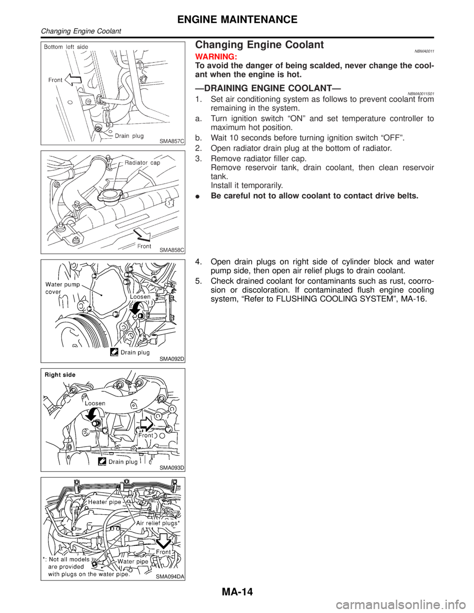
ÐDRAINING ENGINE COOLANTÐNBMA0011S011. Set air conditioning system as follows to prevent coolant from
remaining in the system.
a. Turn ignition switch ªONº and set temperature controller to
maximum hot position.
b. Wait 10 seconds before turning ignition switch ªOFFº.
2. Open radiator drain plug at the bottom of radiator.
3. Remove radiator filler cap.
Remove reservoir tank, drain coolant, then clean reservoir
tank.
Install it temporarily.
IBe careful not to allow coolant to contact drive belts.
SMA092D
SMA093D
SMA094DA
4. Open drain plugs on right side of cylinder block and water
pump side, then open air relief plugs to drain coolant.
5. Check drained coolant for contaminants such as rust, coorro-
sion or discoloration. If contaminated flush engine cooling
system, ªRefer to FLUSHING COOLING SYSTEMº, MA-16.
ENGINE MAINTENANCE
Changing Engine Coolant
MA-14
Page 2011 of 2395
steps 4 through 8 until coolant level no longer drops.
IClean excess coolant from engine.
ÐFLUSHING COOLING SYSTEMÐNBMA0011S031. Open air relief plug.
2. Fill radiator with water until water spills from the air relief holes,
then close air relief plugs. Fill radiator and reservoir tank with
water and reinstall radiator cap.
3. Run engine and warm it up to normal operating temperature.
4. Rev engine two or three times under no-load.
5. Stop engine and wait until it cools down.
6. Drain water.
7. Repeat steps 1 through 6 until clear water begins to drain from
radiator.
SMA803A
Checking Fuel LinesNBMA0012Inspect fuel lines and tank for improper attachment, leaks, cracks,
damage, loose connections, chafing or deterioration.
If necessary, repair or replace faulty parts.
MMA104A
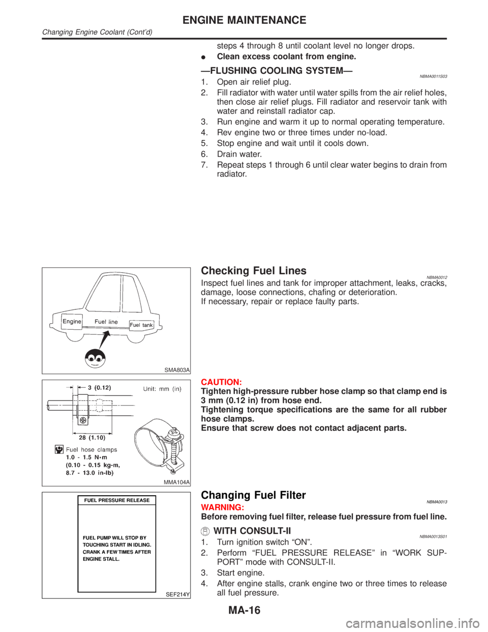
CAUTION:
Tighten high-pressure rubber hose clamp so that clamp end is
3 mm (0.12 in) from hose end.
Tightening torque specifications are the same for all rubber
hose clamps.
Ensure that screw does not contact adjacent parts.
SEF214Y
Changing Fuel FilterNBMA0013WARNING:
Before removing fuel filter, release fuel pressure from fuel line.
WITH CONSULT-IINBMA0013S011. Turn ignition switch ªONº.
2. Perform ªFUEL PRESSURE RELEASEº in ªWORK SUP-
PORTº mode with CONSULT-II.
3. Start engine.
4. After engine stalls, crank engine two or three times to release
all fuel pressure.
ENGINE MAINTENANCE
Changing Engine Coolant (Cont'd)
MA-16
Page 2012 of 2395

5. Turn ignition switch ªOFFº.
SMA861C
6. Loosen fuel hose clamps.
7. Replace fuel filter.
IBe careful not to spill fuel over engine compartment. Place
a shop towel to absorb fuel.
IUse a high-pressure type fuel filter. Do not use a synthetic
resinous fuel filter.
IWhen tightening fuel hose clamps, refer to ªChecking Fuel
Linesº.
SMA869C
WITHOUT CONSULT-IINBMA0013S021. Remove fuel pump fuse located in fuse box.
2. Start engine.
3. After engine stalls, crank it two or three times to release all fuel
pressure.
4. Turn ignition switch ªOFFº and install fuel pump fuse.
SMA861C
5. Loosen fuel hose clamps.
6. Replace fuel filter.
IBe careful not to spill fuel over engine compartment. Place
a shop towel to absorb fuel.
IUse a high-pressure type fuel filter. Do not use a synthetic
resinous fuel filter.
IWhen tightening fuel hose clamps, refer to ªChecking Fuel
Linesº.
SMA095D
Changing Air Cleaner FilterNBMA0014VISCOUS PAPER TYPENBMA0014S01The viscous paper type filter does not need cleaning between
replacement intervals.
GI
EM
LC
EC
FE
AT
TF
PD
AX
SU
BR
ST
RS
BT
HA
SC
EL
IDX
ENGINE MAINTENANCE
Changing Fuel Filter (Cont'd)
MA-17
Page 2014 of 2395

SMA010
2. Clean oil filter mounting surface on cylinder block. Coat rubber
seal of new oil filter with engine oil.
SMA702C
3. Screw in the oil filter until a slight resistance is felt, then tighten
an additional 2/3 turn.
4. Add engine oil.
Refer to MA-18, ªChanging Engine Oilº.
IClean excess oil from engine.
SMA098D
Changing Spark PlugsNBMA00171. Remove engine cover.
2. Remove throttle wires.
3. Remove air duct with air cleaner assembly.
4. Disconnect harness connectors and harness brackets around
ignition coil sides.
5. Remove throttle body. (Only when removing the No. 4 cylinder
spark plug)
6. Disconnect ignition coil harness connectors.
7. Loosen ignition coil fixing bolts and pull out coil from intake
manifold connector.
Ignition coil:
: 8.5 - 10.7 N´m (0.86 - 1.1 kg-m, 75 - 95 in-lb)
SEM294A
8. Check type and gap of new spark plug.
Spark plug type:
Symbol Make
Standard type PLFR5A-11 NGK
Cold type PLFR6A-11 NGK
Hot type PLFR4A-11 NGK
Gap (Nominal): 1.1 mm (0.043 in)
Spark plug:
GI
EM
LC
EC
FE
AT
TF
PD
AX
SU
BR
ST
RS
BT
HA
SC
EL
IDX
ENGINE MAINTENANCE
Changing Oil Filter (Cont'd)
MA-19
Page 2092 of 2395

Precautions
SUPPLEMENTAL RESTRAINT SYSTEM (SRS) ªAIR BAGº AND ªSEAT BELT
PRE-TENSIONERº
NBRS0001The Supplemental Restraint System such as ªAIR BAGº and ªSEAT BELT PRE-TENSIONERº used along with
a seat belt, helps to reduce the risk or severity of injury to the driver and front passenger for certain types of
collision. The SRS composition which is available to INFINITI QX4 is as follows:
IFor a frontal collision
The Supplemental Restraint System consists of driver air bag module (located in the center of the steer-
ing wheel), front passenger air bag module (located on the instrument panel on passenger side), seat belt
pre-tensioners, a diagnosis sensor unit, warning lamp, wiring harness and spiral cable.
IFor a side collision
The Supplemental Restraint System consists of side air bag module (located in the outer side of front seat),
satellite sensor, diagnosis sensor unit (one of components of air bags for a frontal collision), wiring harness,
warning lamp (one of components of air bags for a frontal collision).
WARNING:
ITo avoid rendering the SRS inoperative, which could increase the risk of personal injury or death
in the event of a collision which would result in air bag inflation, all maintenance must be performed
by an authorized INFINITI dealer.
IImproper maintenance, including incorrect removal and installation of the SRS, can lead to per-
sonal injury caused by unintentional activation of the system.
IDo not use electrical test equipment on any circuit related to the SRS unless instructed to in this
Service Manual. Spiral cable and wiring harnesses covered with yellow insulation tape either just
before the harness connectors or for the complete harness are related to the SRS.
PRECAUTION FOR SEAT BELT SERVICENBRS0002CAUTION:
IBefore removing the seat belt pre-tensioner assembly, turn the ignition switch off, disconnect both
battery cables and wait at least 3 minutes.
IDo not use electrical test equipment for seat belt pre-tensioner connector.
IAfter replacing or reinstalling seat belt pre-tensioner assembly, or reconnecting seat belt pre-ten-
sioner connector, check the system function. Refer to ªSRS Operation Checkº (RS-38) for details.
IDo not use disassemble buckle or seat belt assembly.
IReplace anchor bolts if they are deformed or worn out.
INever oil tongue and buckle.
IIf any component of seat belt assembly is questionable, do not repair. Replace the whole seat belt
assembly.
IIf webbing is cut, frayed, or damaged, replace seat belt assembly.
IWhen replacing seat belt assembly, use a genuine seat belt assembly.
After A CollisionNBRS0002S01WARNING:
Inspect all seat belt assemblies including retractors and attaching hardware after any collision.
NISSAN recommends that all seat belt assemblies in use during a collision be replaced unless the
collision was minor and the belts show no damage and continue to operate properly. Failure to do so
could result in serious personal injury in an accident. Seat belt assemblies not in use during a colli-
sion should also be replaced if either damage or improper operation is noted. Seat belt pre-tensioner
should be replaced even if the seat belts are not in use during a frontal collision in which the air bags
are deployed.
Replace any seat belt assembly if:
IThe seat belt was in use at the time of a collision (except for minor collisions and the belts, retractors and
buckles show no damage and continue to operate properly).
IThe seat belt was damaged in an accident. (i.e. torn webbing, bent retractor or guide, etc.)
IThe seat belt attaching point was damaged in an accident. Inspect the seat belt attaching area for dam-
age or distortion and repair as necessary before installing a new seat belt assembly.
IAnchor bolts are deformed or worn out.
IThe seat belt pre-tensioner should be replaced even if the seat belts are not in use during the collision in
which the air bags are deployed.
GI
MA
EM
LC
EC
FE
AT
TF
PD
AX
SU
BR
ST
BT
HA
SC
EL
IDX
SEAT BELTS
Precautions
RS-3
Page 2096 of 2395
Seat Belt Inspection=NBRS0029AFTER A COLLISIONNBRS0029S01WARNING:
Inspect all seat belt assemblies including retractors and attaching hardware after any collision.
NISSAN recommends that all seat belt assemblies in use during a collision be replaced unless the
collision was minor and the belts show no damage and continue to operate properly. Failure to do so
could result in serious personal injury in an accident. Seat belt assemblies not in use during a colli-
sion should also be replaced if either damage or improper operation is noted. Seat belt pre-tensioner
should be replaced even if the seat belts are not in use during a frontal collision in which the air bags
are deployed.
Replace any seat belt assembly if:
IThe seat belt was in use at the time of a collision (except for minor collisions and the belts, retractors and
buckles show no damage and continue to operate properly).
IThe seat belt was damaged in an accident. (i.e. torn webbing, bent retractor or guide, etc.)
IThe seat belt attaching point was damaged in an accident. Inspect the seat belt attaching area for dam-
age or distortion and repair as necessary before installing a new seat belt assembly.
IAnchor bolts are deformed or worn out.
IThe seat belt pre-tensioner should be replaced even if the seat belts are not in use during the collision in
which the air bags are deployed.
PRELIMINARY CHECKSNBRS0029S021. Check the seat belt warning lamp/chime for proper operation as follows:
a. Switch ignition ON. The seat belt warning lamp should illuminate. Also, the seat belt warning chime should
sound for about seven seconds.
b. Fasten driver's seat belt. The seat belt warning lamp should go out and the chime (if sounding) should
stop.
2. If the air bag warning lamp is blinking, conduct self-diagnosis using CONSULT-II, and air bag warning lamp.
Refer to ªSRS Operation Checkº, RS-38.
3. Check that the seat belt retractor, seat belt anchor and buckle bolts are securely attached.
4. Check the shoulder seat belt guide and shoulder belt height adjuster for front seats. Ensure guide swiv-
els freely and that belt lays flat and does not bind in guide. Ensure height adjuster operates properly and
holds securely.
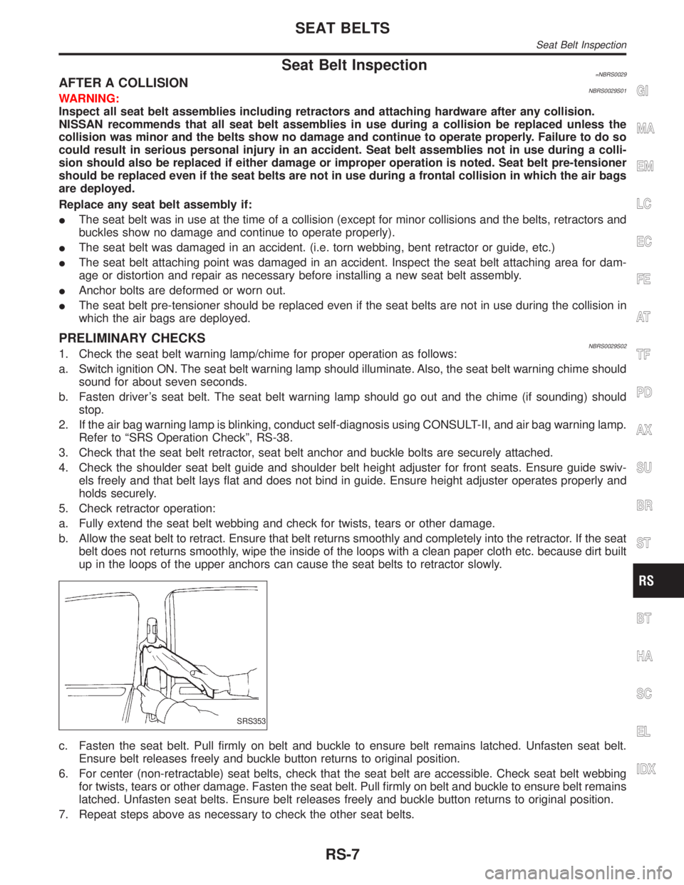
5. Check retractor operation:
a. Fully extend the seat belt webbing and check for twists, tears or other damage.
b. Allow the seat belt to retract. Ensure that belt returns smoothly and completely into the retractor. If the seat
belt does not returns smoothly, wipe the inside of the loops with a clean paper cloth etc. because dirt built
up in the loops of the upper anchors can cause the seat belts to retractor slowly.
SRS353
c. Fasten the seat belt. Pull firmly on belt and buckle to ensure belt remains latched. Unfasten seat belt.
Ensure belt releases freely and buckle button returns to original position.
6. For center (non-retractable) seat belts, check that the seat belt are accessible. Check seat belt webbing
for twists, tears or other damage. Fasten the seat belt. Pull firmly on belt and buckle to ensure belt remains
latched. Unfasten seat belts. Ensure belt releases freely and buckle button returns to original position.
7. Repeat steps above as necessary to check the other seat belts.
GI
MA
EM
LC
EC
FE
AT
TF
PD
AX
SU
BR
ST
BT
HA
SC
EL
IDX
SEAT BELTS
Seat Belt Inspection
RS-7
Page 2099 of 2395
Precautions
SUPPLEMENTAL RESTRAINT SYSTEM (SRS) ªAIR BAGº AND ªSEAT BELT
PRE-TENSIONERº
NBRS0005The Supplemental Restraint System such as ªAIR BAGº and ªSEAT BELT PRE-TENSIONERº used along with
a seat belt, helps to reduce the risk or severity of injury to the driver and front passenger for certain types of
collision. The SRS composition which is available to INFINITI QX4 is as follows:
IFor a frontal collision
The Supplemental Restraint System consists of driver air bag module (located in the center of the steer-
ing wheel), front passenger air bag module (located on the instrument panel on passenger side), seat belt
pre-tensioners, a diagnosis sensor unit, warning lamp, wiring harness and spiral cable.
IFor a side collision
The Supplemental Restraint System consists of side air bag module (located in the outer side of front seat),
satellite sensor, diagnosis sensor unit (one of components of air bags for a frontal collision), wiring harness,
warning lamp (one of components of air bags for a frontal collision).
WARNING:
ITo avoid rendering the SRS inoperative, which could increase the risk of personal injury or death
in the event of a collision which would result in air bag inflation, all maintenance must be performed
by an authorized INFINITI dealer.
IImproper maintenance, including incorrect removal and installation of the SRS, can lead to per-
sonal injury caused by unintentional activation of the system.
IDo not use electrical test equipment on any circuit related to the SRS unless instructed to in this
Service Manual. Spiral cable and wiring harnesses covered with yellow insulation tape either just
before the harness connectors or for the complete harness are related to the SRS.
PRECAUTIONS FOR SRS ªAIR BAGº AND ªSEAT BELT PRE-TENSIONERº SERVICENBRS0006IDo not use electrical test equipment to check SRS circuits unless instructed to in this Service Manual.
IBefore servicing the SRS, turn ignition switch ªOFFº, disconnect both battery cables and wait at least 3
minutes.
For approximately 3 minutes after the cables are removed, it is still possible for the air bag and seat belt
pre-tensioner to deploy. Therefore, do not work on any SRS connectors or wires until at least 3 minutes
have passed.
IDiagnosis sensor unit must always be installed with their arrow marks ªgº pointing towards the front of
the vehicle for proper operation. Also check diagnosis sensor unit for cracks, deformities or rust before
installation and replace as required.
IThe spiral cable must be aligned with the neutral position since its rotations are limited. Do not attempt to
turn steering wheel or column after removal of steering gear.
IHandle air bag module carefully. Always place driver and passenger air bag modules with the pad side
facing upward and side air bag module (built-in type) standing with the stud bolt side setting bottom.
IConduct self-diagnosis to check entire SRS for proper function after replacing any components.
IAfter air bag inflates, the front instrument panel assembly should be replaced if damaged.
WIRING DIAGRAMS AND TROUBLE DIAGNOSISNBRS0007When you read wiring diagrams, refer to the following:
IGI-11, ªHOW TO READ WIRING DIAGRAMSº
IEL-9, ªPOWER SUPPLY ROUTINGº for power distribution circuit
When you perform trouble diagnosis, refer to the following:
IGI-35, ªHOW TO FOLLOW TEST GROUPS IN TROUBLE DIAGNOSESº
IGI-24, ªHOW TO PERFORM EFFICIENT DIAGNOSIS FOR AN ELECTRICAL INCIDENTº
SUPPLEMENTAL RESTRAINT SYSTEM (SRS)
Precautions
RS-10
Page 2101 of 2395

DescriptionNBRS0009
SRS585-F
The air bag deploys if the diagnosis sensor unit activates while the ignition switch is in the ªONº or ªSTARTº
position.
The collision modes for which supplemental restraint systems are activated are different among the SRS sys-
tems. For example, the driver air bag module and passenger air bag module are activated in a frontal colli-
sion but not in a side collision.
SRS configurations which are activated for some collision modes are as follows;
SRS configuration Frontal collision Left side collision Right side collision
Driver air bag moduleqÐÐ
Passenger air bag moduleqÐÐ
Seat belt pre-tensioner (Driver side)qÐÐ
Seat belt pre-tensioner (Passenger side)qÐÐ
Side air bag module (LH) ÐqÐ
Side air bag module (RH) Ð Ðq
SRS444
Seat Belt Pre-tensioner with Load LimiterNBRS0032The seat belt pre-tensioner system with load limiter is installed to
both the driver's seat and the front passenger's seat. It operates
simultaneously with the SRS air bag system in the event of a fron-
tal collision with an impact exceeding a specified level.
When the frontal collision with an impact exceeding a specified
level occurs, seat belt slack resulting from clothing or other factors
is immediately taken up by the pre-tensioner. Vehicle passengers
are securely restrained.
When passengers in a vehicle are thrown forward in a collision and
the restraining force of the seat belt exceeds a specified level, the
SUPPLEMENTAL RESTRAINT SYSTEM (SRS)
Description
RS-12