engine INFINITI QX4 2001 Factory Workshop Manual
[x] Cancel search | Manufacturer: INFINITI, Model Year: 2001, Model line: QX4, Model: INFINITI QX4 2001Pages: 2395, PDF Size: 43.2 MB
Page 93 of 2395

Items Symptom Condition Diagnostic Item Reference Page
Slips/Will Not
EngageRaces extremely
fast or slips in
changing from D
4or D3to D1when
depressing pedal.ON vehicle1. Fluid level AT-59
2. Throttle position sensor (Adjustment) EC-174
3. Line pressure test AT-62
4. Line pressure solenoid valve AT-162
5. Control valve assembly AT-273
OFF vehicle6. Forward clutch AT-320
7. Forward one-way clutch AT-330
8. Low one-way clutch AT-328
Vehicle will not
run in any posi-
tion.ON vehicle1. Fluid level AT-59
2. Manual control linkage adjustment AT-276
3. Line pressure test AT-62
4. Line pressure solenoid valve AT-162
OFF vehicle5. Oil pump AT-297
6. High clutch AT-317
7. Brake band AT-333
8. Low & reverse brake AT-324
9. Torque converter AT-286
10. Parking pawl components AT-337
NOT USEDEngine cannot be
started in P and N
positions.
AT-221ON vehicle1. Ignition switch and starter EL-9, and SC-10
2. Manual control linkage adjustment AT-276
3. Park/neutral position (PNP) switch
adjustmentAT-276
Engine starts in
positions other
than P and N.
AT-221ON vehicle1. Manual control linkage adjustment AT-276
2. Park/neutral position (PNP) switch
adjustmentAT-276
Transmission
noise in P and N
positions.ON vehicle1. Fluid level AT-59
2. Line pressure test AT-62
3. Throttle position sensor (Adjustment) EC-174
4. Vehicle speed sensor´A/T (Revolution
sensor) and vehicle speed sensor´MTRAT- 111 , 1 9 7
5. Engine speed signal AT-116
OFF vehicle6. Oil pump AT-297
7. Torque converter AT-286
Vehicle moves
when changing
into P position or
parking gear does
not disengage
when shifted out
of P position.
AT-222ON vehicle 1. Manual control linkage adjustment AT-276
OFF vehicle 2. Parking pawl components AT-337
TROUBLE DIAGNOSIS Ð GENERAL DESCRIPTION
Symptom Chart (Cont'd)
AT-88
Page 94 of 2395

Items Symptom Condition Diagnostic Item Reference Page
NOT USEDVehicle runs in N
position.
AT-223ON vehicle 1. Manual control linkage adjustment AT-276
OFF vehicle2. Forward clutch AT-320
3. Reverse clutch AT-314
4. Overrun clutch AT-320
Vehicle braked
when shifting into
R position.ON vehicle1. Fluid level AT-59
2. Manual control linkage adjustment AT-276
3. Line pressure test AT-62
4. Line pressure solenoid valve AT-162
5. Control valve assembly AT-273
OFF vehicle6. High clutch AT-317
7. Brake band AT-333
8. Forward clutch AT-320
9. Overrun clutch AT-320
Excessive creep. ON vehicle 1. Engine idling rpm EC-431
Engine stops
when shifting
lever into R, D, 2
and 1.ON vehicle1. Engine idling rpm EC-431
2. Torque converter clutch solenoid valve AT-148
3. Control valve assembly AT-273
OFF vehicle 4. Torque converter AT-286
Vehicle braked by
gear change from
D
1to D2.ON vehicle 1. Fluid level AT-59
OFF vehicle2. Reverse clutch AT-314
3. Low & reverse brake AT-324
4. High clutch AT-317
5. Low one-way clutch AT-328
Vehicle braked by
gear change from
D
2to D3.ON vehicle 1. Fluid level AT-59
OFF vehicle 2. Brake band AT-333
Vehicle braked by
gear change from
D
3to D4.ON vehicle 1. Fluid level AT-59
OFF vehicle2. Overrun clutch AT-320
3. Forward one-way clutch AT-330
4. Reverse clutch AT-314
GI
MA
EM
LC
EC
FE
TF
PD
AX
SU
BR
ST
RS
BT
HA
SC
EL
IDX
TROUBLE DIAGNOSIS Ð GENERAL DESCRIPTION
Symptom Chart (Cont'd)
AT-89
Page 95 of 2395

Items Symptom Condition Diagnostic Item Reference Page
NOT USEDMaximum speed
not attained.
Acceleration poor.ON vehicle1. Fluid level AT-59
2. Park/neutral position (PNP) switch
adjustmentAT-276
3. Shift solenoid valve A AT-168
4. Shift solenoid valve B AT-172
5. Control valve assembly AT-273
OFF vehicle6. Reverse clutch AT-314
7. High clutch AT-317
8. Brake band AT-333
9. Low & reverse brake AT-324
10. Oil pump AT-297
11. Torque converter AT-286
Transmission
noise in D, 2, 1
and R positions.ON vehicle 1. Fluid level AT-59
ON vehicle 2. Torque converter AT-286
Engine brake
does not operate
in ª1º position.
AT-252ON vehicle1. Park/neutral position (PNP) switch
adjustmentAT-276
2. Manual control linkage adjustment AT-276
3. Throttle position sensor (Adjustment) EC-174
4. Vehicle speed sensor´A/T (Revolution
sensor) and vehicle speed sensor´MTRAT- 111 , 1 9 7
5. Shift solenoid valve A AT-168
6. Control valve assembly AT-273
7. Overrun clutch solenoid valve AT-185
OFF vehicle8. Overrun clutch AT-320
9. Low & reverse brake AT-324
Transmission
overheats.ON vehicle1. Fluid level AT-59
2. Engine idling rpm EC-431
3. Throttle position sensor (Adjustment) EC-174
4. Line pressure test AT-62
5. Line pressure solenoid valve AT-162
6. Control valve assembly AT-273
OFF vehicle7. Oil pump AT-297
8. Reverse clutch AT-314
9. High clutch AT-317
10. Brake band AT-333
11. Forward clutch AT-320
12. Overrun clutch AT-320
13. Low & reverse brake AT-324
14. Torque converter AT-286
TROUBLE DIAGNOSIS Ð GENERAL DESCRIPTION
Symptom Chart (Cont'd)
AT-90
Page 96 of 2395

Items Symptom Condition Diagnostic Item Reference Page
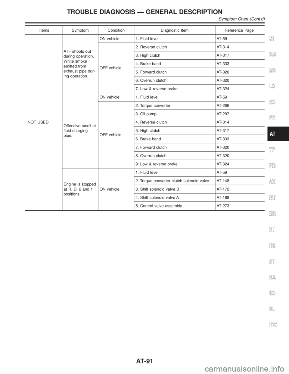
NOT USEDATF shoots out
during operation.
White smoke
emitted from
exhaust pipe dur-
ing operation.ON vehicle 1. Fluid level AT-59
OFF vehicle2. Reverse clutch AT-314
3. High clutch AT-317
4. Brake band AT-333
5. Forward clutch AT-320
6. Overrun clutch AT-320
7. Low & reverse brake AT-324
Offensive smell at
fluid charging
pipe.ON vehicle 1. Fluid level AT-59
OFF vehicle2. Torque converter AT-286
3. Oil pump AT-297
4. Reverse clutch AT-314
5. High clutch AT-317
6. Brake band AT-333
7. Forward clutch AT-320
8. Overrun clutch AT-320
9. Low & reverse brake AT-324
Engine is stopped
at R, D, 2 and 1
positions.ON vehicle1. Fluid level AT-59
2. Torque converter clutch solenoid valve AT-148
3. Shift solenoid valve B AT-172
4. Shift solenoid valve A AT-168
5. Control valve assembly AT-273
GI
MA
EM
LC
EC
FE
TF
PD
AX
SU
BR
ST
RS
BT
HA
SC
EL
IDX
TROUBLE DIAGNOSIS Ð GENERAL DESCRIPTION
Symptom Chart (Cont'd)
AT-91
Page 97 of 2395

AAT475A
TCM Terminals and Reference Value=NBAT0027PREPARATIONNBAT0027S01IMeasure voltage between each terminal and terminal 25 or 48
by following ªTCM INSPECTION TABLEº.
SAT217JB
TCM HARNESS CONNECTOR TERMINAL LAYOUTNBAT0027S02TCM INSPECTION TABLENBAT0027S03(Data are reference values.)
Terminal
No.Wire color Item ConditionJudgement
standard
(Approx.)
1GYLine pressure
solenoid valve
When releasing accelerator pedal after warm-
ing up engine.1.5 - 3.0V
When depressing accelerator pedal fully after
warming up engine.0V
2 BR/YLine pressure
solenoid valve
(with dropping
resistor)When releasing accelerator pedal after warm-
ing up engine.5 - 14V
When depressing accelerator pedal fully after
warming up engine.0V
3 G/ORTorque converter
clutch solenoid
valve
When A/T performs lock-up. 8 - 15V
When A/T does not perform lock- up. 0V
4Ð Ð
ÐÐ
5Ð Ð Ð Ð
6Ð Ð Ð Ð
7Ð Ð Ð Ð
8Ð Ð Ð Ð
9Ð Ð Ð Ð
10 W/R Power sourceWhen turning ignition switch to ªONº.Battery volt-
age
When turning ignition switch to ªOFFº. 0V
TROUBLE DIAGNOSIS Ð GENERAL DESCRIPTION
TCM Terminals and Reference Value
AT-92
Page 98 of 2395

Terminal
No.Wire color Item ConditionJudgement
standard
(Approx.)
11 L/WShift solenoid
valve A
When shift solenoid valve A operates.
(When driving in ªD
1ºorªD4º.)Battery volt-
age
When shift solenoid valve A does not operate.
(When driving in ªD
2ºorªD3º.)0V
12 L/RShift solenoid
valve BWhen shift solenoid valve B operates.
(When driving in ªD
1ºorªD2º.)Battery volt-
age
When shift solenoid valve B does not operate.
(When driving in ªD
3ºorªD4º.)0V
13 GYO/D OFF indica-
tor lamp
When setting overdrive control switch in ªONº
position.Battery volt-
age
When setting overdrive control switch in
ªOFFº position.0V
14 Ð Ð Ð Ð
15 Ð Ð Ð Ð
16 OR/WClosed throttle
position switch
(in throttle posi-
tion switch)When releasing accelerator pedal after warm-
ing up engine.
Refer to ªPreparationº, ªTCM SELF-DIAG-
NOSTIC PROCEDURE (No Tools)º, AT-46.Battery volt-
age
When depressing accelerator pedal after
warming up engine.
Refer to ªPreparationº, ªTCM SELF-DIAG-
NOSTIC PROCEDURE (No Tools)º, AT-46.0V
17 OR/BWide open
throttle position
switch
(in throttle posi-
tion switch)When depressing accelerator pedal more than
half-way after warming up engine.Battery volt-
age
When releasing accelerator pedal after warm-
ing up engine.0V
18 B/YASCD cruise sig-
nal
When ASCD cruise is being performed.
(ªCRUISEº light comes on.)Battery volt-
age
When ASCD cruise is not being performed.
(ªCRUISEº light does not comes on.)0V
19 W/R Power source
Same as No. 10
20 L/BOverrun clutch
solenoid valve
When overrun clutch solenoid valve operates.Battery volt-
age
When overrun clutch solenoid valve does not
operate.0V
21 Ð Ð
ÐÐ
22 GYOverdrive control
switchWhen setting overdrive control switch in ªONº
positionBattery volt-
age
When setting overdrive control switch in
ªOFFº position0V
23 Ð Ð Ð Ð
GI
MA
EM
LC
EC
FE
TF
PD
AX
SU
BR
ST
RS
BT
HA
SC
EL
IDX
TROUBLE DIAGNOSIS Ð GENERAL DESCRIPTION
TCM Terminals and Reference Value (Cont'd)
AT-93
Page 99 of 2395

Terminal
No.Wire color Item ConditionJudgement
standard
(Approx.)
24 W/GASCD OD cut
signal
When ªACCELº set switch on ASCD cruise is
released.5 - 10V
When ªACCELº set switch on ASCD cruise is
applied.Less than 2V
25 B Ground
Ð0V
26 GPNP switch ª1º
position
When setting selector lever to ª1º position.Battery volt-
age
When setting selector lever to other positions. 0V
27 G/WPNP switch ª2º
positionWhen setting selector lever to ª2º position.Battery volt-
age
When setting selector lever to other positions. 0V
28 R/YPower source
(Memory back-up)
or
When turning ignition switch to ªOFFº.Battery volt-
age
When turning ignition switch to ªONº.Battery volt-
age
29 WRevolution sensor
(Measure in AC
range)
When vehicle cruises at 30 km/h (19 MPH).1V or more
Voltage rises
gradually in
response to
vehicle speed.
When vehicle parks. 0V
30*2 W (RX)
ÐÐ
31*2 L (TX) Ð Ð
32 P/BThrottle position
sensor
(Power source)Ignition switch ªONº. 4.5 - 5.5V
Ignition switch ªOFFº. 0V
33*1 G/R LAN Ð Ð
34 LPNP switch ªDº
position
When setting selector lever to ªDº position.Battery volt-
age
When setting selector lever to other positions. 0V
35 YPNP switch ªRº
positionWhen setting selector lever to ªRº position.Battery volt-
age
When setting selector lever to other positions. 0V
36 PPNP switch ªNº or
ªPº positionWhen setting selector lever to ªNº or ªPº posi-
tion.Battery volt-
age
When setting selector lever to other positions. 0V
37 Ð Ð Ð Ð
38 WTurbine revolution
sensor (Measure
in AC range)
When engine is running at 1,000 rpm1.2V
Voltage rises
gradually in
response to
engine speed.
TROUBLE DIAGNOSIS Ð GENERAL DESCRIPTION
TCM Terminals and Reference Value (Cont'd)
AT-94
Page 100 of 2395

Terminal
No.Wire color Item ConditionJudgement
standard
(Approx.)
39 W/BEngine speed
signal
Refer to EC-127, ªECM INSPECTION
TABLEº.Ð
40 W/LVehicle speed
sensor
When moving vehicle at 2 to 3 km/h (1 to 2
MPH) for1m(3ft)ormore.Voltage varies
between less
than 1.0V and
more than
4.5V.
41 PThrottle position
sensor
When depressing accelerator pedal slowly
after warming up engine.
(Voltage rises gradually in response to throttle
position.)Fully-closed
throttle:
0.5V - 0.7V
Fully-open
throttle:
4V
42 BThrottle position
sensor
(Ground)Ð0V
45 G/Y Stop lamp switchWhen depressing brake pedalBattery volt-
age
When releasing brake pedal 0V
46 WTransfer control
unitÐÐ
47 RA/T fluid tempera-
ture sensorWhen ATF temperature is 20ÉC (68ÉF). 1.5V
When ATF temperature is 80ÉC (176ÉF). 0.5V
48 B Ground
Ð0V
*1: These terminals are connected to the ECM.
*2: These terminals are connected to the Data link connector for CONSULT-II.
GI
MA
EM
LC
EC
FE
TF
PD
AX
SU
BR
ST
RS
BT
HA
SC
EL
IDX
TROUBLE DIAGNOSIS Ð GENERAL DESCRIPTION
TCM Terminals and Reference Value (Cont'd)
AT-95
Page 102 of 2395

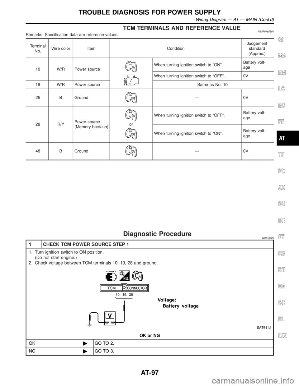
TCM TERMINALS AND REFERENCE VALUENBAT0185S01Remarks: Specification data are reference values.
Terminal
No.Wire color Item ConditionJudgement
standard
(Approx.)
10 W/R Power source
When turning ignition switch to ªONº.Battery volt-
age
When turning ignition switch to ªOFFº. 0V
19 W/R Power source Same as No. 10
25 B Ground
Ð0V
28 R/YPower source
(Memory back-up)
or
When turning ignition switch to ªOFFº.Battery volt-
age
When turning ignition switch to ªONº.Battery volt-
age
48 B Ground
Ð0V
Diagnostic ProcedureNBAT0223
1 CHECK TCM POWER SOURCE STEP 1
1. Turn ignition switch to ON position.
(Do not start engine.)
2. Check voltage between TCM terminals 10, 19, 28 and ground.
SAT611J
OK or NG
OK©GO TO 2.
NG©GO TO 3.
GI
MA
EM
LC
EC
FE
TF
PD
AX
SU
BR
ST
RS
BT
HA
SC
EL
IDX
TROUBLE DIAGNOSIS FOR POWER SUPPLY
Wiring Diagram Ð AT Ð MAIN (Cont'd)
AT-97
Page 105 of 2395

SAT014K
SAT020K
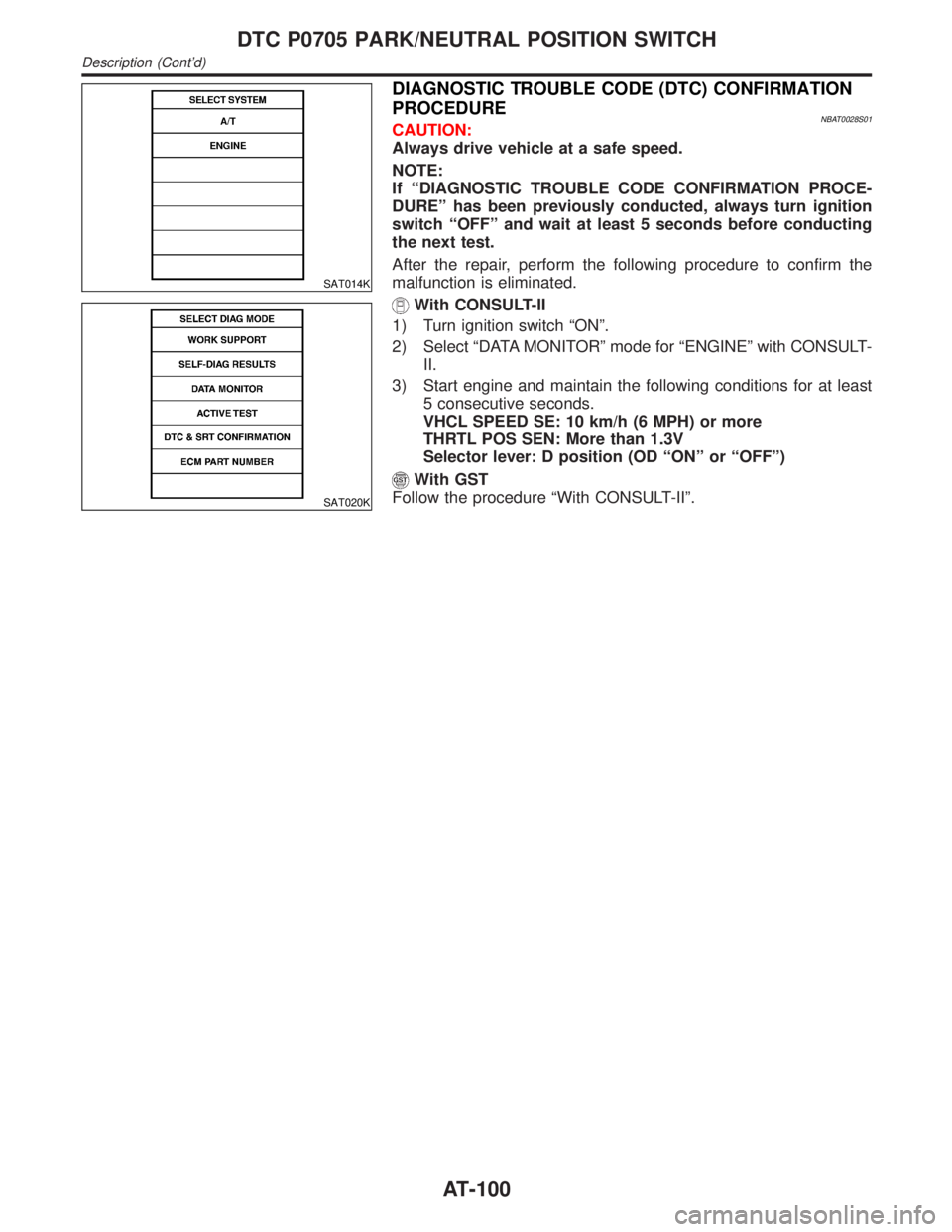
DIAGNOSTIC TROUBLE CODE (DTC) CONFIRMATION
PROCEDURE
NBAT0028S01CAUTION:
Always drive vehicle at a safe speed.
NOTE:
If ªDIAGNOSTIC TROUBLE CODE CONFIRMATION PROCE-
DUREº has been previously conducted, always turn ignition
switch ªOFFº and wait at least 5 seconds before conducting
the next test.
After the repair, perform the following procedure to confirm the
malfunction is eliminated.
With CONSULT-II
1) Turn ignition switch ªONº.
2) Select ªDATA MONITORº mode for ªENGINEº with CONSULT-
II.
3) Start engine and maintain the following conditions for at least
5 consecutive seconds.
VHCL SPEED SE: 10 km/h (6 MPH) or more
THRTL POS SEN: More than 1.3V
Selector lever: D position (OD ªONº or ªOFFº)
With GST
Follow the procedure ªWith CONSULT-IIº.
DTC P0705 PARK/NEUTRAL POSITION SWITCH
Description (Cont'd)
AT-100