101 INFINITI QX4 2001 Factory Service Manual
[x] Cancel search | Manufacturer: INFINITI, Model Year: 2001, Model line: QX4, Model: INFINITI QX4 2001Pages: 2395, PDF Size: 43.2 MB
Page 4 of 2395
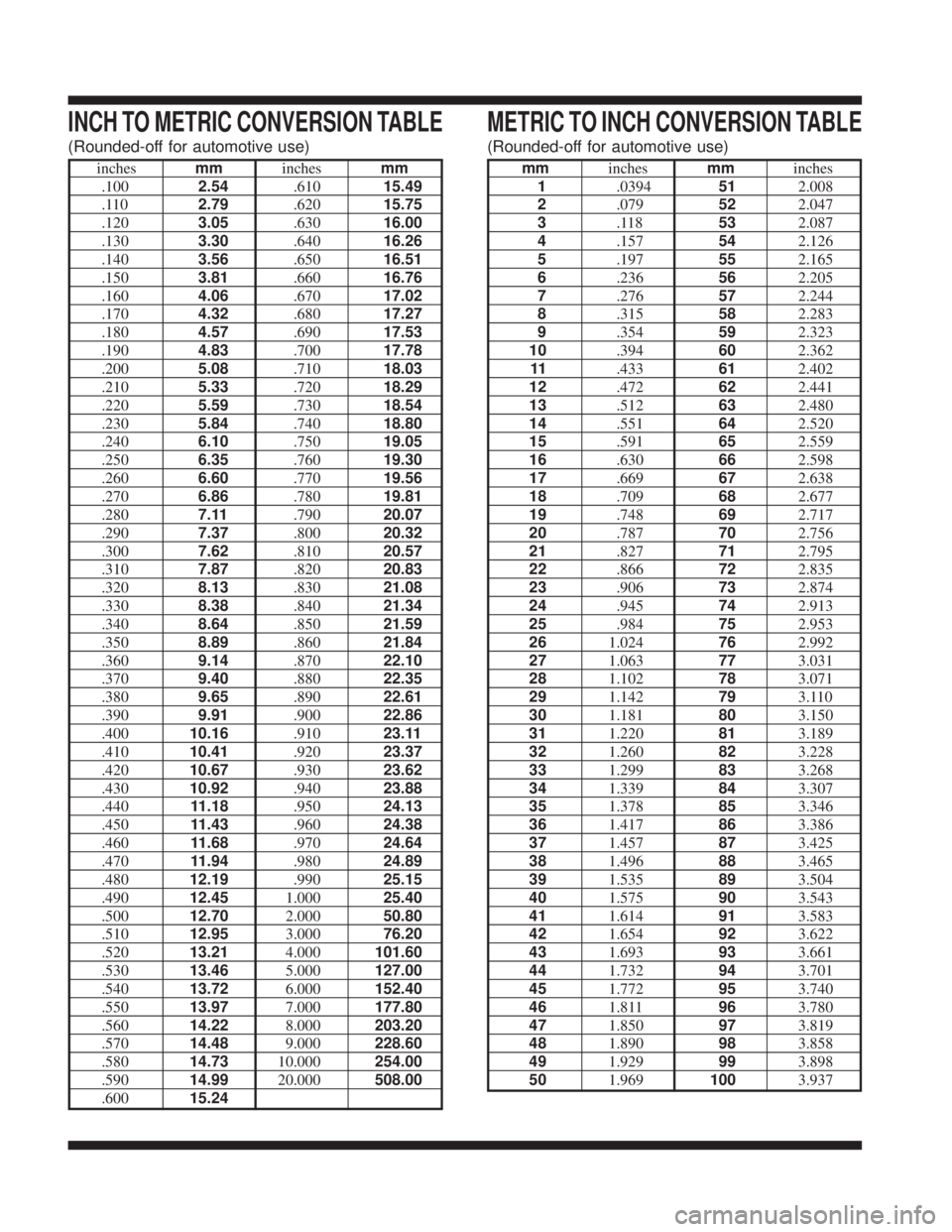
INCH TO METRIC CONVERSION TABLE
(Rounded-off for automotive use)
inchesmminchesmm
.1002.54.61015.49
.1102.79.62015.75
.1203.05.63016.00
.1303.30.64016.26
.1403.56.65016.51
.1503.81.66016.76
.1604.06.67017.02
.1704.32.68017.27
.1804.57.69017.53
.1904.83.70017.78
.2005.08.71018.03
.2105.33.72018.29
.2205.59.73018.54
.2305.84.74018.80
.2406.10.75019.05
.2506.35.76019.30
.2606.60.77019.56
.2706.86.78019.81
.2807.11.79020.07
.2907.37.80020.32
.3007.62.81020.57
.3107.87.82020.83
.3208.13.83021.08
.3308.38.84021.34
.3408.64.85021.59
.3508.89.86021.84
.3609.14.87022.10
.3709.40.88022.35
.3809.65.89022.61
.3909.91.90022.86
.40010.16.91023.11
.41010.41.92023.37
.42010.67.93023.62
.43010.92.94023.88
.44011.18.95024.13
.45011.43.96024.38
.46011.68.97024.64
.47011.94.98024.89
.48012.19.99025.15
.49012.451.00025.40
.50012.702.00050.80
.51012.953.00076.20
.52013.214.000101.60
.53013.465.000127.00
.54013.726.000152.40
.55013.977.000177.80
.56014.228.000203.20
.57014.489.000228.60
.58014.7310.000254.00
.59014.9920.000508.00
.60015.24
METRIC TO INCH CONVERSION TABLE
(Rounded-off for automotive use)
mminchesmminches
1.0394512.008
2.079522.047
3.118532.087
4.157542.126
5.197552.165
6.236562.205
7.276572.244
8.315582.283
9.354592.323
10.394602.362
11.433612.402
12.472622.441
13.512632.480
14.551642.520
15.591652.559
16.630662.598
17.669672.638
18.709682.677
19.748692.717
20.787702.756
21.827712.795
22.866722.835
23.906732.874
24.945742.913
25.984752.953
261.024762.992
271.063773.031
281.102783.071
291.142793.110
301.181803.150
311.220813.189
321.260823.228
331.299833.268
341.339843.307
351.378853.346
361.417863.386
371.457873.425
381.496883.465
391.535893.504
401.575903.543
411.614913.583
421.654923.622
431.693933.661
441.732943.701
451.772953.740
461.811963.780
471.850973.819
481.890983.858
491.929993.898
501.9691003.937
Page 6 of 2395
AUTOMATIC TRANSMISSION
SECTION
AT
CONTENTS
TROUBLE DIAGNOSIS - INDEX....................................4
Alphabetical & P No. Index for DTC ...........................4
PRECAUTIONS...............................................................6
Precautions for Supplemental Restraint System
(SRS)²AIR BAG²and²SEAT BELT
PRE-TENSIONER²......................................................6
Precautions for On Board Diagnostic (OBD)
System of A/T and Engine...........................................6
Precautions ..................................................................6
Service Notice or Precautions .....................................8
Wiring Diagrams and Trouble Diagnosis .....................9
PREPARATION.............................................................10
Special Service Tools ................................................10
OVERALL SYSTEM......................................................12
A/T Electrical Parts Location .....................................12
Circuit Diagram ..........................................................13
Cross-sectional View .................................................14
Hydraulic Control Circuit ............................................15
Shift Mechanism ........................................................16
Control System ..........................................................25
Control Mechanism ....................................................26
Control Valve .............................................................31
ON BOARD DIAGNOSTIC SYSTEM
DESCRIPTION...............................................................33
Introduction ................................................................33
OBD-II Function for A/T System ................................33
One or Two Trip Detection Logic of OBD-II ..............33
OBD-II Diagnostic Trouble Code (DTC) ....................33
Malfunction Indicator Lamp (MIL) ..............................37
CONSULT-II ...............................................................37
Diagnostic Procedure Without CONSULT-II ..............46
TROUBLE DIAGNOSIS - INTRODUCTION..................53
Introduction ................................................................53
Work Flow ..................................................................57
TROUBLE DIAGNOSIS - BASIC INSPECTION...........59
A/T Fluid Check .........................................................59
Stall Test ....................................................................59
Line Pressure Test .....................................................62
Road Test...................................................................63TROUBLE DIAGNOSIS - GENERAL
DESCRIPTION...............................................................81
Symptom Chart ..........................................................81
TCM Terminals and Reference Value........................92
TROUBLE DIAGNOSIS FOR POWER SUPPLY..........96
Wiring Diagram - AT - MAIN ......................................96
Diagnostic Procedure ................................................97
DTC P0705 PARK/NEUTRAL POSITION SWITCH.....99
Description .................................................................99
Wiring Diagram - AT - PNP/SW...............................101
Diagnostic Procedure ..............................................102
Component Inspection .............................................103
DTC P0710 A/T FLUID TEMPERATURE SENSOR
CIRCUIT.......................................................................105
Description ...............................................................105
Wiring Diagram - AT - FTS ......................................107
Diagnostic Procedure ..............................................108
Component Inspection ............................................. 110
DTC P0720 VEHICLE SPEED SENSOR.A/T
(REVOLUTION SENSOR)........................................... 111
Description ............................................................... 111
Wiring Diagram - AT - VSSA/T ................................ 113
Diagnostic Procedure .............................................. 114
Component Inspection ............................................. 115
DTC P0725 ENGINE SPEED SIGNAL....................... 116
Description ............................................................... 116
Wiring Diagram - AT - ENGSS ................................ 117
Diagnostic Procedure .............................................. 118
DTC P0731 IMPROPER SHIFTING TO 1ST GEAR
POSITION....................................................................120
Description ...............................................................120
Wiring Diagram - AT - 1ST ......................................123
Diagnostic Procedure ..............................................124
Component Inspection .............................................125
DTC P0732 IMPROPER SHIFTING TO 2ND GEAR
POSITION....................................................................126
Description ...............................................................126
Wiring Diagram - AT - 2ND......................................129
Diagnostic Procedure ..............................................130
GI
MA
EM
LC
EC
FE
TF
PD
AX
SU
BR
ST
RS
BT
HA
SC
EL
IDX
Page 16 of 2395
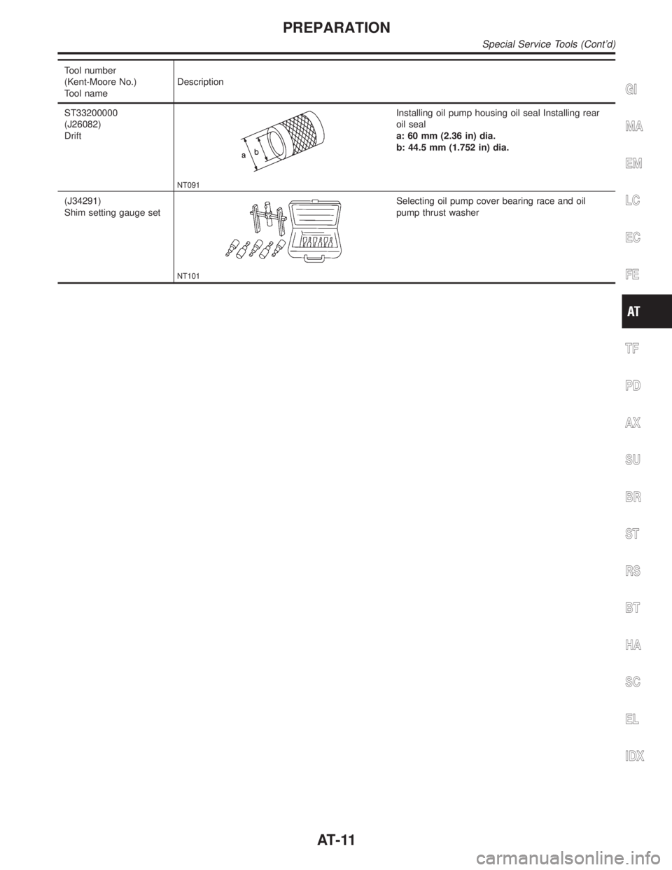
Tool number
(Kent-Moore No.)
Tool nameDescription
ST33200000
(J26082)
Drift
NT091
Installing oil pump housing oil seal Installing rear
oil seal
a: 60 mm (2.36 in) dia.
b: 44.5 mm (1.752 in) dia.
(J34291)
Shim setting gauge set
NT101
Selecting oil pump cover bearing race and oil
pump thrust washer
GI
MA
EM
LC
EC
FE
TF
PD
AX
SU
BR
ST
RS
BT
HA
SC
EL
IDX
PREPARATION
Special Service Tools (Cont'd)
AT-11
Page 29 of 2395

ªRº Position=NBAT0012S0407
Reverse clutch
Low and reverse brakeFront planetary carrier is stationary because of the operation of low and reverse brake.
Input power is transmitted to front sun gear through reverse clutch, which drives front
internal gear in the opposite direction.
Engine brake As there is no one-way clutch in the power transmission line, engine brake can be
obtained when decelerating.
SAT101J
OVERALL SYSTEM
Shift Mechanism (Cont'd)
AT-24
Page 32 of 2395
SAT003J
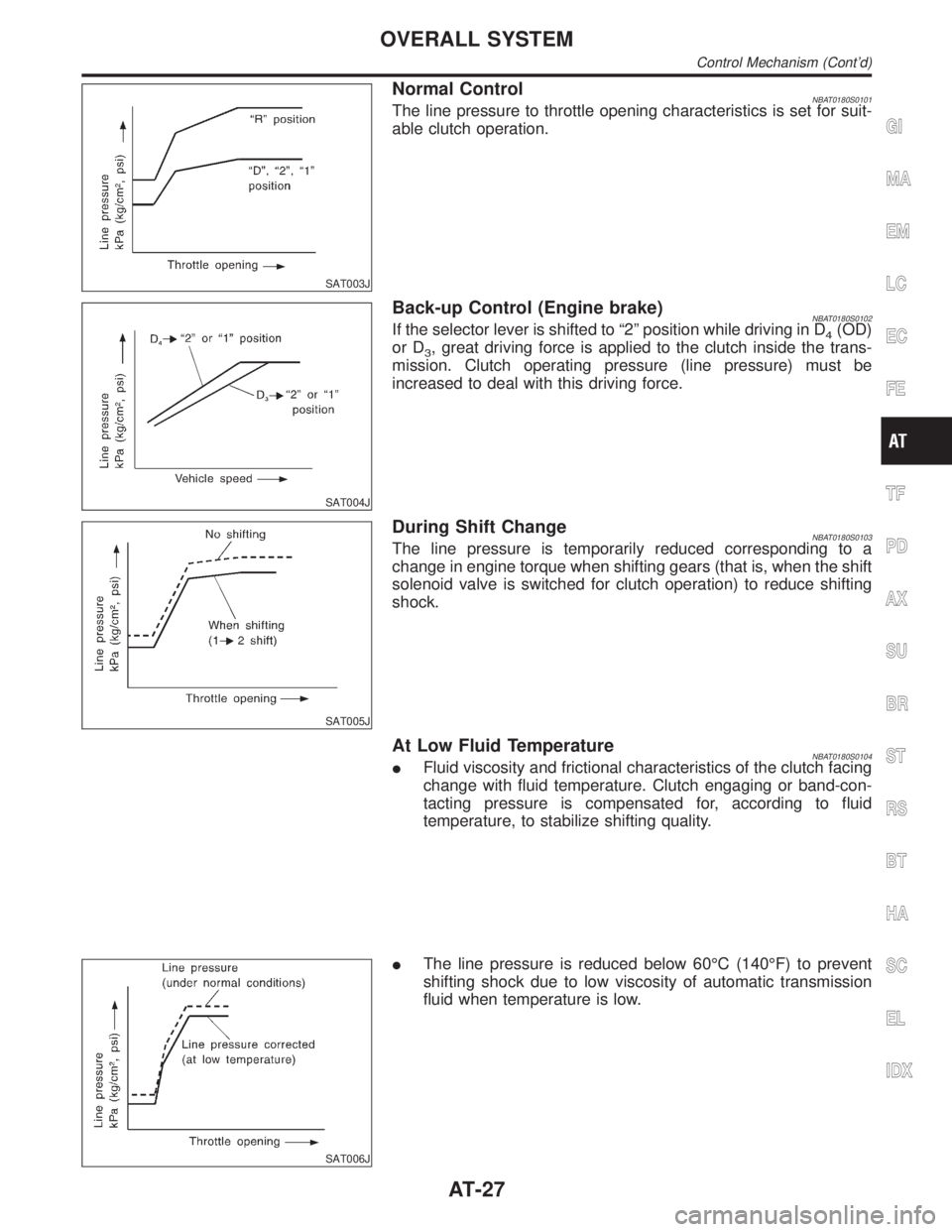
Normal ControlNBAT0180S0101The line pressure to throttle opening characteristics is set for suit-
able clutch operation.
SAT004J
Back-up Control (Engine brake)NBAT0180S0102If the selector lever is shifted to ª2º position while driving in D4(OD)
or D
3, great driving force is applied to the clutch inside the trans-
mission. Clutch operating pressure (line pressure) must be
increased to deal with this driving force.
SAT005J
During Shift ChangeNBAT0180S0103The line pressure is temporarily reduced corresponding to a
change in engine torque when shifting gears (that is, when the shift
solenoid valve is switched for clutch operation) to reduce shifting
shock.
At Low Fluid TemperatureNBAT0180S0104IFluid viscosity and frictional characteristics of the clutch facing
change with fluid temperature. Clutch engaging or band-con-
tacting pressure is compensated for, according to fluid
temperature, to stabilize shifting quality.
SAT006J
IThe line pressure is reduced below 60ÉC (140ÉF) to prevent
shifting shock due to low viscosity of automatic transmission
fluid when temperature is low.
GI
MA
EM
LC
EC
FE
TF
PD
AX
SU
BR
ST
RS
BT
HA
SC
EL
IDX
OVERALL SYSTEM
Control Mechanism (Cont'd)
AT-27
Page 39 of 2395

SAT014K
If the DTC is being detected currently, the time data will be ª0º.
SAT015K
If a 1st trip DTC is stored in the ECM, the time data will be ª1tº.
SAT016K
Freeze Frame Data and 1st Trip Freeze Frame DataNBAT0016S0101The ECM has a memory function, which stores the driving condition such as fuel system status, calculated
load value, engine coolant temperature, short term fuel trim, long term fuel trim, engine speed and vehicle
speed at the moment the ECM detects a malfunction.
Data which are stored in the ECM memory, along with the 1st trip DTC, are called 1st trip freeze frame data,
and the data, stored together with the DTC data, are called freeze frame data and displayed on CONSULT-II
or GST. The 1st trip freeze frame data can only be displayed on the CONSULT-II screen, not on the GST. For
detail, refer to EC-81, ªCONSULT-IIº.
Only one set of freeze frame data (either 1st trip freeze frame data of freeze frame data) can be stored in the
ECM. 1st trip freeze frame data is stored in the ECM memory along with the 1st trip DTC. There is no prior-
ity for 1st trip freeze frame data and it is updated each time a different 1st trip DTC is detected. However, once
freeze frame data (2nd trip detection/MIL on) is stored in the ECM memory, 1st trip freeze frame data is no
longer stored. Remember, only one set of freeze frame data can be stored in the ECM. The ECM has the fol-
lowing priorities to update the data.
ON BOARD DIAGNOSTIC SYSTEM DESCRIPTION
OBD-II Diagnostic Trouble Code (DTC) (Cont'd)
AT-34
Page 59 of 2395

DIAGNOSTIC WORKSHEET=NBAT0019S01Information From CustomerNBAT0019S0101KEY POINTS
WHAT..... Vehicle & A/T model
WHEN..... Date, Frequencies
WHERE..... Road conditions
HOW..... Operating conditions, Symptoms
Customer name MR/MS Model & Year VIN
Trans. model Engine Mileage
Incident Date Manuf. Date In Service Date
FrequencylContinuouslIntermittent ( times a day)
SymptomslVehicle does not move. (lAny positionlParticular position)
lNo up-shift (l1st,2ndl2nd,3rdl3rd,O/D)
lNo down-shift (lO/D,3rdl3rd,2ndl2nd,1st)
lLockup malfunction
lShift point too high or too low.
lShift shock or slip (lN,DlLockuplAny drive position)
lNoise or vibration
lNo kickdown
lNo pattern select
lOthers
()
O/D OFF indicator lamp Blinks for about 8 seconds.
lContinuously litlNot lit
Malfunction indicator lamp (MIL)lContinuously litlNot lit
TROUBLE DIAGNOSIS Ð INTRODUCTION
Introduction (Cont'd)
AT-54
Page 106 of 2395

Wiring Diagram Ð AT Ð PNP/SWNBAT0186
MAT058B
GI
MA
EM
LC
EC
FE
TF
PD
AX
SU
BR
ST
RS
BT
HA
SC
EL
IDX
DTC P0705 PARK/NEUTRAL POSITION SWITCH
Wiring Diagram Ð AT Ð PNP/SW
AT-101
Page 130 of 2395
SAT649I
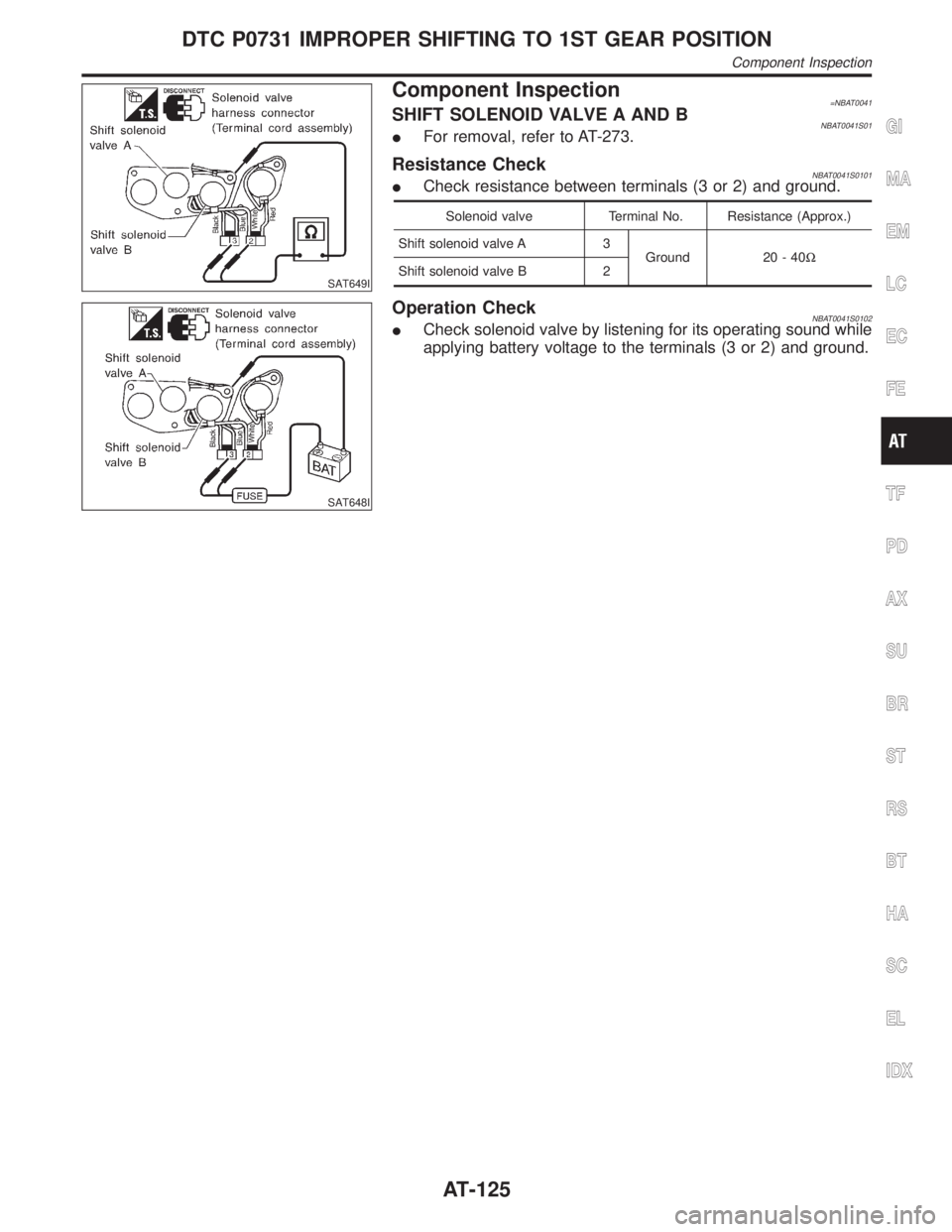
Component Inspection=NBAT0041SHIFT SOLENOID VALVE A AND BNBAT0041S01IFor removal, refer to AT-273.
Resistance CheckNBAT0041S0101ICheck resistance between terminals (3 or 2) and ground.
Solenoid valve Terminal No. Resistance (Approx.)
Shift solenoid valve A 3
Ground 20 - 40W
Shift solenoid valve B 2
SAT648I
Operation CheckNBAT0041S0102ICheck solenoid valve by listening for its operating sound while
applying battery voltage to the terminals (3 or 2) and ground.
GI
MA
EM
LC
EC
FE
TF
PD
AX
SU
BR
ST
RS
BT
HA
SC
EL
IDX
DTC P0731 IMPROPER SHIFTING TO 1ST GEAR POSITION
Component Inspection
AT-125
Page 136 of 2395
SAT651I
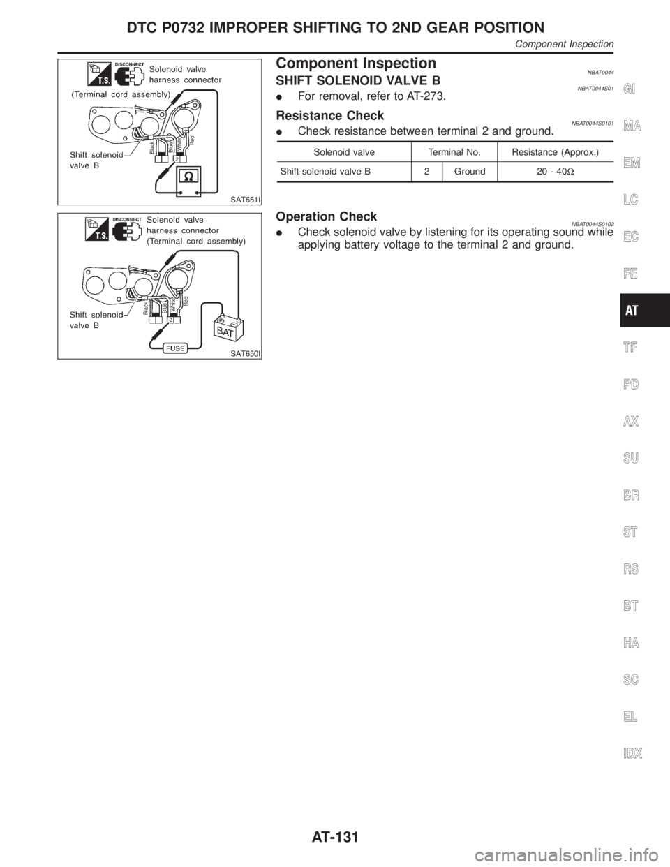
Component InspectionNBAT0044SHIFT SOLENOID VALVE BNBAT0044S01IFor removal, refer to AT-273.
Resistance CheckNBAT0044S0101ICheck resistance between terminal 2 and ground.
Solenoid valve Terminal No. Resistance (Approx.)
Shift solenoid valve B 2 Ground 20 - 40W
SAT650I
Operation CheckNBAT0044S0102ICheck solenoid valve by listening for its operating sound while
applying battery voltage to the terminal 2 and ground.
GI
MA
EM
LC
EC
FE
TF
PD
AX
SU
BR
ST
RS
BT
HA
SC
EL
IDX
DTC P0732 IMPROPER SHIFTING TO 2ND GEAR POSITION
Component Inspection
AT-131