drain bolt INFINITI QX4 2001 Factory Service Manual
[x] Cancel search | Manufacturer: INFINITI, Model Year: 2001, Model line: QX4, Model: INFINITI QX4 2001Pages: 2395, PDF Size: 43.2 MB
Page 278 of 2395

SAT359I
Control Valve Assembly and AccumulatorsNBAT0100REMOVALNBAT0100S011. Remove exhaust front tube.
2. Remove oil pan and gasket and drain ATF.
SAT073BA
3. Remove A/T fluid temperature sensor if necessary.
4. Remove oil strainer.
SAT353B
5. Remove control valve assembly by removing fixing bolts and
disconnecting harness connector.
Bolt length and location
Bolt symbolmm (in)
A 33 (1.30)
B 45 (1.77)
6. Remove solenoids and valves from valve body if necessary.
7. Remove terminal cord assembly if necessary.
SAT074BA
8. Remove accumulatorA, B, CandDby applying compressed
air if necessary.
IHold each piston with rag.
9. Reinstall any part removed.
IAlways use new sealing parts.
GI
MA
EM
LC
EC
FE
TF
PD
AX
SU
BR
ST
RS
BT
HA
SC
EL
IDX
ON-VEHICLE SERVICE
Control Valve Assembly and Accumulators
AT-273
Page 359 of 2395
SAT010B
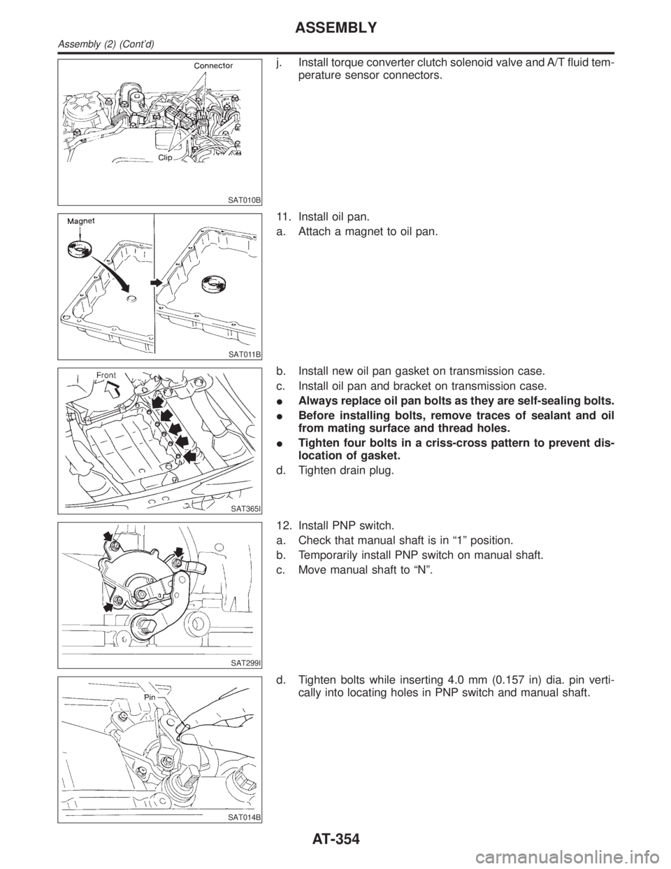
j. Install torque converter clutch solenoid valve and A/T fluid tem-
perature sensor connectors.
SAT011B
11. Install oil pan.
a. Attach a magnet to oil pan.
SAT365I
b. Install new oil pan gasket on transmission case.
c. Install oil pan and bracket on transmission case.
IAlways replace oil pan bolts as they are self-sealing bolts.
IBefore installing bolts, remove traces of sealant and oil
from mating surface and thread holes.
ITighten four bolts in a criss-cross pattern to prevent dis-
location of gasket.
d. Tighten drain plug.
SAT299I
12. Install PNP switch.
a. Check that manual shaft is in ª1º position.
b. Temporarily install PNP switch on manual shaft.
c. Move manual shaft to ªNº.
SAT014B
d. Tighten bolts while inserting 4.0 mm (0.157 in) dia. pin verti-
cally into locating holes in PNP switch and manual shaft.
ASSEMBLY
Assembly (2) (Cont'd)
AT-354
Page 399 of 2395

SBR992
RemovalNBBR0011CAUTION:
IBe careful not to splash brake fluid on painted areas; it
may cause paint damage. If brake fluid is splashed on
painted areas, wash it away with water immediately.
IAll hoses must be free from excessive bending, twisting
and pulling.
1. Connect vinyl tube to air bleeder valve.
2. Drain brake fluid from each air bleeder valve by depressing
brake pedal.
3. Remove flare nut connecting brake tube and hose, then with-
draw lock spring.
4. Cover openings to prevent entrance of dirt whenever discon-
necting brake line.
InspectionNBBR0012Check brake lines (tubes and hoses) for cracks, deterioration or
other damage. Replace any damaged parts.
SBR686C
InstallationNBBR0013CAUTION:
IRefill with new brake fluid ªDOT 3º.
INever reuse drained brake fluid.
1. Tighten all flare nuts and connecting bolts.
Flare nut:
: 15 - 17 N´m (1.5 - 1.8 kg-m, 11 - 13 ft-lb)
Connecting bolt:
: 17 - 19 N´m (1.7 - 2.0 kg-m, 12 - 14 ft-lb)
2. Refill until new brake fluid comes out of each air bleeder valve.
3. Bleed air. Refer to ªBleeding Brake Systemº, BR-8.
BRAKE HYDRAULIC LINE
Removal
BR-10
Page 409 of 2395

SBR116BG
Installation=NBBR0027CAUTION:
IBe careful not to deform or bend brake pipes during instal-
lation of booster.
IReplace clevis pin if damaged.
IRefill with new brake fluid ªDOT 3º.
INever reuse drained brake fluid.
ITake care not to damage brake booster mounting bolt
thread when installing. Due to the narrow angle of
installation, the threads can be damaged by the dash
panel.
1. Before fitting booster, temporarily adjust clevis to dimension
shown.
2. Fit booster, then secure mounting nuts (brake pedal bracket to
brake booster) lightly.
3. Connect brake pedal and booster input rod with clevis pin.
4. Secure mounting nuts.
Specification: 13 - 16 N´m (1.3 - 1.6 kg-m,9-12ft-lb)
5. Install master cylinder. Refer to ªInstallationº in ªMASTER
CYLINDERº, BR-18.
6. Adjust brake pedal height and free play. Refer to ªAdjustmentº
in ªBRAKE PEDAL AND BRACKETº, BR-14.
7. Secure lock nut for clevis.
: 16 - 22 N´m (1.6 - 2.2 kg-m, 12 - 16 ft-lb)
8. Bleed air. Refer to ªBleeding Brake Systemº, BR-8.
BRAKE BOOSTER
Installation
BR-20
Page 414 of 2395

SBR020B
ThicknessNBBR0035S0202Thickness variation (At least 8 positions):
Maximum 0.015 mm (0.0006 in)
If thickness variation exceeds the specification, turn rotor with on-
car brake lathe.
Rotor repair limit:
26.0 mm (1.024 in)
SBR574
AssemblyNBBR00361. Insert piston seal into groove on cylinder body.
2. With piston boot fitted to piston, insert piston boot into groove
on cylinder body and install piston.
3. Properly secure piston boot
SBR387D
InstallationNBBR0037CAUTION:
IRefill with new brake fluid ªDOT 3º.
INever reuse drained brake fluid.
1. Install caliper assembly.
2. Install brake hose to caliper securely.
3. Install all parts and secure all bolts.
4. Bleed air. Refer to ªBleeding Brake Systemº, BR-8.
Brake Burnishing ProcedureNBBR0086When experiencing soft brake pedal feel at very low mileage, or
after replacing the rotor, burnish the brake pad contact surfaces
according to the following procedures.
CAUTION:
Only perform this procedure under safe road and traffic con-
ditions. Use extreme caution.
1. Drive the vehicle on a straight smooth road at 50 km/h (31
MPH).
2. Use medium brake pedal/foot effort to bring the vehicle to a
complete stop from 50 km/h (31 MPH). Adjust brake pedal/foot
pressure such that vehicle stopping time equals 3 to 5 sec-
onds.
3. To cool the brake system, drive the vehicle at 50 km/h (31
MPH) for 1 minute without stopping.
4. Repeat steps 1 to 3 10 times or more to complete the burnish-
ing procedure.
GI
MA
EM
LC
EC
FE
AT
TF
PD
AX
SU
ST
RS
BT
HA
SC
EL
IDX
FRONT DISC BRAKE
Inspection (Cont'd)
BR-25
Page 471 of 2395
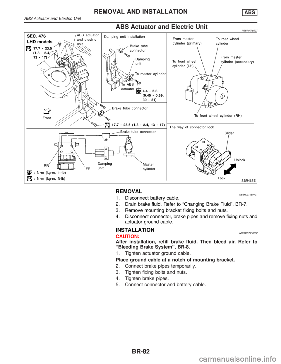
ABS Actuator and Electric UnitNBBR0079S07
SBR468E
REMOVALNBBR0079S07011. Disconnect battery cable.
2. Drain brake fluid. Refer to ªChanging Brake Fluidº, BR-7.
3. Remove mounting bracket fixing bolts and nuts.
4. Disconnect connector, brake pipes and remove fixing nuts and
actuator ground cable.
INSTALLATIONNBBR0079S0702CAUTION:
After installation, refill brake fluid. Then bleed air. Refer to
ªBleeding Brake Systemº, BR-8.
1. Tighten actuator ground cable.
Place ground cable at a notch of mounting bracket.
2. Connect brake pipes temporarily.
3. Tighten fixing bolts and nuts.
4. Tighten brake pipes.
5. Connect connector and battery cable.
REMOVAL AND INSTALLATIONABS
ABS Actuator and Electric Unit
BR-82
Page 1666 of 2395
CAUTION:
IAfter removing timing chain, do not turn crankshaft and
camshaft separately, or valves will strike piston heads.
IWhen installing camshafts, chain tensioners, oil seals, or
other sliding parts, lubricate contacting surfaces with new
engine oil.
IApply new engine oil to bolt threads and seat surfaces
when installing camshaft sprockets and crankshaft pulley.
IBefore disconnecting fuel hose, release fuel pressure.
Refer to EC-39, ªFuel Pressure Releaseº.
IBe careful not to damage sensor edges.
IDo not spill engine coolant on drive belts.
RemovalNBEM00121. Release fuel pressure.
Refer to EC-39, ªFuel Pressure Releaseº.
2. Remove battery.
3. Remove radiator.
Refer to LC-19, ªREMOVAL AND INSTALLATIONº.
4. Drain engine oil.
5. Remove drive belts and idler pulley with brackets.
6. Remove cooling fan with bracket.
7. Remove engine cover.
8. Remove air duct with air cleaner case, collector, blow-by hose,
vacuum hoses, fuel hoses, water hoses, wires, harnesses,
connectors and so on.
9. Remove the air compressor, and tie it down using rope or the
like to keep it from interfering.
10. Remove the power steering oil pump and reservoir tank. Tie
them down using rope or the like to keep them from interfer-
ing.
11. Remove alternator.
12. Remove the following.
IVacuum gallery
IWater bypass pipe
IBrackets
GI
MA
LC
EC
FE
AT
TF
PD
AX
SU
BR
ST
RS
BT
HA
SC
EL
IDX
TIMING CHAIN
Components (Cont'd)
EM-23
Page 1705 of 2395
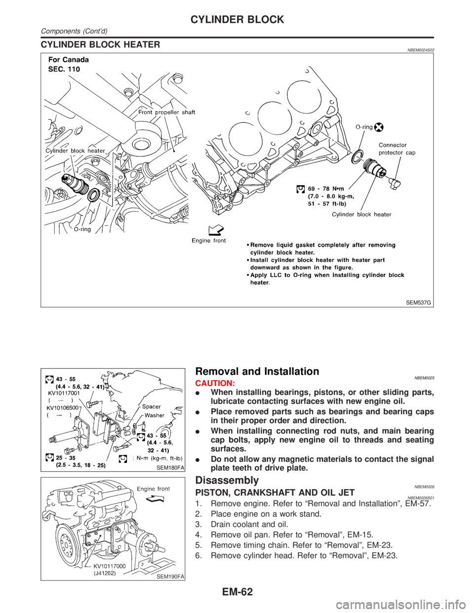
CYLINDER BLOCK HEATERNBEM0024S02
SEM537G
SEM180FA
Removal and InstallationNBEM0025CAUTION:
IWhen installing bearings, pistons, or other sliding parts,
lubricate contacting surfaces with new engine oil.
IPlace removed parts such as bearings and bearing caps
in their proper order and direction.
IWhen installing connecting rod nuts, and main bearing
cap bolts, apply new engine oil to threads and seating
surfaces.
IDo not allow any magnetic materials to contact the signal
plate teeth of drive plate.
SEM190FA
DisassemblyNBEM0026PISTON, CRANKSHAFT AND OIL JETNBEM0026S011. Remove engine. Refer to ªRemoval and Installationº, EM-57.
2. Place engine on a work stand.
3. Drain coolant and oil.
4. Remove oil pan. Refer to ªRemovalº, EM-15.
5. Remove timing chain. Refer to ªRemovalº, EM-23.
6. Remove cylinder head. Refer to ªRemovalº, EM-23.
CYLINDER BLOCK
Components (Cont'd)
EM-62
Page 1986 of 2395

3. Then check if valve closes at 5ÉC (9ÉF) below valve opening
temperature.
Water Control Valve
REMOVAL AND INSTALLATIONNBLC0032
SLC330B
1. Water outlet housing
2. Water control valve
3. Water outlet4. Water hose
5. Cylinder block water outlet
6. Thermal transmitter7. Engine coolant temperature sen-
sor
1. Release fuel pressure.
Refer to EC-39, ªFuel Pressure Releaseº.
2. Remove under cover.
3. Remove suspension member stay.
4. Drain coolant from radiator.
5. Remove engine cover.
6. Remove air duct with air cleaner assembly.
7. Disconnect wires, hoses, harness and so on.
8. Remove upper intake manifold corrector.
9. Remove intake manifold corrector support bolts.
10. Remove lower intake manifold corrector.
11. Disconnect injector harness connectors.
12. Remove injector tube.
13. Remove intake manifold.
14. Remove water outlet housing and water control valve.
GI
MA
EM
EC
FE
AT
TF
PD
AX
SU
BR
ST
RS
BT
HA
SC
EL
IDX
ENGINE COOLING SYSTEM
Thermostat (Cont'd)
LC-17
Page 2200 of 2395
in high-pressure connector. Take care to install the proper
O-ring.
SST616C
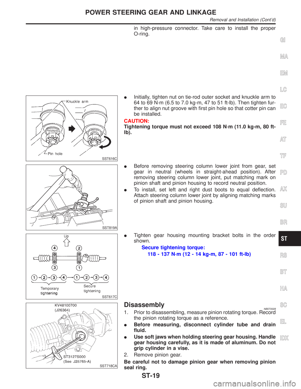
IInitially, tighten nut on tie-rod outer socket and knuckle arm to
64 to 69 N´m (6.5 to 7.0 kg-m, 47 to 51 ft-lb). Then tighten fur-
ther to align nut groove with first pin hole so that cotter pin can
be installed.
CAUTION:
Tightening torque must not exceed 108 N´m (11.0 kg-m, 80 ft-
lb).
SST819A
IBefore removing steering column lower joint from gear, set
gear in neutral (wheels in straight-ahead position). After
removing steering column lower joint, put matching mark on
pinion shaft and pinion housing to record neutral position.
ITo install, set left and right dust boots to equal deflection.
Attach steering column lower joint by aligning matching marks
of pinion shaft and pinion housing.
SST617C
ITighten gear housing mounting bracket bolts in the order
shown.
Secure tightening torque:
118 - 137 N´m (12 - 14 kg-m, 87 - 101 ft-lb)
SST718CA
DisassemblyNBST00281. Prior to disassembling, measure pinion rotating torque. Record
the pinion rotating torque as a reference.
IBefore measuring, disconnect cylinder tube and drain
fluid.
IUse soft jaws when holding steering gear housing. Handle
gear housing carefully, as it is made of aluminum. Do not
grip cylinder in a vise.
2. Remove pinion gear.
Be careful not to damage pinion gear when removing pinion
seal ring.
GI
MA
EM
LC
EC
FE
AT
TF
PD
AX
SU
BR
RS
BT
HA
SC
EL
IDX
POWER STEERING GEAR AND LINKAGE
Removal and Installation (Cont'd)
ST-19