brake rotor INFINITI QX4 2001 Factory User Guide
[x] Cancel search | Manufacturer: INFINITI, Model Year: 2001, Model line: QX4, Model: INFINITI QX4 2001Pages: 2395, PDF Size: 43.2 MB
Page 422 of 2395

System ComponentsNBBR0090
SBR447EB
SBR124B
System DescriptionNBBR0091SENSORNBBR0091S01The sensor unit consists of a gear-shaped sensor rotor and a sen-
sor element. The element contains a bar magnet around which a
coil is wound. The front sensors are installed on the front spindles
and the rear sensors are installed on the rear spindles. As the
wheel rotates, the sensor generates a sine-wave pattern. The fre-
quency and voltage increase(s) as the rotating speed increases.
SBR668E
CONTROL UNIT (BUILT-IN ABS ACTUATOR AND
ELECTRIC UNIT)
NBBR0091S02The control unit computes the wheel rotating speed by the signal
current sent from the sensor. Then it supplies a DC current to the
actuator solenoid valve. It also controls ON-OFF operation of the
valve relay and motor relay. If any electrical malfunction should be
detected in the system, the control unit causes the warning lamp
to light up. In this condition, the ABS will be deactivated by the
control unit, and the vehicle's brake system reverts to normal
operation. (For control unit layout, refer to ABS ACTUATOR AND
ELECTRIC UNIT, BR-33.)
SBR482E
ABS ACTUATOR AND ELECTRIC UNITNBBR0091S03The ABS actuator and electric unit contains:
IAn electric motor and pump
ITwo relays
ISix solenoid valves, each inlet and outlet for
Ð LH front
Ð RH front
Ð Rear
IABS control unit
GI
MA
EM
LC
EC
FE
AT
TF
PD
AX
SU
ST
RS
BT
HA
SC
EL
IDX
DESCRIPTIONABS
System Components
BR-33
Page 440 of 2395

4 CHECK BRAKE BOOSTER OPERATION
Check brake booster for operation and air tightness.
Refer to ªOn-vehicle Serviceº, ªBRAKE BOOSTERº, BR-19.
SBR058C
Is brake booster airtight and functioning properly?
Ye s©GO TO 5.
No©Replace. GO TO 5.
5 CHECK BRAKE PAD AND ROTOR
Check brake pad and rotor.
Refer to (BR-22, BR-24).
SBR059C
Are brake pads and rotors functioning properly?
Ye s©GO TO 6.
No©Replace.
GI
MA
EM
LC
EC
FE
AT
TF
PD
AX
SU
ST
RS
BT
HA
SC
EL
IDX
TROUBLE DIAGNOSIS Ð BASIC INSPECTIONABS
Preliminary Check (Cont'd)
BR-51
Page 458 of 2395

1. ABS Works FrequentlyNBBR0107
1 CHECK BRAKE FLUID PRESSURE
Check brake fluid pressure distribution.
Refer to ªInspectionº, ªLOAD SENSING VALVEº, BR-12.
Is brake fluid pressure distribution normal?
Ye s©GO TO 2.
No©Repair. Then perform Preliminary Check.
Refer to BR-50.
2 CHECK WHEEL SENSOR
1. Check wheel sensor connector for terminal damage or loose connections.
2. Perform wheel sensor mechanical check.
Refer to ª7. CHECK SENSOR ROTORº in ªDIAGNOSTIC PROCEDUREº, ªWheel Sensor or Rotorº, BR-56.
Is wheel sensor mechanism OK?
Ye s©GO TO 3.
No©Repair.
3 CHECK FRONT AXLE
Check front axles for excessive looseness. Refer to AX-4, ªFront Wheel Bearingº.
Is front axle installed properly?
Ye s©Go to ª3. CHECK WARNING LAMP INDICATIONº in ª2. Unexpected Pedal Actionº,
BR-70.
No©Repair.
2. Unexpected Pedal ActionNBBR0108
1 CHECK BRAKE PEDAL STROKE
Check brake pedal stroke.
SBR540A
Is brake pedal stroke excessively large?
Ye s©Perform Preliminary Check. Refer to BR-50.
No©GO TO 2.
GI
MA
EM
LC
EC
FE
AT
TF
PD
AX
SU
ST
RS
BT
HA
SC
EL
IDX
TROUBLE DIAGNOSES FOR SYMPTOMSABS
1. ABS Works Frequently
BR-69
Page 459 of 2395

2 CHECK MECHANICAL BRAKE SYSTEM PERFORMANCE
Disconnect ABS actuator and electric unit connector and check whether brake is effective.
Does brake system function properly when brake pedal is depressed?
Ye s©GO TO 3.
No©Perform Preliminary Check. Refer to BR-50.
3 CHECK WARNING LAMP INDICATION
Ensure warning lamp remains off while driving.
SBR672E
Is warning lamp turned off?
Ye s©GO TO 4.
No©Carry out self-diagnosis. Refer to BR-41, BR-44.
4 CHECK WHEEL SENSOR
1. Check wheel sensor connector for terminal damage or loose connection.
2. Perform wheel sensor mechanical check. Refer to ª7. CHECK SENSOR ROTORº in ªDIAGNOSTIC PROCEDUREº,
ªWheel Sensor or Rotorº, BR-56.
Is wheel sensor mechanism OK?
Ye s©Check ABS actuator and electric unit pin terminals for damage or the connection of ABS
actuator and electric unit harness connector.
Reconnect ABS actuator and electric unit harness connector.
Then retest.
No©Repair.
3. Long Stopping DistanceNBBR0109
1 CHECK MECHANICAL BRAKE SYSTEM PERFORMANCE
Disconnect ABS actuator and electric unit connector and check whether stopping distance is still long.
Does brake system function properly when brake pedal is depressed?
Ye s©Perform Preliminary Check and air bleeding (if necessary).
No©Go to ª3. CHECK WARNING LAMP INDICATIONº in ª2. Unexpected Pedal Actionº,
BR-70.
TROUBLE DIAGNOSES FOR SYMPTOMSABS
2. Unexpected Pedal Action (Cont'd)
BR-70
Page 472 of 2395

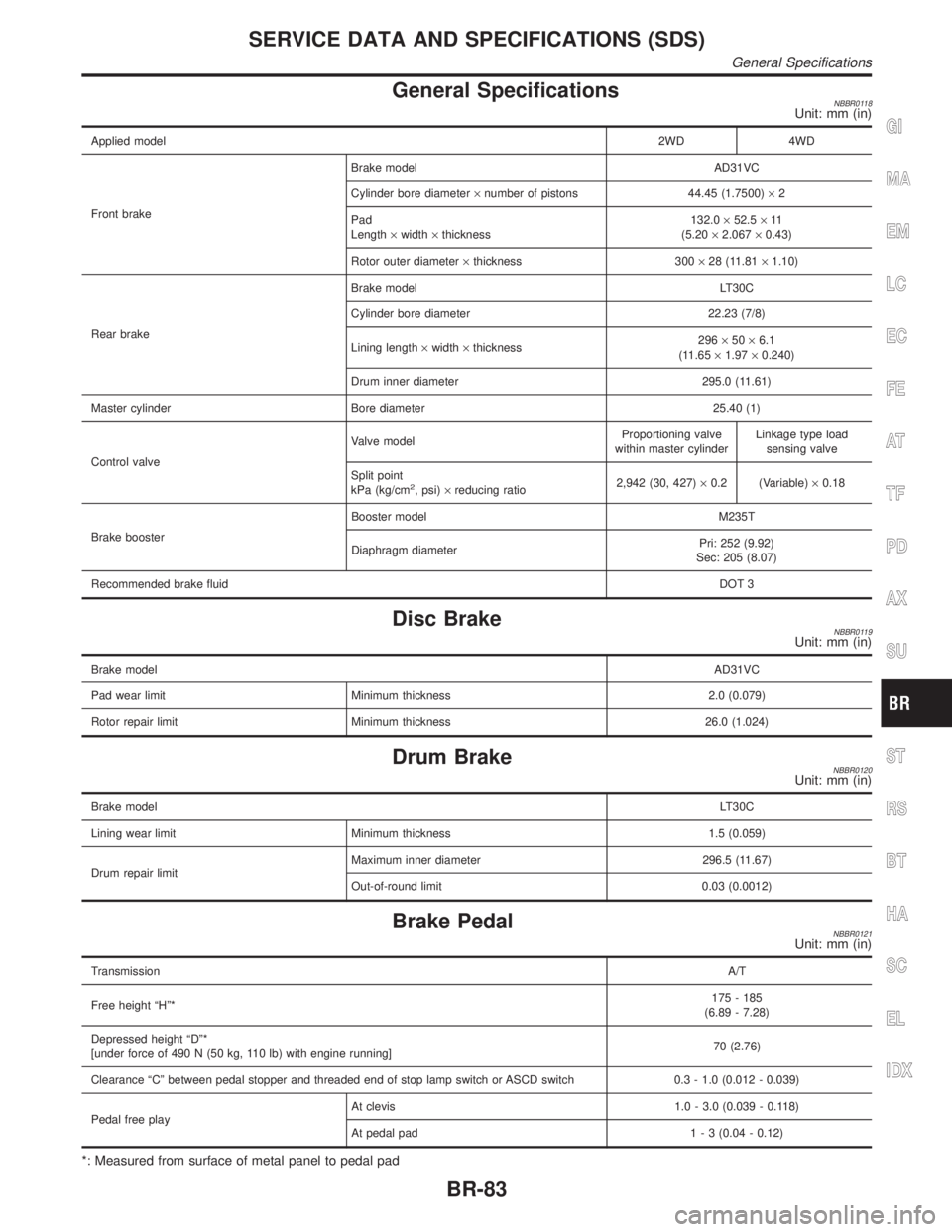
General SpecificationsNBBR0118Unit: mm (in)
Applied model2WD 4WD
Front brakeBrake model AD31VC
Cylinder bore diameter´number of pistons 44.45 (1.7500)´2
Pad
Length´width´thickness132.0´52.5´11
(5.20´2.067´0.43)
Rotor outer diameter´thickness 300´28 (11.81´1.10)
Rear brakeBrake model LT30C
Cylinder bore diameter 22.23 (7/8)
Lining length´width´thickness296´50´6.1
(11.65´1.97´0.240)
Drum inner diameter 295.0 (11.61)
Master cylinder Bore diameter 25.40 (1)
Control valveValve modelProportioning valve
within master cylinderLinkage type load
sensing valve
Split point
kPa (kg/cm
2, psi)´reducing ratio2,942 (30, 427)´0.2 (Variable)´0.18
Brake boosterBooster model M235T
Diaphragm diameterPri: 252 (9.92)
Sec: 205 (8.07)
Recommended brake fluidDOT 3
Disc BrakeNBBR0119Unit: mm (in)
Brake modelAD31VC
Pad wear limit Minimum thickness 2.0 (0.079)
Rotor repair limit Minimum thickness 26.0 (1.024)
Drum BrakeNBBR0120Unit: mm (in)
Brake modelLT30C
Lining wear limit Minimum thickness 1.5 (0.059)
Drum repair limitMaximum inner diameter 296.5 (11.67)
Out-of-round limit 0.03 (0.0012)
Brake PedalNBBR0121Unit: mm (in)
TransmissionA/T
Free height ªHº*175 - 185
(6.89 - 7.28)
Depressed height ªDº*
[under force of 490 N (50 kg, 110 lb) with engine running]70 (2.76)
Clearance ªCº between pedal stopper and threaded end of stop lamp switch or ASCD switch 0.3 - 1.0 (0.012 - 0.039)
Pedal free playAt clevis 1.0 - 3.0 (0.039 - 0.118)
At pedal pad1 - 3 (0.04 - 0.12)
*: Measured from surface of metal panel to pedal pad
GI
MA
EM
LC
EC
FE
AT
TF
PD
AX
SU
ST
RS
BT
HA
SC
EL
IDX
SERVICE DATA AND SPECIFICATIONS (SDS)
General Specifications
BR-83
Page 1745 of 2395

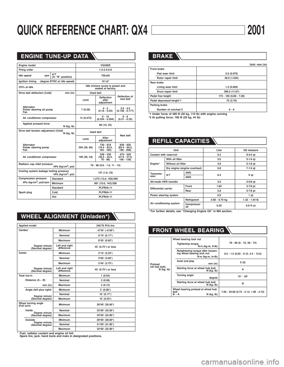
QUICK REFERENCE CHART: QX42001
Engine model VQ35DE
Firing order 1-2-3-4-5-6
Idle speed rpmA/T
(in ªNº position)750 50
Ignition timing (degree BTDC at idle speed) 15É 2É
CO% at idleIdle mixture screw is preset and
sealed at factory.
Drive belt deflection (Cold) mm (in) Used belt
Deflection of
new belt
LimitDeflection
after
adjustment
Alternator
Power steering oil pump
Fan7 (0.28)4-5
(0.16 - 0.20)3.5 - 4.5
(0.138 - 0.177)
Air conditioner compressor 12 (0.472)9-10
(0.354 - 0.394)8-9
(0.31 - 0.35)
Applied pressed force
N (kg, lb)98 (10, 22)
Drive belt tension adjustment (Cold)
N (kg, lb)Used belt
New belt
LimitAfter
adjustment
Alternator
Power steering pump
Fan294 (30, 66)730 - 818
(74.4 - 83.5,
164 - 184)838 - 926
(85.4 - 94.5,
188 - 208)
Air conditioner compressor 196 (20, 44)348 - 436
(35.5 - 44.5,
78 - 98)470 - 559
(47.9 - 57.0,
106 - 126)
Radiator cap relief pressure
kPa (kg/cm
2, psi)78 - 98 (0.8 - 1.0, 11 - 14)
Cooling system leakage testing pressure
kPa (kg/cm
2, psi)157 (1.6, 23)
Compression pressure
kPa (kg/cm
2, psi)/rpmStandard 1,275 (13.0, 185)/300
Minimum 981 (10.0, 142)/300
Spark plugStandard PLFR5A-11
Cold PLFR6A-11
Hot PLFR4A-11
Applied model 245/70 R16 tire
Camber
Degree minute
(Decimal degree)Minimum þ0É35¢(þ0.58É)
Nominal 0É10¢(0.17É)
Maximum 0É55¢(0.92É)
Left and right
difference45¢(0.75É) or less
Caster
Degree minute
(Decimal degree)Minimum 2É15¢(2.25É)
Nominal 3É00¢(3.00É)
Maximum 3É45¢(3.75É)
Left and right
difference45¢(0.75É) or less
Total toe-in Minimum 1 (0.04)
Distance (A þ B)
mm (in)Nominal 2 (0.08)
Maximum 3 (0.12)
Angle (left plus right)
Degree minute
(Decimal degree)Minimum 5¢(0.08É)
Nominal 10¢(0.17É)
Maximum 15¢(0.25É)
Wheel turning angle
(Full turn)Minimum 30É00¢(30.00É)
Inside
Degree minute
(Decimal degree)Nominal 33É00¢(33.00É)
Maximum 34É00¢(34.00É)
Outside
Degree minute
(Decimal degree)Minimum 28É00¢(28.00É)
Nominal 31É00¢(31.00É)
Maximum 32É00¢(32.00É)
* Fuel, radiator coolant and engine oil full.
Spare tire, jack, hand tools and mats in designated positions.
Unit: mm (in)Front brake
Pad wear limit 2.0 (0.079)
Rotor repair limit 26.0 (1.024)
Rear brake
Lining wear limit 1.5 (0.059)
Drum repair limit 296.5 (11.67)
Pedal free height 175 - 185 (6.89 - 7.28)
Pedal depressed height*1 70 (2.76)
Parking brake
Number of notches*2 6 - 8
*1 Under force of 490 N (50 kg, 110 lb) with engine running
*2 At pulling force: 196 N (20 kg, 44 lb)
Unit Liter US measure
Coolant with reservoir 9.2 9-3/4 qt
Engine*With oil filter 5.0 5-1/4 qt
Without oil filter 4.8 5-1/8 qt
Dry engine (engine overhaul) 6.8 7-1/4 qt
Transmis-
sionA/T2WD
8.5 9 qt
4WD
All-mode 4WD transfer 3.0 2-5/8 qt
Differential carrierFront 1.85 3-7/8 pt
Rear 2.8 5-7/8 pt
Power steering system 0.9 1 qt
Air conditioning systemRefrigerant 0.60 - 0.70 kg 1.32 - 1.54 lb
Compressor
oil0.20 6.8 fl oz
* For further details, see ªChanging Engine Oilº in MA section.
Preload
(At hub bolt)
N (kg, lb)Wheel bearing lock nut
78-98(8-10,58-72)
Tightening torque
N×m (kg-m, ft-lb)
Retightening torque after loosen-
ing wheel bearing lock nut
N×m (kg-m, in-lb)0.5 - 1.5 (0.05 - 0.15, 4.3 - 13.0)
Axial end play
mm (in)0 (0)
Starting force at wheel hub bolt
N (kg, lb)A
Turning angle
degree15É - 30É
Starting force at wheel hub bolt
N (kg, lb)B
Wheel bearing preload at wheel hub
bolt
B þ A N (kg, lb)7.06 - 20.99 (0.72 - 2.14, 1.59 - 4.72)
Page 1961 of 2395

A
AAC/V - Wiring diagram ...............................EC-425
ABS - Wiring diagram ....................................BR-37
ABS sensor rotor ........................................AX-6, 19
Absolute pressure sensor ............................EC-158
A/C air flow .....................................................HA-25
A/C component layout ....................................HA-19
A/C compressor clutch removal and
installation .................................................HA-150
A/C compressor precaution..............................HA-6
A/C compressor special service tool..............HA-10
A/C control operation (auto A/C) ....................HA-23
A/C diagnostic work flow (auto A/C) ..............HA-65
A/C HFC134a (R134a) system
precaution .....................................................HA-2
A/C HFC134a (R134a) system service
procedure ..................................................HA-144
A/C HFC134a (R134a) system service
tools.............................................................HA-11
A/C HFC134a system service equip-
ment precaution ............................................HA-7
A/C lubricant (R134a)...................................HA-146
A/C operational check ....................................HA-66
A/C performance chart .................................HA-116
A/C performance test diagnoses ..................HA-114
A/C relay .......................................................HA-110
A/C self-diagnoses (auto A/C)........................HA-44
A/C service data specification ......................HA-160
A/C system description (auto A/C) .................HA-23
A/C trouble diagnoses (auto A/C) ..................HA-27
A/C, A - Wiring diagram ...........................HA-31, 36
Accelerator control system ...............................FE-3
Accelerator wire adjustment .............................FE-3
Actuator lever (Transfer) ...............................TF-120
Air bag ............................................................RS-10
Air bag disposal..............................................RS-22
Air bag precautions ...........................................GI-3
Air bleeding for brake system ..........................BR-8
Air cleaner filter replacement .........................MA-17
Air conditioner cut control ..............................EC-31
Air flow meter - See Mass air flow
sensor .......................................................EC-150
Air mix door control linkage adjustment.........HA-85
Air mix. door motor ................................HA-82, 141
Air spoiler, rear................................................BT-35
All - mode 4WD system ..................................TF-10
Alternator ........................................................SC-28
Ambient sensor ............................................HA-129
Angular tightening application..........................EM-3
Antenna - See Power antenna .....................EL-169
Anti-lock brake system - Wiring
diagram .......................................................BR-37
AP/SEN - Wiring diagram ............................EC-160
ASCD (automatic speed control device) ......EL-221
ASCD - Wiring diagram ................................EL-225
A/T - Wiring diagram - AT - FTS ...................AT-107
A/T - Wiring diagram - AT - MAIN ...................AT-96
A/T - Wiring diagram - AT - PNP/SW............AT-101A/T - Wiring diagram - AT - VSS A/T ............AT-113
A/T control ....................................................EC-440
A/T diagnosis communication line................EC-603
A/T fluid temperature sensor .........................AT-110
A/T self-diagnoses...........................................AT-46
A/T shift lock system .....................................AT-265
A/T shift lock system - Wiring diagram .........AT-266
A/T trouble diagnoses .....................................AT-53
A/T Wiring diagram - AT - ENG SS...............AT-117
A/T Wiring diagram AT - 1ST ........................AT-123
A/T Wiring diagram AT - 2ND .......................AT-129
A/T Wiring diagram AT - 3RD .......................AT-135
A/T Wiring diagram AT - 4TH ........................AT-142
A/T Wiring diagram AT - BA/FTS ..................AT-192
A/T Wiring diagram AT - LPSV .....................AT-164
A/T Wiring diagram AT - NONDTC ...............AT-215
A/T Wiring diagram AT - OVRCSV ...............AT-187
A/T Wiring diagram AT - SSV/A ....................AT-169
A/T Wiring diagram AT - SSV/B ....................AT-173
A/T Wiring diagram AT - TCCSIG .................AT-156
A/T Wiring diagram AT - TCV .......................AT-150
A/T Wiring diagram AT - TPS........................AT-179
A/T Wiring diagram AT - VSSMTR................AT-199
AT/C - Wiring diagram ..................................EC-442
ATP switch.....................................................TF-112
ATP warning lamp .........................................TF-102
Audio .............................................................EL-160
AUDIO - Wiring diagram ...............................EL-162
Audio and A/C control removal and
installation - See Instrument panel .............BT-21
AUT/DP - Wiring diagram .............................EL-191
Auto air conditioner - Wiring diagram ......HA-31, 36
Automatic amplifier...................................HA-40, 72
Automatic drive positioner ............................EL-186
Automatic speed control system - See
ASCD ........................................................EL-221
Automatic transmission fluid
replacement ................................................MA-21
Automatic transmission number ......................GI-43
Auxiliary air control (AAC) valve ..................EC-422
Axle housing (rear) .........................................AX-19
B
Back door ........................................................BT-15
Back door opener - See Back door ................BT-15
Back door trim.................................................BT-34
Back-up lamp ..................................................EL-69
BACK/L - Wiring diagram................................EL-69
Ball joint (front) ...............................................SU-12
Base idle air volume initialiging......................EC-57
Basic inspection ...........................................EC-101
Battery ..............................................................SC-4
Battery/Starting/Charging System
Tester ................................................SC-7, 12, 21
Blower motor ..................................................HA-95
Body alignment ...............................................BT-57
Brake booster .................................................BR-19
Brake control valve (Proportioning
valve)...........................................................BR-11
ALPHABETICAL INDEX
IDX-2
Page 1996 of 2395

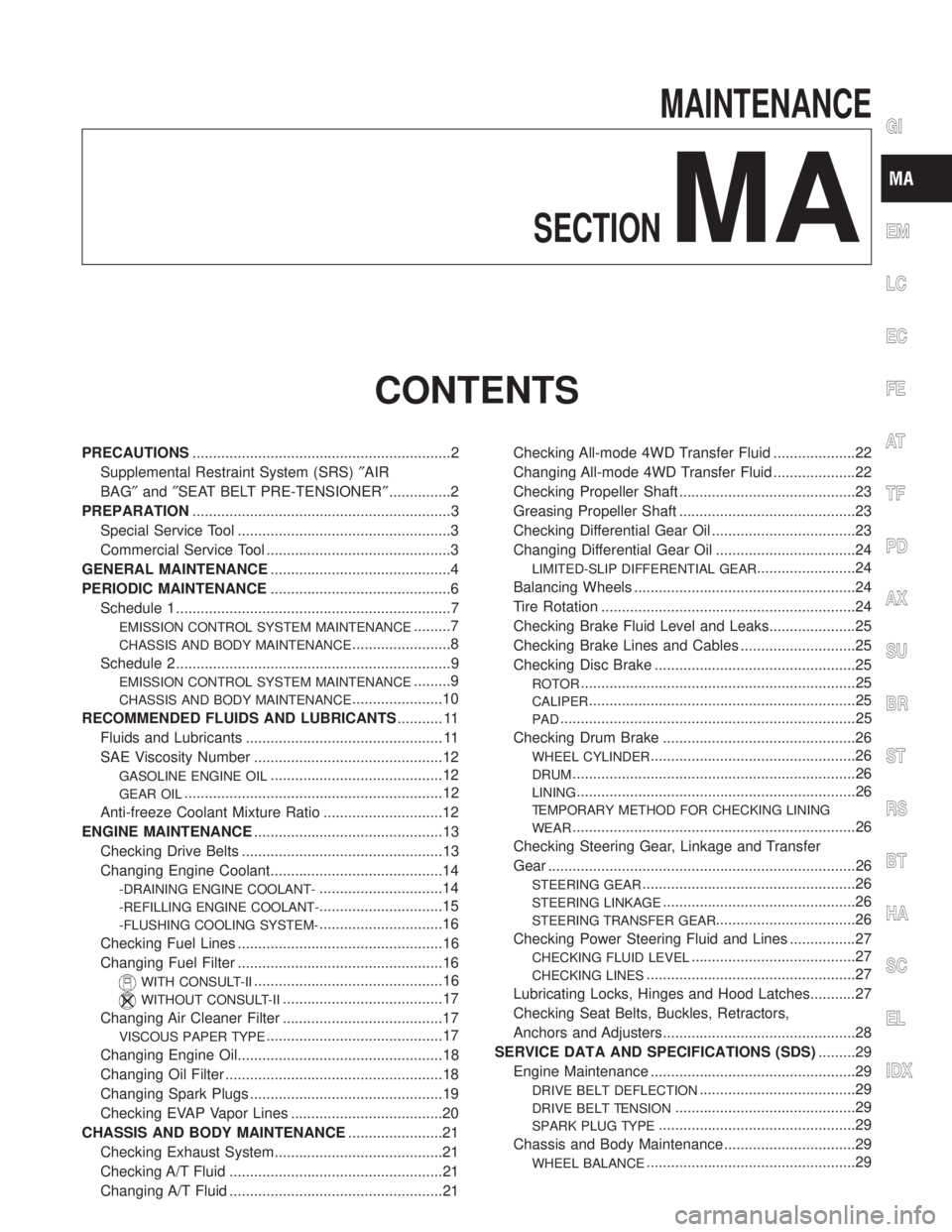
MAINTENANCE
SECTION
MA
CONTENTS
PRECAUTIONS...............................................................2
Supplemental Restraint System (SRS)²AIR
BAG²and²SEAT BELT PRE-TENSIONER²...............2
PREPARATION...............................................................3
Special Service Tool ....................................................3
Commercial Service Tool .............................................3
GENERAL MAINTENANCE............................................4
PERIODIC MAINTENANCE............................................6
Schedule 1 ...................................................................7
EMISSION CONTROL SYSTEM MAINTENANCE.........7
CHASSIS AND BODY MAINTENANCE........................8
Schedule 2 ...................................................................9
EMISSION CONTROL SYSTEM MAINTENANCE.........9
CHASSIS AND BODY MAINTENANCE......................10
RECOMMENDED FLUIDS AND LUBRICANTS........... 11
Fluids and Lubricants ................................................ 11
SAE Viscosity Number ..............................................12
GASOLINE ENGINE OIL..........................................12
GEAR OIL...............................................................12
Anti-freeze Coolant Mixture Ratio .............................12
ENGINE MAINTENANCE..............................................13
Checking Drive Belts .................................................13
Changing Engine Coolant..........................................14
-DRAINING ENGINE COOLANT-..............................14
-REFILLING ENGINE COOLANT-..............................15
-FLUSHING COOLING SYSTEM-..............................16
Checking Fuel Lines ..................................................16
Changing Fuel Filter ..................................................16
WITH CONSULT-II..............................................16
WITHOUT CONSULT-II.......................................17
Changing Air Cleaner Filter .......................................17
VISCOUS PAPER TYPE...........................................17
Changing Engine Oil..................................................18
Changing Oil Filter .....................................................18
Changing Spark Plugs ...............................................19
Checking EVAP Vapor Lines .....................................20
CHASSIS AND BODY MAINTENANCE.......................21
Checking Exhaust System.........................................21
Checking A/T Fluid ....................................................21
Changing A/T Fluid ....................................................21Checking All-mode 4WD Transfer Fluid ....................22
Changing All-mode 4WD Transfer Fluid ....................22
Checking Propeller Shaft ...........................................23
Greasing Propeller Shaft ...........................................23
Checking Differential Gear Oil ...................................23
Changing Differential Gear Oil ..................................24
LIMITED-SLIP DIFFERENTIAL GEAR........................24
Balancing Wheels ......................................................24
Tire Rotation ..............................................................24
Checking Brake Fluid Level and Leaks.....................25
Checking Brake Lines and Cables ............................25
Checking Disc Brake .................................................25
ROTOR...................................................................25
CALIPER.................................................................25
PAD........................................................................25
Checking Drum Brake ...............................................26
WHEEL CYLINDER..................................................26
DRUM.....................................................................26
LINING....................................................................26
TEMPORARY METHOD FOR CHECKING LINING
WEAR
.....................................................................26
Checking Steering Gear, Linkage and Transfer
Gear ...........................................................................26
STEERING GEAR....................................................26
STEERING LINKAGE...............................................26
STEERING TRANSFER GEAR..................................26
Checking Power Steering Fluid and Lines ................27
CHECKING FLUID LEVEL........................................27
CHECKING LINES...................................................27
Lubricating Locks, Hinges and Hood Latches...........27
Checking Seat Belts, Buckles, Retractors,
Anchors and Adjusters...............................................28
SERVICE DATA AND SPECIFICATIONS (SDS).........29
Engine Maintenance ..................................................29
DRIVE BELT DEFLECTION......................................29
DRIVE BELT TENSION............................................29
SPARK PLUG TYPE................................................29
Chassis and Body Maintenance ................................29
WHEEL BALANCE...................................................29
GI
EM
LC
EC
FE
AT
TF
PD
AX
SU
BR
ST
RS
BT
HA
SC
EL
IDX
Page 2001 of 2395

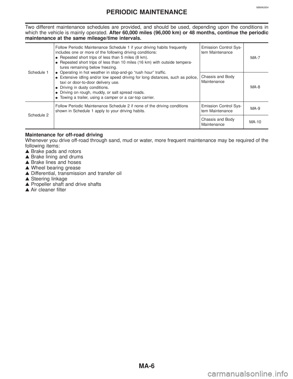
NBMA0004
Two different maintenance schedules are provided, and should be used, depending upon the conditions in
which the vehicle is mainly operated.After 60,000 miles (96,000 km) or 48 months, continue the periodic
maintenance at the same mileage/time intervals.
Schedule 1Follow Periodic Maintenance Schedule 1 if your driving habits frequently
includes one or more of the following driving conditions:
IRepeated short trips of less than 5 miles (8 km).
IRepeated short trips of less than 10 miles (16 km) with outside tempera-
tures remaining below freezing.
IOperating in hot weather in stop-and-go ªrush hourº traffic.
IExtensive idling and/or low speed driving for long distances, such as police,
taxi or door-to-door delivery use.
IDriving in dusty conditions.
IDriving on rough, muddy, or salt spread roads.
ITowing a trailer, using a camper or a car-top carrier.Emission Control Sys-
tem Maintenance
MA-7
Chassis and Body
Maintenance
MA-8
Schedule 2Follow Periodic Maintenance Schedule 2 if none of the driving conditions
shown in Schedule 1 apply to your driving habits.Emission Control Sys-
tem MaintenanceMA-9
Chassis and Body
MaintenanceMA-10
Maintenance for off-road driving
Whenever you drive off-road through sand, mud or water, more frequent maintenance may be required of the
following items:
GBrake pads and rotors
GBrake lining and drums
GBrake lines and hoses
GWheel bearing grease
GDifferential, transmission and transfer oil
GSteering linkage
GPropeller shaft and drive shafts
GAir cleaner filter
PERIODIC MAINTENANCE
MA-6
Page 2003 of 2395

CHASSIS AND BODY MAINTENANCENBMA0004S0102
Abbreviations: R = Replace. I = Inspect. Correct or replace if necessary. L = Lubricate
MAINTENANCE OPERATIONMAINTENANCE INTERVAL
Reference
Section
- Page or
- Content Title Perform at number of miles, kilo-
meters or months, whichever
comes first.Miles x 1,000
(km x 1,000)
Months3.75
(6)
37.5
(12)
611.25
(18)
915
(24)
1218.75
(30)
1522.5
(36)
1826.25
(42)
2130
(48)
2433.75
(54)
2737.5
(60)
3041.25
(66)
3345
(72)
3648.75
(78)
3952.5
(84)
4256.25
(90)
4560
(96)
48
Brake lines & cables I I I I MA-25
Brake pads, rotors, drums & linings I IIIIIIIMA-25, 26
Automatic transmission & all-mode
4WD transfer fluid & differential
gear oil (exc. LSD)NOTE (1) I I I I MA-21, 22, 23
LSD gear oil NOTE (1) I R I R MA-24
Steering gear, linkage & transfer
gear, axle & suspension partsIIIIIIIIMA-26
NOTE (6)
Tire rotation NOTE (2)MA-4
Drive shaft boots (
) IIIIIIIIAX-10, ªDrive
Shaftº
Propeller shaft NOTE (3) L LLLLLLLMA-23
Front wheel bearing grease (4x2) I I
Front wheel bearing
grease (
)NOTE (4) I R I RAX-4, ªFront
Wheel Bearingº
Exhaust system I IIIIIIIMA-21
Supplemental air bag systems NOTE (5)RS-14, ªMainte-
nance Itemsº
Ventilation air filter I RIRIRIRHA-159, ªVentila-
tion Air Filterº
ASCD vacuum hoses I I I IEL-237, ªASCD
ACTUATOR/
PUMP CHECKº
NOTE:
(1) If towing a trailer, using a camper or a car-top carrier, or driving on rough or muddy roads, change (not just inspect) fluid (A/T, all mode 4WD transfer)/differential gear oil (exc.
LSD) at every 30,000 miles (48,000 km) or 24 months, and change LSD gear oil every 15,000 miles (24,000 km) or 12 months.
(2) Refer to ªTire rotationº under the ªGENERAL MAINTENANCEº heading earlier in this section.
(3) The propeller shaft should be re-greased after being immersed in water.
(4) If operating frequently in water, replace grease every 3,750 miles (6,000 km) or 3 months.
(5) Inspect the air bag system 10 years after the date of manufacture noted on the FMVSS certification label.
(6) Refer to SU-5, ªFront Suspension Partsº and SU-16, ªRear Suspension Partsº, AX-3, ªFront Axle Partsº and AX-18, ªRear Axle Partsº.
PERIODIC MAINTENANCE
Schedule 1 (Cont'd)
MA-8