parking brake INFINITI QX4 2001 Factory Service Manual
[x] Cancel search | Manufacturer: INFINITI, Model Year: 2001, Model line: QX4, Model: INFINITI QX4 2001Pages: 2395, PDF Size: 43.2 MB
Page 8 of 2395
19. A/T Does Not Shift: 22-> 11, When Selector
Lever²2²->²1²Position .........................................255
20. Vehicle Does Not Decelerate By Engine
Brake........................................................................256
21. TCM Self-diagnosis Does Not Activate (PNP,
Overdrive Control and Throttle Position Switches
Circuit Checks) ........................................................257
A/T SHIFT LOCK SYSTEM.........................................265
Description ...............................................................265
Wiring Diagram - SHIFT -........................................266
Diagnostic Procedure ..............................................267
KEY INTERLOCK CABLE..........................................271
Components.............................................................271
Removal ...................................................................271
Installation ................................................................272
ON-VEHICLE SERVICE..............................................273
Control Valve Assembly and Accumulators .............273
Revolution Sensor Replacement .............................274
Turbine Revolution Sensor Replacement................274
Rear Oil Seal Replacement .....................................274
Rear Oil Seal and Companion Flange Oil Seal
Replacement ............................................................275
Parking Components Inspection..............................275
Park/Neutral Position Switch Adjustment ................276
Manual Control Linkage Adjustment........................276
REMOVAL AND INSTALLATION...............................277
Removal ...................................................................277
Installation ................................................................278
OVERHAUL.................................................................281
Components.............................................................281
Oil Channel ..............................................................284
Locations of Needle Bearings, Thrust Washers
and Snap Rings .......................................................285
DISASSEMBLY............................................................286
REPAIR FOR COMPONENT PARTS.........................297Oil Pump ..................................................................297
Control Valve Assembly ...........................................301
Control Valve Upper Body .......................................307
Control Valve Lower Body .......................................312
Reverse Clutch ........................................................314
High Clutch ..............................................................317
Forward and Overrun Clutches ...............................320
Low & Reverse Brake..............................................324
Forward Clutch Drum Assembly ..............................328
Rear Internal Gear and Forward Clutch Hub ..........330
Band Servo Piston Assembly ..................................333
Parking Pawl Components ......................................337
ASSEMBLY..................................................................339
Assembly (1) ............................................................339
Adjustment ...............................................................347
Assembly (2) ............................................................349
SERVICE DATA AND SPECIFICATIONS (SDS).......356
General Specifications .............................................356
Shift Schedule..........................................................356
Stall Revolution ........................................................356
Line Pressure...........................................................356
Return Springs .........................................................357
Accumulator O-ring ..................................................358
Clutches and Brakes ...............................................358
Oil Pump and Low One-way Clutch ........................360
Total End Play..........................................................360
Reverse Clutch Drum End Play ..............................361
Removal and Installation .........................................361
Shift Solenoid Valves ...............................................361
Solenoid Valves .......................................................361
A/T Fluid Temperature Sensor.................................361
Turbine Revolution Sensor ......................................361
Revolution Sensor ...................................................362
Dropping Resistor ....................................................362GI
MA
EM
LC
EC
FE
TF
PD
AX
SU
BR
ST
RS
BT
HA
SC
EL
IDX
CONTENTS(Cont'd)
AT-3
Page 21 of 2395
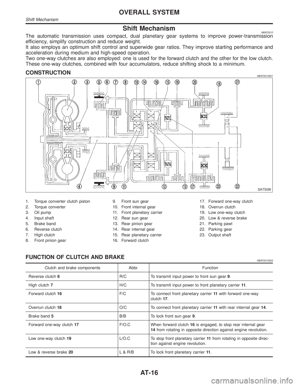
Shift MechanismNBAT0012The automatic transmission uses compact, dual planetary gear systems to improve power-transmission
efficiency, simplify construction and reduce weight.
It also employs an optimum shift control and superwide gear ratios. They improve starting performance and
acceleration during medium and high-speed operation.
Two one-way clutches are also employed: one is used for the forward clutch and the other for the low clutch.
These one-way clutches, combined with four accumulators, reduce shifting shock to a minimum.
CONSTRUCTIONNBAT0012S01
SAT509I
1. Torque converter clutch piston
2. Torque converter
3. Oil pump
4. Input shaft
5. Brake band
6. Reverse clutch
7. High clutch
8. Front pinion gear9. Front sun gear
10. Front internal gear
11. Front planetary carrier
12. Rear sun gear
13. Rear pinion gear
14. Rear internal gear
15. Rear planetary carrier
16. Forward clutch17. Forward one-way clutch
18. Overrun clutch
19. Low one-way clutch
20. Low & reverse brake
21. Parking pawl
22. Parking gear
23. Output shaft
FUNCTION OF CLUTCH AND BRAKENBAT0012S02
Clutch and brake components Abbr. Function
Reverse clutch6R/C To transmit input power to front sun gear9.
High clutch7H/C To transmit input power to front planetary carrier11.
Forward clutch16F/C To connect front planetary carrier11with forward one-way
clutch17.
Overrun clutch18O/C To connect front planetary carrier11with rear internal gear14.
Brake band5B/B To lock front sun gear9.
Forward one-way clutch17F/O.C When forward clutch16is engaged, to stop rear internal gear
14from rotating in opposite direction against engine revolution.
Low one-way clutch19L/O.C To stop front planetary carrier11from rotating in opposite direc-
tion against engine revolution.
Low & reverse brake20L & R/B To lock front planetary carrier11.
OVERALL SYSTEM
Shift Mechanism
AT-16
Page 64 of 2395
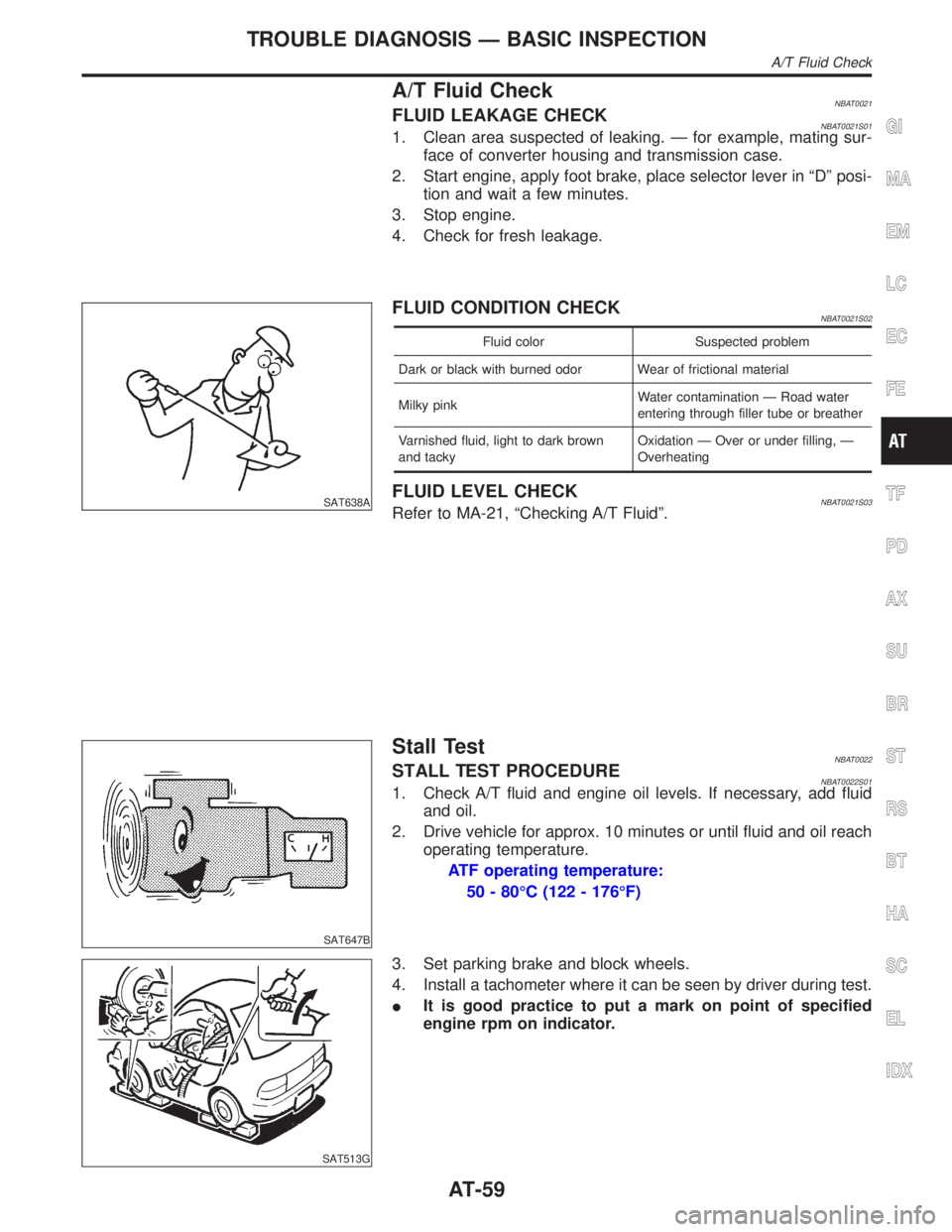
A/T Fluid CheckNBAT0021FLUID LEAKAGE CHECKNBAT0021S011. Clean area suspected of leaking. Ð for example, mating sur-
face of converter housing and transmission case.
2. Start engine, apply foot brake, place selector lever in ªDº posi-
tion and wait a few minutes.
3. Stop engine.
4. Check for fresh leakage.
SAT638A
FLUID CONDITION CHECKNBAT0021S02
Fluid color Suspected problem
Dark or black with burned odor Wear of frictional material
Milky pinkWater contamination Ð Road water
entering through filler tube or breather
Varnished fluid, light to dark brown
and tackyOxidation Ð Over or under filling, Ð
Overheating
FLUID LEVEL CHECKNBAT0021S03Refer to MA-21, ªChecking A/T Fluidº.
SAT647B
Stall TestNBAT0022STALL TEST PROCEDURENBAT0022S011. Check A/T fluid and engine oil levels. If necessary, add fluid
and oil.
2. Drive vehicle for approx. 10 minutes or until fluid and oil reach
operating temperature.
ATF operating temperature:
50 - 80ÉC (122 - 176ÉF)
SAT513G
3. Set parking brake and block wheels.
4. Install a tachometer where it can be seen by driver during test.
IIt is good practice to put a mark on point of specified
engine rpm on indicator.
GI
MA
EM
LC
EC
FE
TF
PD
AX
SU
BR
ST
RS
BT
HA
SC
EL
IDX
TROUBLE DIAGNOSIS Ð BASIC INSPECTION
A/T Fluid Check
AT-59
Page 67 of 2395

SAT209GA
Line Pressure TestNBAT0023ILocation of line pressure test ports.
IAlways replace line pressure plugs as they are self-seal-
ing bolts.
SAT647B
LINE PRESSURE TEST PROCEDURENBAT0023S011. Check A/T fluid and engine oil levels. If necessary, add fluid
and oil.
2. Drive vehicle for approx. 10 minutes or until fluid and oil reach
operating temperature.
ATF operating temperature:
50 - 80ÉC (122 - 176ÉF)
SAT518GB
SAT519GB
3. Install pressure gauge to corresponding line pressure port.
SAT513G
4. Set parking brake and block wheels.
IContinue to depress brake pedal fully while line pressure
test is being performed at stall speed.
TROUBLE DIAGNOSIS Ð BASIC INSPECTION
Line Pressure Test
AT-62
Page 71 of 2395
2. CHECK AT IDLE=NBAT0024S03
1 CHECK ENGINE START
1. Park vehicle on flat surface.
2. Turn ignition switch to ªOFFº position.
3. Move selector lever to ªPº or ªNº position.
4. Turn ignition switch to start position.
5. Is engine started?
YesorNo
Ye s©GO TO 2.
No©Go to ª2. Engine Cannot Be Started In ªPº and ªNº Positionº, AT-221.
2 CHECK ENGINE START
1. Turn ignition switch to ªOFFº position.
2. Move selector lever to ªDº, ª1º, ª2º or ªRº position.
3. Turn ignition switch to start position.
4. Is engine started?
YesorNo
Ye s©Go to ª2. Engine Cannot Be Started In ªPº and ªNº Positionº, AT-221.
No©GO TO 3.
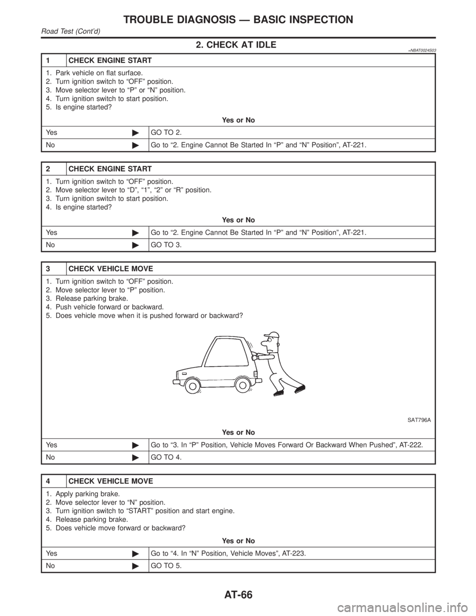
3 CHECK VEHICLE MOVE
1. Turn ignition switch to ªOFFº position.
2. Move selector lever to ªPº position.
3. Release parking brake.
4. Push vehicle forward or backward.
5. Does vehicle move when it is pushed forward or backward?
SAT796A
YesorNo
Ye s©Go to ª3. In ªPº Position, Vehicle Moves Forward Or Backward When Pushedº, AT-222.
No©GO TO 4.
4 CHECK VEHICLE MOVE
1. Apply parking brake.
2. Move selector lever to ªNº position.
3. Turn ignition switch to ªSTARTº position and start engine.
4. Release parking brake.
5. Does vehicle move forward or backward?
YesorNo
Ye s©Go to ª4. In ªNº Position, Vehicle Movesº, AT-223.
No©GO TO 5.
TROUBLE DIAGNOSIS Ð BASIC INSPECTION
Road Test (Cont'd)
AT-66
Page 93 of 2395

Items Symptom Condition Diagnostic Item Reference Page
Slips/Will Not
EngageRaces extremely
fast or slips in
changing from D
4or D3to D1when
depressing pedal.ON vehicle1. Fluid level AT-59
2. Throttle position sensor (Adjustment) EC-174
3. Line pressure test AT-62
4. Line pressure solenoid valve AT-162
5. Control valve assembly AT-273
OFF vehicle6. Forward clutch AT-320
7. Forward one-way clutch AT-330
8. Low one-way clutch AT-328
Vehicle will not
run in any posi-
tion.ON vehicle1. Fluid level AT-59
2. Manual control linkage adjustment AT-276
3. Line pressure test AT-62
4. Line pressure solenoid valve AT-162
OFF vehicle5. Oil pump AT-297
6. High clutch AT-317
7. Brake band AT-333
8. Low & reverse brake AT-324
9. Torque converter AT-286
10. Parking pawl components AT-337
NOT USEDEngine cannot be
started in P and N
positions.
AT-221ON vehicle1. Ignition switch and starter EL-9, and SC-10
2. Manual control linkage adjustment AT-276
3. Park/neutral position (PNP) switch
adjustmentAT-276
Engine starts in
positions other
than P and N.
AT-221ON vehicle1. Manual control linkage adjustment AT-276
2. Park/neutral position (PNP) switch
adjustmentAT-276
Transmission
noise in P and N
positions.ON vehicle1. Fluid level AT-59
2. Line pressure test AT-62
3. Throttle position sensor (Adjustment) EC-174
4. Vehicle speed sensor´A/T (Revolution
sensor) and vehicle speed sensor´MTRAT- 111 , 1 9 7
5. Engine speed signal AT-116
OFF vehicle6. Oil pump AT-297
7. Torque converter AT-286
Vehicle moves
when changing
into P position or
parking gear does
not disengage
when shifted out
of P position.
AT-222ON vehicle 1. Manual control linkage adjustment AT-276
OFF vehicle 2. Parking pawl components AT-337
TROUBLE DIAGNOSIS Ð GENERAL DESCRIPTION
Symptom Chart (Cont'd)
AT-88
Page 270 of 2395

DescriptionNBAT0093IThe mechanical key interlock mechanism also operates as a
shift lock:
With the key switch turned to ªONº, the selector lever cannot
be shifted from ªPº (parking) to any other position unless the
brake pedal is depressed.
With the key removed, the selector lever cannot be shifted
from ªPº to any other position.
The key cannot be removed unless the selector lever is placed
in ªPº.
IThe shift lock and key interlock mechanisms are controlled by
the ON-OFF operation of the shift lock solenoid and by the
operation of the rotator and slider located inside the key
cylinder, respectively.
SAT145K
GI
MA
EM
LC
EC
FE
TF
PD
AX
SU
BR
ST
RS
BT
HA
SC
EL
IDX
A/T SHIFT LOCK SYSTEM
Description
AT-265
Page 284 of 2395
SAT017B
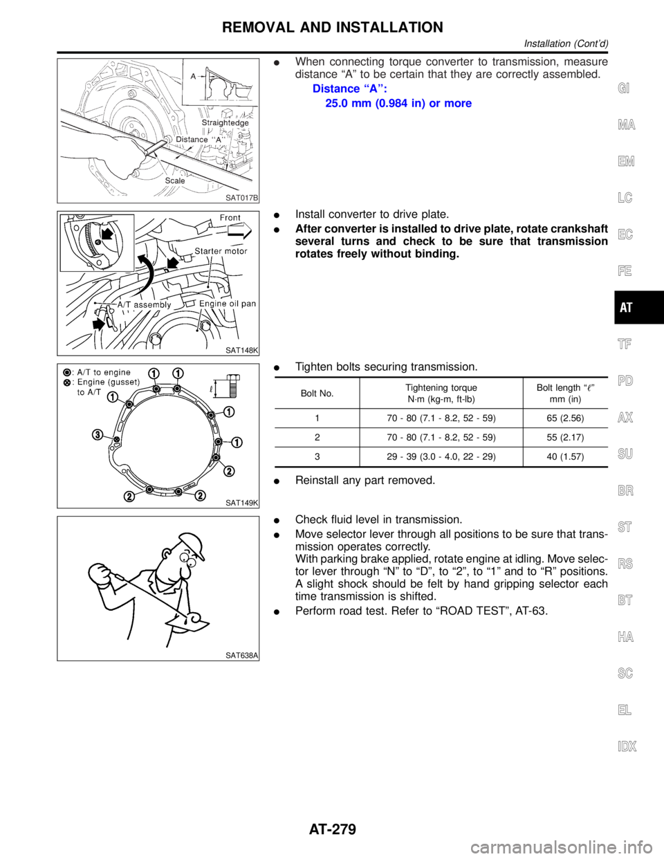
IWhen connecting torque converter to transmission, measure
distance ªAº to be certain that they are correctly assembled.
Distance ªAº:
25.0 mm (0.984 in) or more
SAT148K
IInstall converter to drive plate.
IAfter converter is installed to drive plate, rotate crankshaft
several turns and check to be sure that transmission
rotates freely without binding.
SAT149K
ITighten bolts securing transmission.
Bolt No.Tightening torque
N´m (kg-m, ft-lb)Bolt length ªº
mm (in)
1 70 - 80 (7.1 - 8.2, 52 - 59) 65 (2.56)
2 70 - 80 (7.1 - 8.2, 52 - 59) 55 (2.17)
3 29 - 39 (3.0 - 4.0, 22 - 29) 40 (1.57)
IReinstall any part removed.
SAT638A
ICheck fluid level in transmission.
IMove selector lever through all positions to be sure that trans-
mission operates correctly.
With parking brake applied, rotate engine at idling. Move selec-
tor lever through ªNº to ªDº, to ª2º, to ª1º and to ªRº positions.
A slight shock should be felt by hand gripping selector each
time transmission is shifted.
IPerform road test. Refer to ªROAD TESTº, AT-63.
GI
MA
EM
LC
EC
FE
TF
PD
AX
SU
BR
ST
RS
BT
HA
SC
EL
IDX
REMOVAL AND INSTALLATION
Installation (Cont'd)
AT-279
Page 386 of 2395
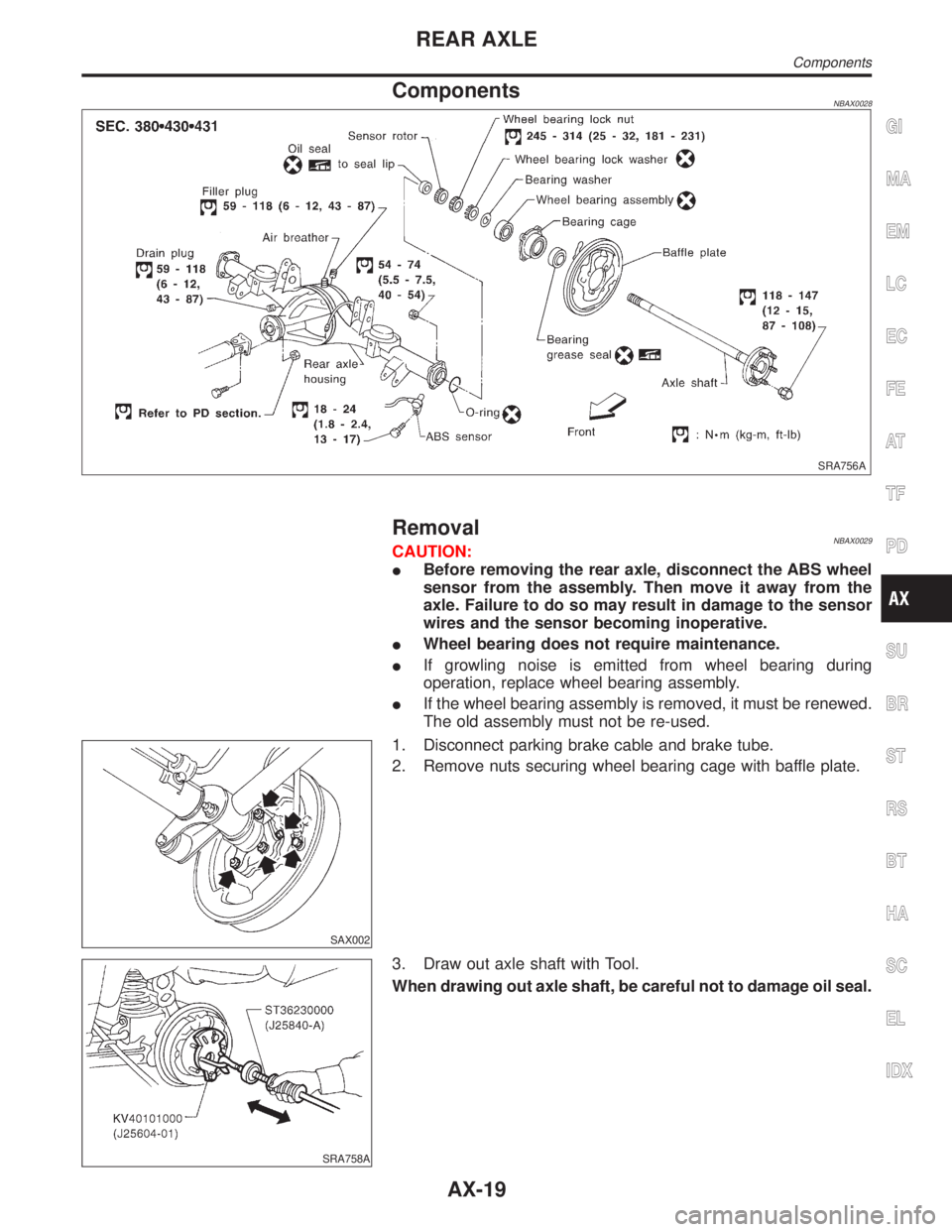
ComponentsNBAX0028
SRA756A
RemovalNBAX0029CAUTION:
IBefore removing the rear axle, disconnect the ABS wheel
sensor from the assembly. Then move it away from the
axle. Failure to do so may result in damage to the sensor
wires and the sensor becoming inoperative.
IWheel bearing does not require maintenance.
IIf growling noise is emitted from wheel bearing during
operation, replace wheel bearing assembly.
IIf the wheel bearing assembly is removed, it must be renewed.
The old assembly must not be re-used.
SAX002
1. Disconnect parking brake cable and brake tube.
2. Remove nuts securing wheel bearing cage with baffle plate.
SRA758A
3. Draw out axle shaft with Tool.
When drawing out axle shaft, be careful not to damage oil seal.
GI
MA
EM
LC
EC
FE
AT
TF
PD
SU
BR
ST
RS
BT
HA
SC
EL
IDX
REAR AXLE
Components
AX-19
Page 390 of 2395

BRAKE SYSTEM
SECTION
BR
CONTENTS
PRECAUTIONS...............................................................3
Supplemental Restraint System (SRS)²AIR
BAG²and²SEAT BELT PRE-TENSIONER²...............3
Precautions for Brake System .....................................3
Wiring Diagrams and Trouble Diagnoses....................4
PREPARATION...............................................................5
Special Service Tools ..................................................5
Commercial Service Tools ...........................................5
NOISE, VIBRATION AND HARSHNESS (NVH)
TROUBLESHOOTING.....................................................6
NVH Troubleshooting Chart.........................................6
ON-VEHICLE SERVICE..................................................7
Checking Brake Fluid Level.........................................7
Checking Brake Line ...................................................7
Changing Brake Fluid ..................................................7
Bleeding Brake System ...............................................8
BRAKE HYDRAULIC LINE.............................................9
Hydraulic Circuit...........................................................9
Removal .....................................................................10
Inspection...................................................................10
Installation ..................................................................10
PROPORTIONING VALVE (2WD)................................ 11
Inspection................................................................... 11
Removal and Installation (Built-in type)..................... 11
LOAD SENSING VALVE (4WD)...................................12
Inspection...................................................................12
Removal and Installation ...........................................12
BRAKE PEDAL AND BRACKET..................................14
Removal and Installation ...........................................14
Inspection...................................................................14
Adjustment .................................................................14
MASTER CYLINDER.....................................................16
Removal .....................................................................16
Disassembly...............................................................16
Inspection...................................................................17
Assembly ...................................................................17
Installation ..................................................................18
BRAKE BOOSTER........................................................19
On-vehicle Service.....................................................19OPERATING CHECK...............................................19
AIRTIGHT CHECK...................................................19
Removal .....................................................................19
Inspection...................................................................19
OUTPUT ROD LENGTH CHECK..............................19
Installation ..................................................................20
VACUUM PIPING...........................................................21
Vacuum Hose ............................................................21
Removal and Installation ...........................................21
Inspection...................................................................21
HOSES AND CONNECTORS...................................21
CHECK VALVE........................................................21
FRONT DISC BRAKE...................................................22
Components...............................................................22
Pad Replacement ......................................................22
Removal .....................................................................23
Disassembly...............................................................24
Inspection...................................................................24
CALIPER.................................................................24
ROTOR...................................................................24
Assembly ...................................................................25
Installation ..................................................................25
Brake Burnishing Procedure......................................25
REAR DRUM BRAKE...................................................26
Components...............................................................26
Removal .....................................................................26
Inspection...................................................................27
WHEEL CYLINDER..................................................27
Wheel Cylinder Overhaul...........................................28
Inspection...................................................................28
DRUM.....................................................................28
LINING....................................................................28
Installation ..................................................................28
PARKING BRAKE CONTROL......................................30
Components...............................................................30
Removal and Installation ...........................................30
Inspection...................................................................30
Adjustment .................................................................31
GI
MA
EM
LC
EC
FE
AT
TF
PD
AX
SU
ST
RS
BT
HA
SC
EL
IDX