starter INFINITI QX4 2001 Factory Service Manual
[x] Cancel search | Manufacturer: INFINITI, Model Year: 2001, Model line: QX4, Model: INFINITI QX4 2001Pages: 2395, PDF Size: 43.2 MB
Page 93 of 2395

Items Symptom Condition Diagnostic Item Reference Page
Slips/Will Not
EngageRaces extremely
fast or slips in
changing from D
4or D3to D1when
depressing pedal.ON vehicle1. Fluid level AT-59
2. Throttle position sensor (Adjustment) EC-174
3. Line pressure test AT-62
4. Line pressure solenoid valve AT-162
5. Control valve assembly AT-273
OFF vehicle6. Forward clutch AT-320
7. Forward one-way clutch AT-330
8. Low one-way clutch AT-328
Vehicle will not
run in any posi-
tion.ON vehicle1. Fluid level AT-59
2. Manual control linkage adjustment AT-276
3. Line pressure test AT-62
4. Line pressure solenoid valve AT-162
OFF vehicle5. Oil pump AT-297
6. High clutch AT-317
7. Brake band AT-333
8. Low & reverse brake AT-324
9. Torque converter AT-286
10. Parking pawl components AT-337
NOT USEDEngine cannot be
started in P and N
positions.
AT-221ON vehicle1. Ignition switch and starter EL-9, and SC-10
2. Manual control linkage adjustment AT-276
3. Park/neutral position (PNP) switch
adjustmentAT-276
Engine starts in
positions other
than P and N.
AT-221ON vehicle1. Manual control linkage adjustment AT-276
2. Park/neutral position (PNP) switch
adjustmentAT-276
Transmission
noise in P and N
positions.ON vehicle1. Fluid level AT-59
2. Line pressure test AT-62
3. Throttle position sensor (Adjustment) EC-174
4. Vehicle speed sensor´A/T (Revolution
sensor) and vehicle speed sensor´MTRAT- 111 , 1 9 7
5. Engine speed signal AT-116
OFF vehicle6. Oil pump AT-297
7. Torque converter AT-286
Vehicle moves
when changing
into P position or
parking gear does
not disengage
when shifted out
of P position.
AT-222ON vehicle 1. Manual control linkage adjustment AT-276
OFF vehicle 2. Parking pawl components AT-337
TROUBLE DIAGNOSIS Ð GENERAL DESCRIPTION
Symptom Chart (Cont'd)
AT-88
Page 282 of 2395
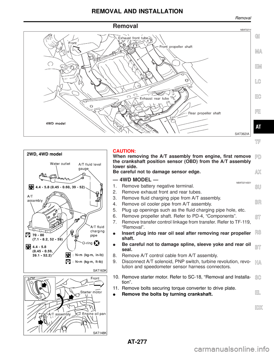
RemovalNBAT0214
SAT362IA
SAT163K
CAUTION:
When removing the A/T assembly from engine, first remove
the crankshaft position sensor (OBD) from the A/T assembly
lower side.
Be careful not to damage sensor edge.
Ð 4WD MODEL ÐNBAT0214S011. Remove battery negative terminal.
2. Remove exhaust front and rear tubes.
3. Remove fluid charging pipe from A/T assembly.
4. Remove oil cooler pipe from A/T assembly.
5. Plug up openings such as the fluid charging pipe hole, etc.
6. Remove propeller shaft. Refer to PD-4, ªComponentsº.
7. Remove transfer control linkage from transfer. Refer to TF-119,
ªRemovalº.
IInsert plug into rear oil seal after removing rear propeller
shaft.
IBe careful not to damage spline, sleeve yoke and rear oil
seal.
8. Remove A/T control cable from A/T assembly.
9. Disconnect A/T solenoid, PNP switch, turbine revolution, revo-
lution and speedometer sensor harness connectors.
SAT148K
10. Remove starter motor. Refer to SC-18, ªRemoval and Installa-
tionº.
11. Remove bolts securing torque converter to drive plate.
IRemove the bolts by turning crankshaft.
GI
MA
EM
LC
EC
FE
TF
PD
AX
SU
BR
ST
RS
BT
HA
SC
EL
IDX
REMOVAL AND INSTALLATION
Removal
AT-277
Page 283 of 2395
SAT801C
12. Support A/T and transfer assembly with a jack.
13. Remove rear engine mounting member from body and A/T
assembly. Tighten rear engine mounting member to the speci-
fied torque. Refer to EM-59, ªRear Engine Mountingº.
14. Remove bolts securing A/T assembly to engine.
ISecure torque converter to prevent it from dropping.
ISecure A/T assembly to a jack.
15. Lower A/T assembly with transfer.
SAT553J
SAT544J
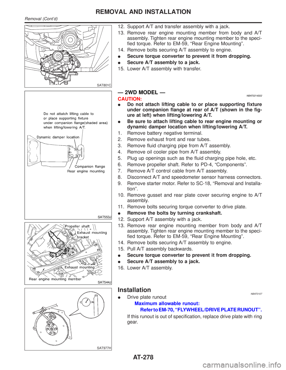
Ð 2WD MODEL ÐNBAT0214S02CAUTION:
IDo not attach lifting cable to or place supporting fixture
under companion flange at rear of A/T (shown in the fig-
ure at left) when lifting/lowering A/T.
IBe sure to attach lifting cable to rear engine mounting or
dynamic damper location when lifting/lowering A/T.
1. Remove battery negative terminal.
2. Remove exhaust front and rear tubes.
3. Remove fluid charging pipe from A/T assembly.
4. Remove oil cooler pipe from A/T assembly.
5. Plug up openings such as the fluid charging pipe hole, etc.
6. Remove propeller shaft. Refer to PD-4, ªComponentsº.
7. Remove A/T control cable from A/T assembly.
8. Disconnect A/T and speedometer sensor harness connectors.
9. Remove starter motor. Refer to SC-18, ªRemoval and Installa-
tionº.
10. Remove gusset and rear plate cover securing engine to A/T
assembly.
11. Remove bolts securing torque converter to drive plate.
IRemove the bolts by turning crankshaft.
12. Support A/T assembly with a jack.
13. Remove rear engine mounting member from body and A/T
assembly. Tighten rear engine mounting member to the speci-
fied torque. Refer to EM-59, ªRear Engine Mountingº.
14. Remove bolts securing A/T assembly to engine.
15. Pull A/T assembly backwards.
ISecure torque converter to prevent it from dropping.
ISecure A/T assembly to a jack.
16. Lower A/T assembly.
SAT977H
InstallationNBAT0107IDrive plate runout
Maximum allowable runout:
Refer to EM-70, ªFLYWHEEL/DRIVE PLATE RUNOUTº.
If this runout is out of specification, replace drive plate with ring
gear.
REMOVAL AND INSTALLATION
Removal (Cont'd)
AT-278
Page 623 of 2395
![INFINITI QX4 2001 Factory Service Manual Monitored item [Unit]ECM
input
signalsMain
signalsDescription Remarks
INT/A TEMP SE
[ÉC] or [ÉF]qqIThe intake air temperature determined
by the signal voltage of the intake air
temperature sensor is INFINITI QX4 2001 Factory Service Manual Monitored item [Unit]ECM
input
signalsMain
signalsDescription Remarks
INT/A TEMP SE
[ÉC] or [ÉF]qqIThe intake air temperature determined
by the signal voltage of the intake air
temperature sensor is](/img/42/57027/w960_57027-622.png)
Monitored item [Unit]ECM
input
signalsMain
signalsDescription Remarks
INT/A TEMP SE
[ÉC] or [ÉF]qqIThe intake air temperature determined
by the signal voltage of the intake air
temperature sensor is indicated.
EVAP SYS PRES [V]qIThe signal voltage of EVAP control sys-
tem pressure sensor is displayed.
ABSOL PRES/SE [V]qIThe signal voltage of the absolute pres-
sure sensor is displayed.
FUEL LEVEL SE [V]qIThe signal voltage of the fuel level sen-
sor is displayed.
START SIGNAL
[ON/OFF]qqIIndicates [ON/OFF] condition from the
starter signal.IAfter starting the engine, [OFF] is dis-
played regardless of the starter signal.
CLSD THL POS
[ON/OFF]qqIIndicates idle position [ON/OFF] com-
puted by ECM according to the throttle
position sensor signal.
CLSD THL/P SW
[ON/OFF]qIIndicates mechanical contact [ON/OFF]
condition of the closed throttle position
switch.
AIR COND SIG
[ON/OFF]qqIIndicates [ON/OFF] condition of the air
conditioner switch as determined by the
air conditioner signal.
P/N POSI SW
[ON/OFF]qqIIndicates [ON/OFF] condition from the
park/neutral position (PNP) switch sig-
nal.
PW/ST SIGNAL
[ON/OFF]qqI[ON/OFF] condition of the power steer-
ing oil pressure switch determined by
the power steering oil pressure signal is
indicated.
LOAD SIGNAL
[ON/OFF]qqIIndicates [ON/OFF] condition from the
electrical load signal and/or lighting
switch.
ON ... rear defogger is operating and/or
lighting switch is on.
OFF ... rear defogger is not operating
and lighting switch is not on.
IGNITION SW
[ON/OFF]qIIndicates [ON/OFF] condition from igni-
tion switch.
SWRL CONT S/V
[ON/OFF]qIThe control condition of the swirl con-
trol valve control solenoid valve (deter-
mined by ECM according to the input
signals) is indicated.
ION ... Swirl control valve is closed.
OFF ... Swirl control valve is opened.
INJ PULSE-B1
[msec]q
IIndicates the actual fuel injection pulse
width compensated by ECM according
to the input signals.IWhen the engine is stopped, a certain
computed value is indicated.
INJ PULSE-B2
[msec]
B/FUEL SCHDL
[msec]qIªBase fuel scheduleº indicates the fuel
injection pulse width programmed into
ECM, prior to any learned on board
correction.
ON BOARD DIAGNOSTIC SYSTEM DESCRIPTION
CONSULT-II (Cont'd)
EC-88
Page 655 of 2395
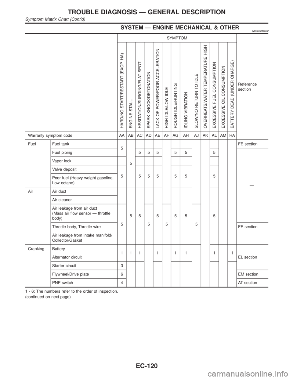
SYSTEM Ð ENGINE MECHANICAL & OTHERNBEC0041S02
SYMPTOM
Reference
section
HARD/NO START/RESTART (EXCP. HA)
ENGINE STALL
HESITATION/SURGING/FLAT SPOT
SPARK KNOCK/DETONATION
LACK OF POWER/POOR ACCELERATION
HIGH IDLE/LOW IDLE
ROUGH IDLE/HUNTING
IDLING VIBRATION
SLOW/NO RETURN TO IDLE
OVERHEATS/WATER TEMPERATURE HIGH
EXCESSIVE FUEL CONSUMPTION
EXCESSIVE OIL CONSUMPTION
BATTERY DEAD (UNDER CHARGE)
Warranty symptom code AA AB AC AD AE AF AG AH AJ AK AL AM HA
Fuel Fuel tank
5
5FE section
Fuel piping 5 5 5 5 5 5
Ð Vapor lock
Valve deposit
5 555 5 5 5
Poor fuel (Heavy weight gasoline,
Low octane)
Air Air duct
55555 5 Air cleaner
Air leakage from air duct
(Mass air flow sensor Ð throttle
body)
555 5
Throttle body, Throttle wireFE section
Air leakage from intake manifold/
Collector/GasketÐ
Cranking Battery
111111 11
EL section Alternator circuit
Starter circuit 3
Flywheel/Drive plate 6 EM section
PNP switch 4 AT section
1 - 6: The numbers refer to the order of inspection.
(continued on next page)
TROUBLE DIAGNOSIS Ð GENERAL DESCRIPTION
Symptom Matrix Chart (Cont'd)
EC-120
Page 870 of 2395
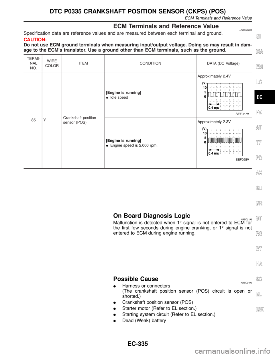
ECM Terminals and Reference Value=NBEC0664Specification data are reference values and are measured between each terminal and ground.
CAUTION:
Do not use ECM ground terminals when measuring input/output voltage. Doing so may result in dam-
age to the ECM's transistor. Use a ground other than ECM terminals, such as the ground.
TERMI-
NAL
NO.WIRE
COLORITEM CONDITION DATA (DC Voltage)
85 YCrankshaft position
sensor (POS)[Engine is running]
IIdle speedApproximately 2.4V
SEF057V
[Engine is running]
IEngine speed is 2,000 rpm.Approximately 2.3V
SEF058V
On Board Diagnosis LogicNBEC0193Malfunction is detected when 1É signal is not entered to ECM for
the first few seconds during engine cranking, or 1É signal is not
entered to ECM during engine running.
Possible CauseNBEC0493IHarness or connectors
(The crankshaft position sensor (POS) circuit is open or
shorted.)
ICrankshaft position sensor (POS)
IStarter motor (Refer to EL section.)
IStarting system circuit (Refer to EL section.)
IDead (Weak) battery
GI
MA
EM
LC
FE
AT
TF
PD
AX
SU
BR
ST
RS
BT
HA
SC
EL
IDX
DTC P0335 CRANKSHAFT POSITION SENSOR (CKPS) (POS)
ECM Terminals and Reference Value
EC-335
Page 878 of 2395
![INFINITI QX4 2001 Factory Service Manual Possible CauseNBEC0494IHarness or connectors
[The camshaft position sensor (PHASE) circuit is open or
shorted.]
ICamshaft position sensor (PHASE)
IStarter motor (Refer to SC section.)
IStarting system INFINITI QX4 2001 Factory Service Manual Possible CauseNBEC0494IHarness or connectors
[The camshaft position sensor (PHASE) circuit is open or
shorted.]
ICamshaft position sensor (PHASE)
IStarter motor (Refer to SC section.)
IStarting system](/img/42/57027/w960_57027-877.png)
Possible CauseNBEC0494IHarness or connectors
[The camshaft position sensor (PHASE) circuit is open or
shorted.]
ICamshaft position sensor (PHASE)
IStarter motor (Refer to SC section.)
IStarting system circuit (Refer to SC section.)
IDead (Weak) battery
DTC Confirmation ProcedureNBEC0200NOTE:
IPerform ªPROCEDURE FOR MALFUNCTION Aº first. If 1st
trip DTC cannot be confirmed, perform ªPROCEDURE
FOR MALFUNCTION B AND Cº.
IIf ªDTC Confirmation Procedureº has been previously
conducted, always turn ignition switch ªOFFº and wait at least
10 seconds before conducting the next test.
TESTING CONDITION:
Before performing the following procedure, confirm that bat-
tery voltage is more than 10.5V at idle.
SEF013Y
PROCEDURE FOR MALFUNCTION ANBEC0200S01With CONSULT-IINBEC0200S01011) Turn ignition switch ªONº.
2) Select ªDATA MONITORº mode with CONSULT-II.
3) Crank engine for at least 2 seconds.
4) If 1st trip DTC is detected, go to ªDiagnostic Procedureº,
EC-345.
With GSTNBEC0200S0102Follow the procedure ªWith CONSULT-IIº above.
SEF058Y
PROCEDURE FOR MALFUNCTION B AND CNBEC0200S02With CONSULT-IINBEC0200S02011) Turn ignition switch ªONº.
2) Select ªDATA MONITORº mode with CONSULT-II.
3) Start engine and run it for at least 2 seconds at idle speed.
4) If 1st trip DTC is detected, go to ªDiagnostic Procedureº,
EC-345.
With GSTNBEC0200S0202Follow the procedure ªWith CONSULT-IIº above.
GI
MA
EM
LC
FE
AT
TF
PD
AX
SU
BR
ST
RS
BT
HA
SC
EL
IDX
DTC P0340 CAMSHAFT POSITION SENSOR (CMPS) (PHASE)
Possible Cause
EC-343
Page 880 of 2395

Diagnostic ProcedureNBEC0202
1 CHECK STARTING SYSTEM
Turn ignition switch to ªSTARTº position.
Does the engine turn over?
Does the starter motor operate?
YesorNo
Ye s©GO TO 2.
No©Check starting system. (Refer to SC-10, ªSTARTING SYSTEMº.)
2 RETIGHTEN GROUND SCREWS
1. Turn ignition switch ªOFFº.
2. Loosen and retighten engine ground screws.
SEF959Y
©GO TO 3.
3 CHECK CMPS (PHASE) INPUT SIGNAL CIRCUIT FOR OPEN AND SHORT
1. Turn ignition switch ªOFFº.
2. Disconnect ECM harness connector and CMPS (PHASE) harness connector.
SEF982Y
3. Check harness continuity between CMPS (PHASE) terminal 2 and ECM terminals 66, 76. Refer to Wiring Diagram.
Continuity should exist.
4. Also check harness for short to ground and short to power.
OK or NG
OK©GO TO 4.
NG©Repair open circuit or short to ground or short to power in harness or connectors.
GI
MA
EM
LC
FE
AT
TF
PD
AX
SU
BR
ST
RS
BT
HA
SC
EL
IDX
DTC P0340 CAMSHAFT POSITION SENSOR (CMPS) (PHASE)
Diagnostic Procedure
EC-345
Page 1046 of 2395
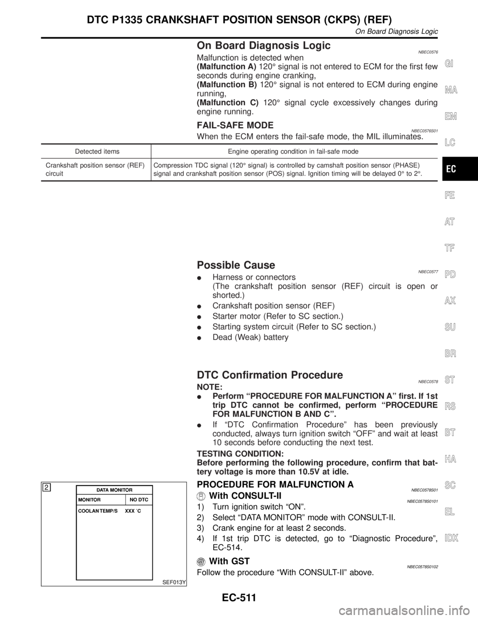
On Board Diagnosis LogicNBEC0576Malfunction is detected when
(Malfunction A)120É signal is not entered to ECM for the first few
seconds during engine cranking,
(Malfunction B)120É signal is not entered to ECM during engine
running,
(Malfunction C)120É signal cycle excessively changes during
engine running.
FAIL-SAFE MODENBEC0576S01When the ECM enters the fail-safe mode, the MIL illuminates.
Detected items Engine operating condition in fail-safe mode
Crankshaft position sensor (REF)
circuitCompression TDC signal (120É signal) is controlled by camshaft position sensor (PHASE)
signal and crankshaft position sensor (POS) signal. Ignition timing will be delayed 0É to 2É.
Possible CauseNBEC0577IHarness or connectors
(The crankshaft position sensor (REF) circuit is open or
shorted.)
ICrankshaft position sensor (REF)
IStarter motor (Refer to SC section.)
IStarting system circuit (Refer to SC section.)
IDead (Weak) battery
DTC Confirmation ProcedureNBEC0578NOTE:
IPerform ªPROCEDURE FOR MALFUNCTION Aº first. If 1st
trip DTC cannot be confirmed, perform ªPROCEDURE
FOR MALFUNCTION B AND Cº.
IIf ªDTC Confirmation Procedureº has been previously
conducted, always turn ignition switch ªOFFº and wait at least
10 seconds before conducting the next test.
TESTING CONDITION:
Before performing the following procedure, confirm that bat-
tery voltage is more than 10.5V at idle.
SEF013Y
PROCEDURE FOR MALFUNCTION ANBEC0578S01With CONSULT-IINBEC0578S01011) Turn ignition switch ªONº.
2) Select ªDATA MONITORº mode with CONSULT-II.
3) Crank engine for at least 2 seconds.
4) If 1st trip DTC is detected, go to ªDiagnostic Procedureº,
EC-514.
With GSTNBEC0578S0102Follow the procedure ªWith CONSULT-IIº above.
GI
MA
EM
LC
FE
AT
TF
PD
AX
SU
BR
ST
RS
BT
HA
SC
EL
IDX
DTC P1335 CRANKSHAFT POSITION SENSOR (CKPS) (REF)
On Board Diagnosis Logic
EC-511
Page 1158 of 2395

Diagnostic ProcedureNBEC0391
1 INSPECTION START
Do you have CONSULT-II?
YesorNo
Ye s©GO TO 2.
No©GO TO 3.
2 CHECK OVERALL FUNCTION
With CONSULT-II
1. Turn ignition switch ªONº.
2. Check ªSTART SIGNALº in ªDATA MONITORº mode with CONSULT-II under the following conditions.
SEF072Y
OK or NG
OK©INSPECTION END
NG©GO TO 4.
3 CHECK OVERALL FUNCTION
Without CONSULT-II
Check voltage between ECM terminal 42 and ground under the following conditions.
SEF362X
OK or NG
OK©INSPECTION END
NG©GO TO 4.
4 CHECK STARTING SYSTEM
Turn ignition switch ªOFFº, then turn it to ªSTARTº.
Does starter motor operate?
YesorNo
Ye s©GO TO 5.
No©Refer to SC-10, ªSTARTING SYSTEMº.
GI
MA
EM
LC
FE
AT
TF
PD
AX
SU
BR
ST
RS
BT
HA
SC
EL
IDX
START SIGNAL
Diagnostic Procedure
EC-623