starter INFINITI QX4 2001 Factory User Guide
[x] Cancel search | Manufacturer: INFINITI, Model Year: 2001, Model line: QX4, Model: INFINITI QX4 2001Pages: 2395, PDF Size: 43.2 MB
Page 1659 of 2395

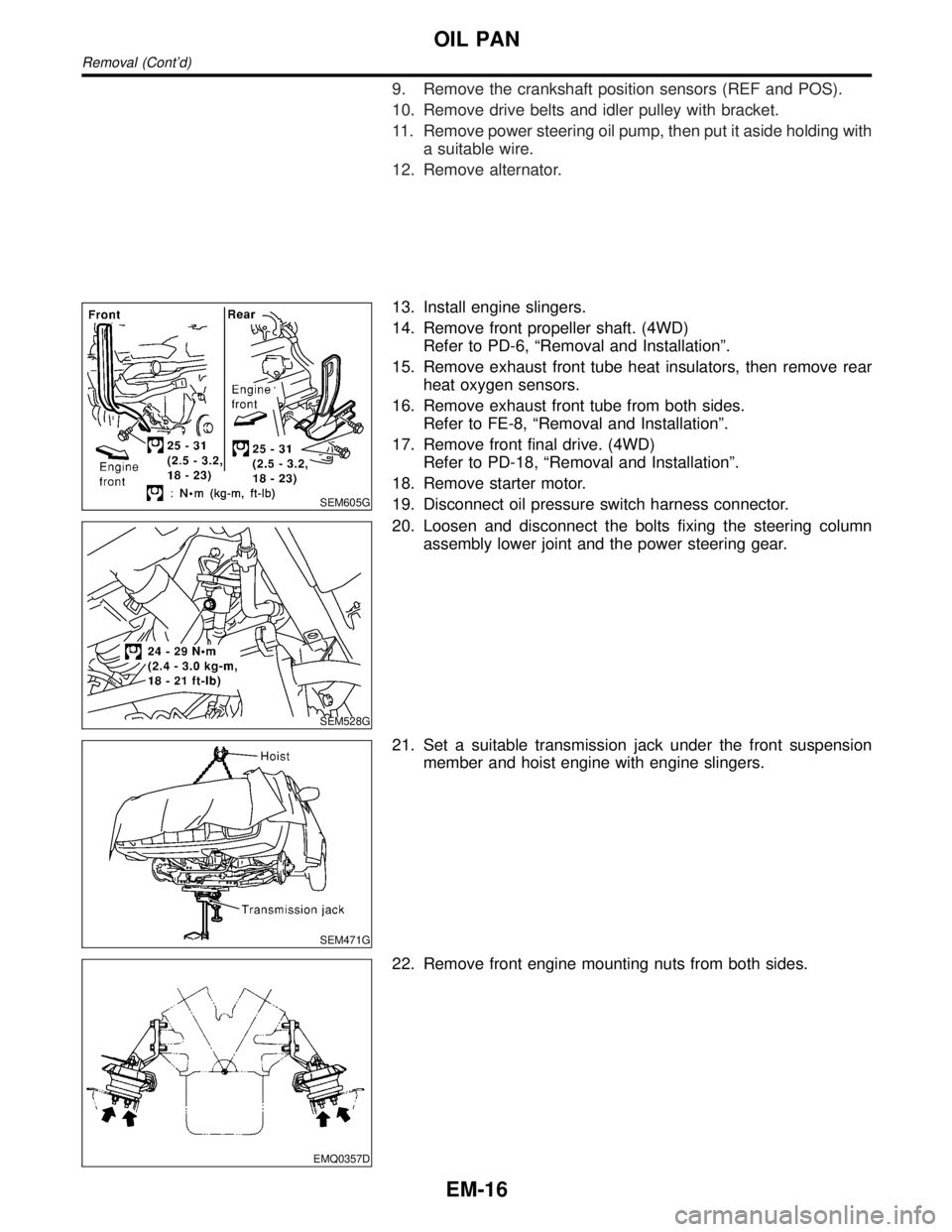
9. Remove the crankshaft position sensors (REF and POS).
10. Remove drive belts and idler pulley with bracket.
11. Remove power steering oil pump, then put it aside holding with
a suitable wire.
12. Remove alternator.
SEM605G
13. Install engine slingers.
14. Remove front propeller shaft. (4WD)
Refer to PD-6, ªRemoval and Installationº.
15. Remove exhaust front tube heat insulators, then remove rear
heat oxygen sensors.
16. Remove exhaust front tube from both sides.
Refer to FE-8, ªRemoval and Installationº.
17. Remove front final drive. (4WD)
Refer to PD-18, ªRemoval and Installationº.
18. Remove starter motor.
19. Disconnect oil pressure switch harness connector.
SEM528G
20. Loosen and disconnect the bolts fixing the steering column
assembly lower joint and the power steering gear.
SEM471G
21. Set a suitable transmission jack under the front suspension
member and hoist engine with engine slingers.
EMQ0357D
22. Remove front engine mounting nuts from both sides.
OIL PAN
Removal (Cont'd)
EM-16
Page 1668 of 2395

SEM415G
17. Disconnect injector harness connectors.
18. Remove fuel tube assembly in reverse order of installation.
Refer to EM-12, ªFuel Tubeº.
SEM416G
19. Remove ignition coils.
20. Remove RH and LH rocker covers from cylinder head.
SEM417G
21. Set No. 1 piston at TDC on the compression stroke by rotat-
ing crankshaft.
IAlign pointer with TDC mark on crankshaft pulley.
SEM418G
ICheck that intake and exhaust cam nose on No. 1 cylinder are
installed as shown left.
If not, turn the crankshaft one revolution (360É) and align as
above.
SEM485G
22. Remove starter motor, and set ring gear stopper using the
mounting bolt hole.
IBe careful not to damage the signal plate teeth.
GI
MA
LC
EC
FE
AT
TF
PD
AX
SU
BR
ST
RS
BT
HA
SC
EL
IDX
TIMING CHAIN
Removal (Cont'd)
EM-25
Page 1966 of 2395

Propeller shaft greasing .................................MA-23
Propeller shaft inspection ..............................MA-23
Propeller shaft on vehicle service ....................PD-6
Propeller shaft vibration ...................................PD-6
PST/SW - Wiring diagram ............................EC-635
R
Rack retainer adjustment ..................................ST-8
Radiator ....................................................LC-19, 21
Radio - See Audio.........................................EL-160
Rear air spoiler ...............................................BT-35
Rear axle ........................................................AX-17
Rear bumper ...................................................BT-15
Rear case (Transfer) .....................................TF-123
Rear combination lamp removal and
installation ...................................................BT-35
Rear cover packing replacement diff. ............PD-16
Rear door ........................................................BT-20
Rear drum brake ............................................BR-26
Rear heated oxygen sensor
(HO2S) .............................EC-247, 257, 267, 277
Rear heated oxygen sensor (HO2S)
heater ........................................................EC-286
Rear seat ........................................................BT-44
Rear seat belt ...................................................RS-5
Rear side window ...........................................BT-55
Rear suspension ............................................SU-15
Rear washer..................................................EL-141
Rear window defogger ..................................EL-151
Rear wiper.....................................................EL-141
REF - Wiring diagram ..................................EC-510
Refregerant pressure sensor ........................HA-111
Refrigerant connection precaution ...................HA-4
Refrigerant discharging evacuating
charging ....................................................HA-144
Refrigerant general precaution.........................HA-3
Refrigerant lines ...........................................HA-154
Refrigerant pressure sensor.........................EC-639
Refrigeration cycle..........................................HA-14
REMOTE - Wiring diagram ...........................EL-168
Removal and installation (A/T) ......................AT-277
Removal and installation (Transfer) ..............TF-119
Reverse clutch...............................................AT-314
Revolution sensor (A/T).................................AT-115
Ring gear diff. inspection .........................PD-23, 47
RO2H-L - Wiring diagram.............................EC-290
RO2H-R - Wiring diagram ............................EC-289
Road wheel size ..............................................GI-44
Roof trim .........................................................BT-32
Room lamp - See Interior lamp ......................EL-88
RRO2LH - Wiring diagram...EC-251, 261, 271, 281
RRO2RH - Wiring diagram ..EC-250, 260, 270, 280
S
SAE J1930 terminology list .............................GI-51
Screw jack .......................................................GI-45Seal - See Exterior .........................................BT-35
SEAT - Wiring diagram .................................EL-181
Seat belt inspection .............................MA-28, RS-7
Seat belt pre-tensioner .....................................RS-3
Seat belt pre-tensioner disposal ....................RS-22
Seat belt, front ..................................................RS-4
Seat belt, rear...................................................RS-5
Seat, front .......................................................BT-41
Seat, rear ........................................................BT-44
Self-diagnosis (Transfer) .................................TF-27
SHIFT - Wiring diagram ................................AT-266
Shift lock system ...........................................AT-265
Shift schedule ................................................AT-356
Shift solenoid valve A (A/T) ..AT-125, 137, 147, 171
Shift solenoid valve B (A/T) ..AT-125, 131, 147, 175
Shock absorber (rear) ....................................SU-18
Side air bag ....................................................RS-21
Side bearing preload (front final drive
4WD) ...........................................................PD-24
Side trim ..........................................................BT-28
Side window - See Rear side window ............BT-55
Smart entrance control unit ..........................EL-319
SMJ (super multiple junction) .......................Foldout
Spare tire size .................................................GI-44
Spark plug replacement .................................MA-19
Speedometer...................................................EL-94
Spiral cable.....................................................RS-17
Spot lamp ........................................................EL-88
Spring (Wheelarch) height ...............................SU-5
SROOF - Wiring diagram .............................EL-174
SRS - See Supplemental Restraint
System ........................................................RS-10
SRS - Wiring diagram ....................................RS-35
S/SIG - Wiring diagram ................................EC-622
Stabilizer bar (front)........................................SU-10
Stabilizer bar (rear) ........................................SU-20
Stall test (A/T) .................................................AT-59
Standardized relay ............................................EL-7
START - Wiring diagram.................................SC-11
Start signal ...................................................EC-621
Starter .............................................................SC-18
Starting system...............................................SC-10
Steering gear, linkage and transfer
gear inspection ...........................................MA-26
Steering linkage ..............................................ST-17
Steering switch................................................EL-30
Steering transfer gear .....................................ST-15
Steering wheel and column.............................ST-11
Steering wheel play ..........................................ST-7
Steering wheel turning force .............................ST-9
Stop lamp ........................................................EL-67
STOP/L - Wiring diagram................................EL-67
Strut (front) .......................................................SU-8
Sub-oil pump (Transfer) ................................TF-131
Sun gear (Transfer).......................................TF-134
Sun roof, electric ...........................................EL-173
Sunload sensor ............................................HA-135
Sunroof............................................................BT-45
Supplemental Restraint System .....................RS-10
Supplemental restraint system - Wiring
diagram .......................................................RS-35
GI
MA
EM
LC
EC
FE
AT
TF
PD
AX
SU
BR
ST
RS
BT
HA
SC
EL
ALPHABETICAL INDEX
IDX-7
Page 2152 of 2395

STARTING & CHARGING SYSTEM
SECTION
SC
CONTENTS
PRECAUTIONS...............................................................2
Supplemental Restraint System (SRS)²AIR
BAG²and²SEAT BELT PRE-TENSIONER²...............2
Wiring Diagrams and Trouble Diagnosis .....................2
PREPARATION...............................................................3
Special Service Tool ....................................................3
BATTERY.........................................................................4
How to Handle Battery ................................................4
METHODS OF PREVENTING OVER-DISCHARGE......4
CHECKING ELECTROLYTE LEVEL............................4
SPECIFIC GRAVITY CHECK......................................5
CHARGING THE BATTERY........................................6
Trouble Diagnoses with Battery/Starting/Charging
System Tester ..............................................................7
DIAGNOSTIC RESULT ITEM CHART..........................9
STARTING SYSTEM.....................................................10
System Description ....................................................10
Wiring Diagram - START -......................................... 11
Trouble Diagnoses with Battery/Starting/Charging
System Tester ............................................................12
DIAGNOSTIC RESULT ITEM CHART........................13
WORK FLOW..........................................................14
DIAGNOSTIC PROCEDURE 1..................................15
DIAGNOSTIC PROCEDURE 2..................................17
MINIMUM SPECIFICATION OF CRANKING
VOLTAGE REFERENCING COOLANT
TEMPERATURE
......................................................17
Construction ...............................................................18
Removal and Installation ...........................................18
Pinion/Clutch Check ..................................................18
CHARGING SYSTEM....................................................19
System Description ....................................................19
Wiring Diagram - CHARGE -.....................................20
Trouble Diagnoses with Battery/Starting/Charging
System Tester ............................................................21
DIAGNOSTIC RESULT ITEM CHART........................23
WORK FLOW..........................................................24
DIAGNOSTIC PROCEDURE 1..................................25
DIAGNOSTIC PROCEDURE 2..................................26
DIAGNOSTIC PROCEDURE 3..................................27
MALFUNCTION INDICATOR....................................27
Construction ...............................................................28
Removal and Installation ...........................................28
SERVICE DATA AND SPECIFICATIONS (SDS).........29
Battery........................................................................29
Starter ........................................................................29
Alternator ...................................................................29
GI
MA
EM
LC
EC
FE
AT
TF
PD
AX
SU
BR
ST
RS
BT
HA
EL
IDX
Page 2158 of 2395

Trouble Diagnoses with
Battery/Starting/Charging System Tester
NBSC0018CAUTION:
When working with batteries, always wear appropriate eye
protection.
NOTE:
ITo ensure a complete and thorough diagnosis, the battery,
starter and alternator test segments must be done as a set
from start to finish.
IIf battery surface charge is detected while testing, the tester
will prompt you to turn on the headlights to remove the surface
charge.
IIf necessary, the tester will prompt you to determine if the bat-
tery temperature is above or below 0ÉC (32ÉF). Choose the
appropriate selection by pressing the up or down arrow button,
then press ªENTERº to make the selection.
SEL404X
1. Turn off all loads on the vehicle electrical system. Clean or
repair as necessary.
2. Visually inspect the battery, battery terminals and cable ends
with ignition switch in ªOFFº position.
NOTE:
The contact surface between the battery terminals, cable ends and
tester leads must be clean for a valid test. A poor connection will
prevent testing and a ªCHECK CONNECTIONº message will
appear during the test procedures. If this occurs, clean the battery
post and terminals, reconnect them and restart the test.
3. Connect the red tester lead clamp to the positive battery
terminal, and the black to the negative terminal.
SEL405X
4. The tester will turn on automatically. Using the arrow keys,
select ªIN VEHICLEº on the tester and then press the ªENTERº
key.
GI
MA
EM
LC
EC
FE
AT
TF
PD
AX
SU
BR
ST
RS
BT
HA
EL
IDX
BATTERY
Trouble Diagnoses with Battery/Starting/Charging System Tester
SC-7
Page 2161 of 2395

System DescriptionNBSC0004Power is supplied at all times
Ito ignition switch terminal 1
Ithrough 40A fusible link (lettere, located in the fuse and fusible link box).
With the ignition switch in the ON or START position, power is supplied through 10A fuse [No. 18, located in
the fuse block (J/B)].
Ito park/neutral position relay terminal 1.
Also, with the ignition switch in the START position, power is supplied
Ifrom ignition switch terminal 5
Ito park/neutral position relay terminal 6.
With the selector lever in the P or N position, ground is supplied
Ito park/neutral position relay terminal 2 through the park/neutral position switch.
Then park/neutral position relay is energized and power is supplied
Ifrom park/neutral position relay terminal 7
Ito terminal 2 of the starter motor windings.
The starter motor plunger closes and provides a closed circuit between the battery and starter motor. The
starter motor is grounded to the engine block. With power and ground supplied, cranking occurs and the engine
starts.
STARTING SYSTEM
System Description
SC-10
Page 2163 of 2395

Trouble Diagnoses with
Battery/Starting/Charging System Tester
NBSC0019NOTE:
To ensure a complete and thorough diagnosis, the battery, starter
and alternator test segments must be done as a set from start to
finish.
SEL408X
1. Turn off all loads on the vehicle electrical system.
2. Perform battery test with Battery/Starting/Charging system
tester. Refer to SC-7.
3. Press ªENTERº to begin the starting system test.
SEL409X
4. Start the engine.
SEL410X
5. Diagnosis result is displayed on the tester. Refer to ªDIAG-
NOSTIC RESULT ITEM CHARTº, SC-13.
NOTE:
IIf the starter performs normally but the engine does not start,
perform engine diagnosis.
IFor intermittent ªNO CRANKº or ªNO STARTER OPERATIONº
incidents, go to DIAGNOSTIC PROCEDURE 2.
STARTING SYSTEM
Trouble Diagnoses with Battery/Starting/Charging System Tester
SC-12
Page 2166 of 2395

DIAGNOSTIC PROCEDURE 1NBSC0019S03Check ªBº Terminal CircuitNBSC0019S0301
1 CHECK POWER SUPPLY FOR STARTER MOTOR ªBº TERMINAL
1. Remove the fuel pump fuse.
2. Crank or start the engine (where possible) until the fuel pressure is released.
3. Turn the ignition OFF.
4. Check that the starter motor terminal 1 connection is clean and tight.
5. Check voltage between starter motor terminal 1 and ground using a digital circuit tester.
SEL412X
OK or NG
OK©GO TO 2.
NG©Check harness between the battery and the starter motor for open circuit.
2 CHECK BATTERY CABLE CONNECTION QUALITY (VOLTAGE DROP TEST)
1. Check voltage between starter motor terminal 1 and battery positive terminal using a digital circuit tester.
SEL413X
OK or NG
OK©GO TO 3.
NG©Check harness between the battery and the starter motor for poor continuity.
GI
MA
EM
LC
EC
FE
AT
TF
PD
AX
SU
BR
ST
RS
BT
HA
EL
IDX
STARTING SYSTEM
Trouble Diagnoses with Battery/Starting/Charging System Tester (Cont'd)
SC-15
Page 2167 of 2395

3 CHECK STARTER MOTOR GROUND CIRCUIT (VOLTAGE DROP TEST)
1. Check voltage between starter motor case and battery negative terminal using a digital circuit tester.
SEL414X
OK or NG
OK©Starter motor ªBº terminal circuit is OK. Further inspection necessary. Refer to ªWORK
FLOWº, SC-14.
NG©Check the starter motor case and ground for poor continuity.
STARTING SYSTEM
Trouble Diagnoses with Battery/Starting/Charging System Tester (Cont'd)
SC-16
Page 2168 of 2395

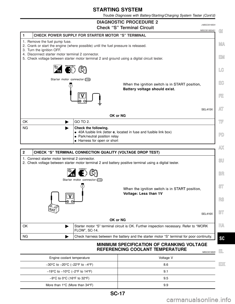
DIAGNOSTIC PROCEDURE 2=NBSC0019S04Check ªSº Terminal CircuitNBSC0019S0401
1 CHECK POWER SUPPLY FOR STARTER MOTOR ªSº TERMINAL
1. Remove the fuel pump fuse.
2. Crank or start the engine (where possible) until the fuel pressure is released.
3. Turn the ignition OFF.
4. Disconnect starter motor terminal 2 connector.
5. Check voltage between starter motor terminal 2 and ground using a digital circuit tester.
SEL415X
OK or NG
OK©GO TO 2.
NG©Check the following.
I40A fusible link (lettere, located in fuse and fusible link box)
IPark/neutral position relay
IHarness for open or short
2 CHECK ªSº TERMINAL CONNECTION QUALITY (VOLTAGE DROP TEST)
1. Connect starter motor terminal 2 connector.
2. Check voltage between starter motor terminal 2 and battery positive terminal using a digital tester.
SEL416X
OK or NG
OK©Starter motor ªSº terminal circuit is OK. Further inspection necessary. Refer to ªWORK
FLOWº, SC-14.
NG©Check harness between the battery and the starter motor ªSº terminal for poor continuity.
MINIMUM SPECIFICATION OF CRANKING VOLTAGE
REFERENCING COOLANT TEMPERATURE
NBSC0019S05
Engine coolant temperature Voltage V
þ30ÉC to þ20ÉC (þ22ÉF to þ4ÉF) 8.6
þ19ÉC to þ10ÉC (þ2ÉF to 14ÉF) 9.1
þ9ÉC to 0ÉC (16ÉF to 32ÉF) 9.5
More than 1ÉC (More than 34ÉF) 9.9
GI
MA
EM
LC
EC
FE
AT
TF
PD
AX
SU
BR
ST
RS
BT
HA
EL
IDX
STARTING SYSTEM
Trouble Diagnoses with Battery/Starting/Charging System Tester (Cont'd)
SC-17