steering INFINITI QX56 2007 Factory Service Manual
[x] Cancel search | Manufacturer: INFINITI, Model Year: 2007, Model line: QX56, Model: INFINITI QX56 2007Pages: 3061, PDF Size: 64.56 MB
Page 2512 of 3061
POWER STEERING OIL PUMP
PS-21
< SERVICE INFORMATION >
C
D
E
F
H
I
J
K
L
MA
B
PS
N
O
P
POWER STEERING OIL PUMP
On-Vehicle Inspection and ServiceINFOID:0000000003532831
CHECKING RELIEF OIL PRESSURE
CAUTION:
Before starting work, confirm belt tension is proper.
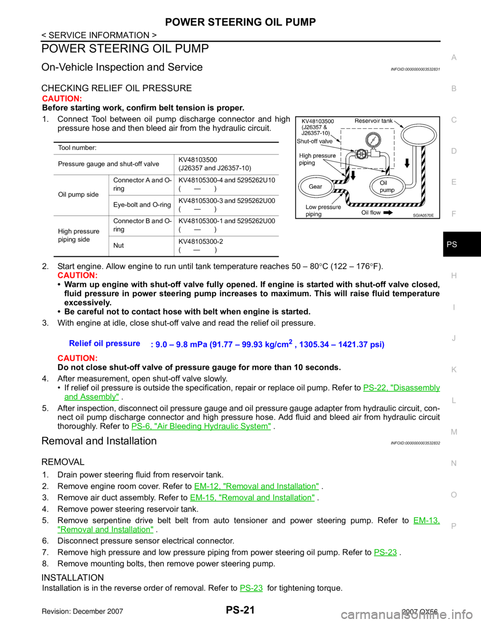
1. Connect Tool between oil pump discharge connector and high
pressure hose and then bleed air from the hydraulic circuit.
2. Start engine. Allow engine to run until tank temperature reaches 50 – 80°C (122 – 176°F).
CAUTION:
• Warm up engine with shut-off valve fully opened. If engine is started with shut-off valve closed,
fluid pressure in power steering pump increases to maximum. This will raise fluid temperature
excessively.
• Be careful not to contact hose with belt when engine is started.
3. With engine at idle, close shut-off valve and read the relief oil pressure.
CAUTION:
Do not close shut-off valve of pressure gauge for more than 10 seconds.
4. After measurement, open shut-off valve slowly.
• If relief oil pressure is outside the specification, repair or replace oil pump. Refer to PS-22, "
Disassembly
and Assembly" .
5. After inspection, disconnect oil pressure gauge and oil pressure gauge adapter from hydraulic circuit, con-
nect oil pump discharge connector and high pressure hose. Add fluid and bleed air from hydraulic circuit
thoroughly. Refer to PS-6, "
Air Bleeding Hydraulic System" .
Removal and InstallationINFOID:0000000003532832
REMOVAL
1. Drain power steering fluid from reservoir tank.
2. Remove engine room cover. Refer to EM-12, "
Removal and Installation" .
3. Remove air duct assembly. Refer to EM-15, "
Removal and Installation" .
4. Remove power steering reservoir tank.
5. Remove serpentine drive belt belt from auto tensioner and power steering pump. Refer to EM-13,
"Removal and Installation" .
6. Disconnect pressure sensor electrical connector.
7. Remove high pressure and low pressure piping from power steering oil pump. Refer to PS-23
.
8. Remove mounting bolts, then remove power steering pump.
INSTALLATION
Installation is in the reverse order of removal. Refer to PS-23 for tightening torque.
Tool number:
Pressure gauge and shut-off valveKV48103500
(J26357 and J26357-10)
Oil pump sideConnector A and O-
ringKV48105300-4 and 5295262U10
(—)
Eye-bolt and O-ringKV48105300-3 and 5295262U00
(—)
High pressure
piping sideConnector B and O-
ringKV48105300-1 and 5295262U00
(—)
NutKV48105300-2
( — )
SGIA0570E
Relief oil pressure
: 9.0 – 9.8 mPa (91.77 – 99.93 kg/cm2 , 1305.34 – 1421.37 psi)
Page 2513 of 3061

PS-22
< SERVICE INFORMATION >
POWER STEERING OIL PUMP
• After installation, bleed air. Refer to PS-6, "Air Bleeding Hydraulic System" .
NOTE:
Belt tension is automatic and requires no adjustment.
Disassembly and AssemblyINFOID:0000000003532833
INSPECTION BEFORE DISASSEMBLY
Disassemble the power steering oil pump only if the following items are found.
• Deformed or damaged pulley, bracket, connector or suction pipe.
• Oil leakage from the suction pipe or connector.
DISASSEMBLY
NOTE:
Mount the power steering oil pump in a vise as needed.
1. Remove the connector bolt, connector and copper washers.
CAUTION:
Do not reuse the copper washers.
2. Remove the suction pipe and O-ring.
CAUTION:
Do not reuse the O-ring.
3. Remove the pulley nut and pulley.
4. Remove the bracket bolts and bracket.
INSPECTION AFTER DISASSEMBLY
Body Assembly Inspection
Check the power steering oil pump body assembly for damage. If any damage is found, replace with a new
power steering oil pump assembly.
ASSEMBLY
Assembly is in the reverse order of disassembly.
CAUTION:
• Do not reuse the copper gaskets
• Do not reuse the O-ring. Apply a coat of Genuine Nissan PSF or equivalent to the O-ring.
1. Bracket 2. Spring washer 3. Pulley
4. Power steering pump 5. High pressure hose bracket 6. O-ring
7. Suction pipe⇐Front
LGIA0038E
Page 2514 of 3061

HYDRAULIC LINE
PS-23
< SERVICE INFORMATION >
C
D
E
F
H
I
J
K
L
MA
B
PS
N
O
P
HYDRAULIC LINE
Removal and InstallationINFOID:0000000003532834
Refer to the following illustration for hydralic line removal.
Installation is in the reverse order of removal.
1. Reservoir tank 2. Suction hose 3. High pressure hose
4. Oil cooler 5. Steering gear assembly 6. Reservoir tank bracket
7. Eye bolt
WGIA0096E
Page 2515 of 3061
PS-24
< SERVICE INFORMATION >
HYDRAULIC LINE
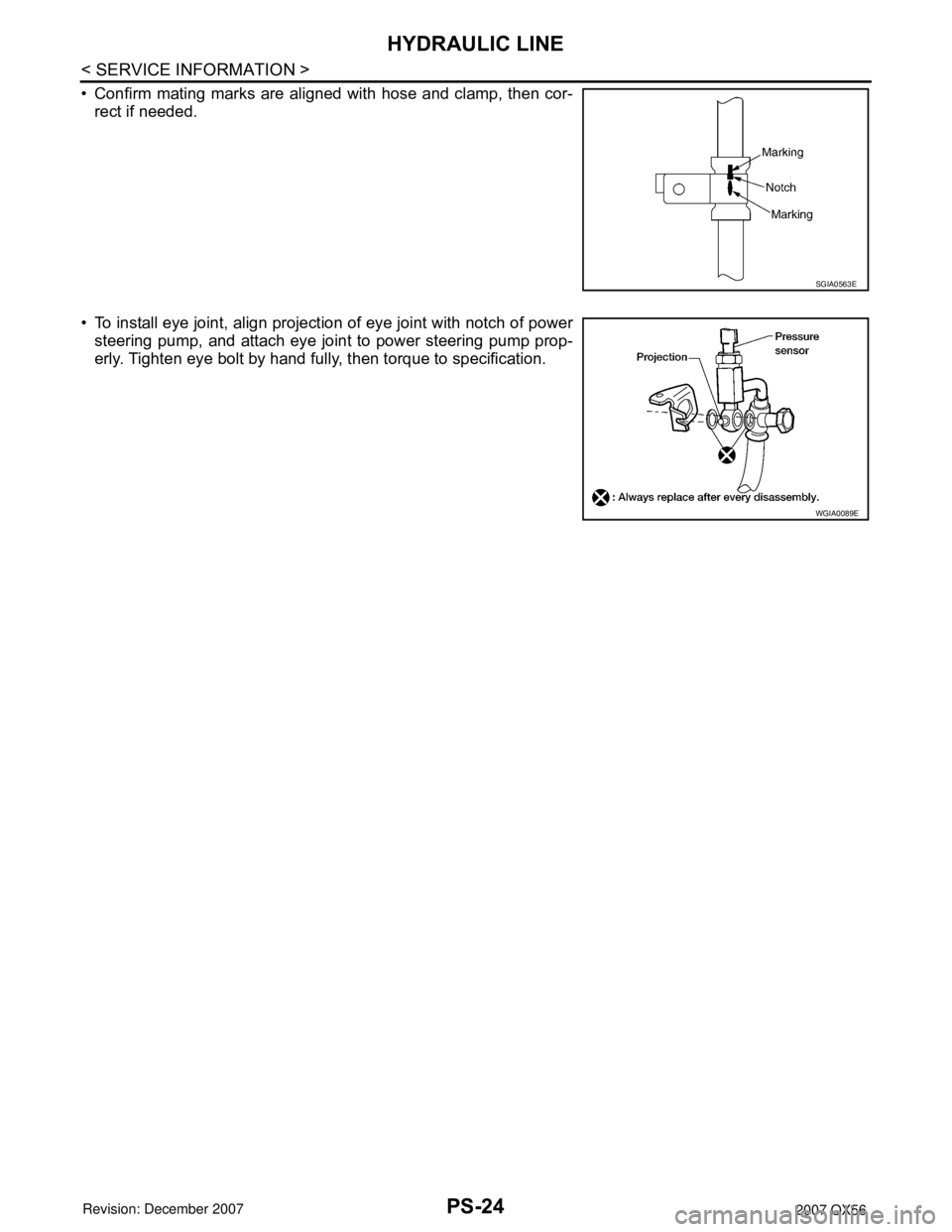
• Confirm mating marks are aligned with hose and clamp, then cor-
rect if needed.
• To install eye joint, align projection of eye joint with notch of power
steering pump, and attach eye joint to power steering pump prop-
erly. Tighten eye bolt by hand fully, then torque to specification.
SGIA0563E
WGIA0089E
Page 2516 of 3061

SERVICE DATA AND SPECIFICATIONS (SDS)
PS-25
< SERVICE INFORMATION >
C
D
E
F
H
I
J
K
L
MA
B
PS
N
O
P
SERVICE DATA AND SPECIFICATIONS (SDS)
Steering WheelINFOID:0000000003532835
Steering ColumnINFOID:0000000003532836
Inspection After Assembly
Unit: mm (in)
Inspection After Removal
Unit: mm (in)
Inspection After Installation
End play of the axial direction for steering wheel 0 mm (0 in)
Steering wheel play on the outer circumference 0 − 35 mm (0 − 1.38 in)
Steering wheel turning force 39 N (4 kg-f, 9 lb-f) or less
Steering column length “L”610 (24.02)
WGIA0080E
Steering column length “L2”262 (10.31)
Steering column length “L1” 158 (6.22)
Range “A”61.3 mm (2.41 in)
SGIA0475E
WGIA0083E
Page 2517 of 3061
PS-26
< SERVICE INFORMATION >
SERVICE DATA AND SPECIFICATIONS (SDS)
Steering Outer Socket and Inner Socket
INFOID:0000000003532837
Unit: mm (in)
Steering GearINFOID:0000000003532838
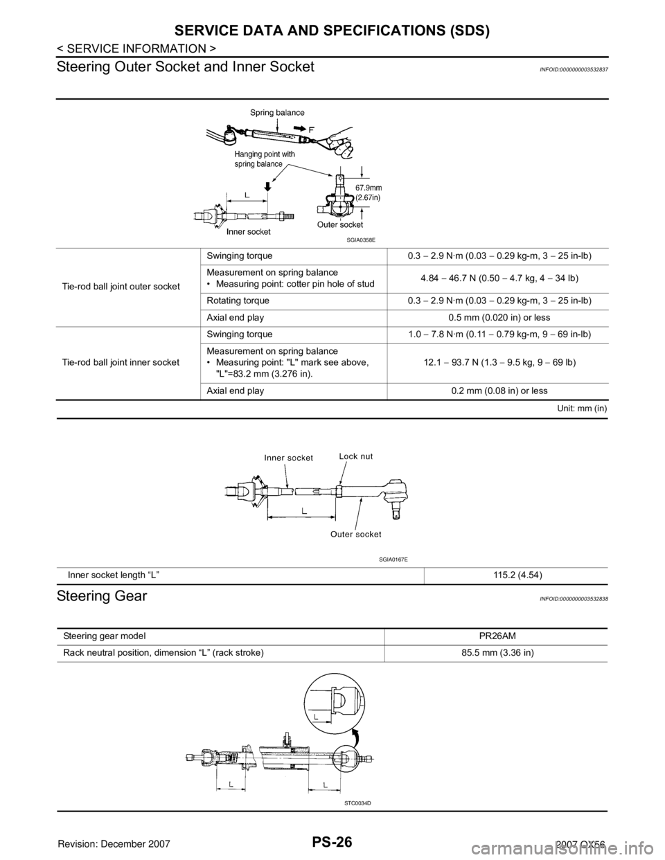
Tie-rod ball joint outer socketSwinging torque 0.3 − 2.9 N·m (0.03 − 0.29 kg-m, 3 − 25 in-lb)
Measurement on spring balance
• Measuring point: cotter pin hole of stud4.84 − 46.7 N (0.50 − 4.7 kg, 4 − 34 lb)
Rotating torque 0.3 − 2.9 N·m (0.03 − 0.29 kg-m, 3 − 25 in-lb)
Axial end play 0.5 mm (0.020 in) or less
Tie-rod ball joint inner socketSwinging torque 1.0 − 7.8 N·m (0.11 − 0.79 kg-m, 9 − 69 in-lb)
Measurement on spring balance
• Measuring point: "L" mark see above,
"L"=83.2 mm (3.276 in).12.1 − 93.7 N (1.3 − 9.5 kg, 9 − 69 lb)
Axial end play 0.2 mm (0.08 in) or less
SGIA0358E
Inner socket length “L” 115.2 (4.54)
SGIA0167E
Steering gear modelPR26AM
Rack neutral position, dimension “L” (rack stroke) 85.5 mm (3.36 in)
STC0034D
Page 2518 of 3061

SERVICE DATA AND SPECIFICATIONS (SDS)
PS-27
< SERVICE INFORMATION >
C
D
E
F
H
I
J
K
L
MA
B
PS
N
O
P
Oil PumpINFOID:0000000003532839
Steering FluidINFOID:0000000003532840
Rack sliding forceAt the neutral point:
Range within ± 11.5 mm
(±0.453 in) from the neutral
position
(in power ON)Area average value 147 − 211 N (14.99 − 21.52 kg, 33.1 − 47.52 lb)
Allowable variation 98 N (10 kg, 22 lb) or less
Whole area (in power OFF)Peak value 294 N (30.0 kg, 66 lb) or less
Allowable variation 147 N (16 kg, 35 lb) or less Steering gear modelPR26AM
Relief oil pressure
9.0 − 9.8 mPa (91.77 − 99.93 kg/cm2, 1305.34 − 1421.37 psi)
Fluid capacity
Approx. 1.0 (1-1/8 US qt, 7/8 Imp qt)
Page 2522 of 3061
RAX-4
< SERVICE INFORMATION >
NOISE, VIBRATION AND HARSHNESS (NVH) TROUBLESHOOTING
NOISE, VIBRATION AND HARSHNESS (NVH) TROUBLESHOOTING
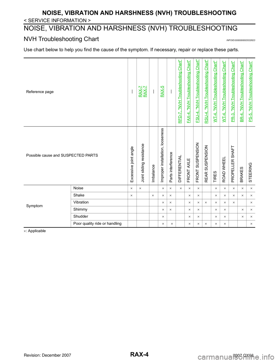
NVH Troubleshooting ChartINFOID:0000000003532623
Use chart below to help you find the cause of the symptom. If necessary, repair or replace these parts.
×: ApplicableReference page
—
RAX-7RAX-7—
RAX-5—
RFD-7, "
NVH Troubleshooting Chart
"
FAX-4, "
NVH Troubleshooting Chart
"
FSU-4, "
NVH Troubleshooting Chart
"
RSU-4, "
NVH Troubleshooting Chart
"
WT-4, "
NVH Troubleshooting Chart
"
WT-4, "
NVH Troubleshooting Chart
"
PR-3, "
NVH Troubleshooting Chart
"
BR-4, "
NVH Troubleshooting Chart
"
PS-5, "
NVH Troubleshooting Chart
"
Possible cause and SUSPECTED PARTS
Excessive joint angle
Joint sliding resistance
Imbalance
Improper installation, looseness
Parts interference
DIFFERENTIAL
FRONT AXLE
FRONT SUSPENSION
REAR SUSPENSION
TIRES
ROAD WHEEL
PROPELLER SHAFT
BRAKES
STEERING
SymptomNoise×× ×× ××× ×××××
Shake× × ×× ×× ×××××
Vibration×× ××× ××× ×
Shimmy×× ×× ×× ××
Shudder×××××××
Poor quality ride or handling×× ××× ×× ×
Page 2542 of 3061

RF-10
< SERVICE INFORMATION >
SUNROOF
SUNROOF
Component Parts and Harness Connector LocationINFOID:0000000003533095
System DescriptionINFOID:0000000003533096
OUTLINE
Electric sunroof system consists of
• Front door switches
• Sunroof switch
• Sunroof motor assembly
• BCM (body control module)
BCM supplies power to the sunroof motor. Sunroof operation depends on sunroof switch condition.
OPERATION
Power is supplied at all times
• through 50A fusible link (letter f, located in the fuse and fusible link box)
• to BCM terminal 70 and
• through BCM terminal 69
• to sunroof motor assembly terminal 5.
With ignition switch in ON or START position, power is supplied
• through 10A fuse (No. 59, located in the fuse and relay box)
• to BCM terminal 38.
Ground is supplied
• to BCM terminal 67 and
• to sunroof motor assembly terminal 7
• through grounds M57, M61 and M79.
TILT UP OPERATION
When the tilt switch is operated for tilt up, ground is supplied
• to sunroof motor assembly terminal 4
LIIA2398E
1. Sunroof switch R104 2. Steering column 3. BCM M18, M19, M20
4. Sunroof motor harness connector R4 5. Sunroof motor assembly 6. Front door switch
LH B8
RH 108
Page 2564 of 3061
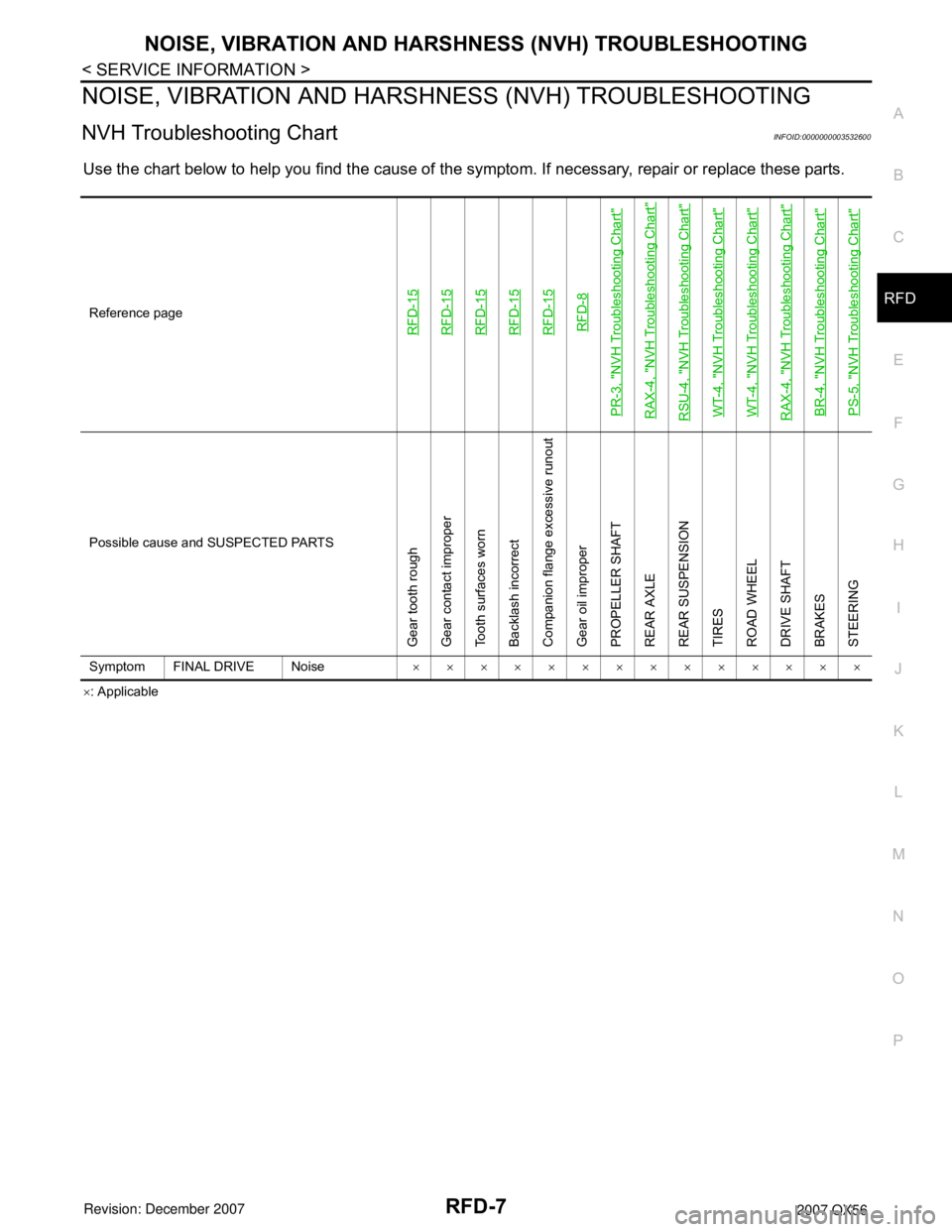
NOISE, VIBRATION AND HARSHNESS (NVH) TROUBLESHOOTING
RFD-7
< SERVICE INFORMATION >
C
E
F
G
H
I
J
K
L
MA
B
RFD
N
O
P
NOISE, VIBRATION AND HARSHNESS (NVH) TROUBLESHOOTING
NVH Troubleshooting ChartINFOID:0000000003532600
Use the chart below to help you find the cause of the symptom. If necessary, repair or replace these parts.
×: Applicable Reference page
RFD-15RFD-15RFD-15RFD-15RFD-15RFD-8
PR-3, "
NVH Troubleshooting Chart
"
RAX-4, "
NVH Troubleshooting Chart
"
RSU-4, "
NVH Troubleshooting Chart
"
WT-4, "
NVH Troubleshooting Chart
"
WT-4, "
NVH Troubleshooting Chart
"
RAX-4, "
NVH Troubleshooting Chart
"
BR-4, "
NVH Troubleshooting Chart
"
PS-5, "
NVH Troubleshooting Chart
"
Possible cause and SUSPECTED PARTS
Gear tooth rough
Gear contact improper
Tooth surfaces worn
Backlash incorrect
Companion flange excessive runout
Gear oil improper
PROPELLER SHAFT
REAR AXLE
REAR SUSPENSION
TIRES
ROAD WHEEL
DRIVE SHAFT
BRAKES
STEERING
Symptom FINAL DRIVE Noise××××××××××××××