Starter Relay INFINITI QX56 2007 Factory User Guide
[x] Cancel search | Manufacturer: INFINITI, Model Year: 2007, Model line: QX56, Model: INFINITI QX56 2007Pages: 3061, PDF Size: 64.56 MB
Page 165 of 3061

DTC P0615 START SIGNAL CIRCUIT
AT-95
< SERVICE INFORMATION >
D
E
F
G
H
I
J
K
L
MA
B
AT
N
O
P
Wiring Diagram - AT - STSIGINFOID:0000000003532271
TCM Input/Output Signal Reference Values
Refer to AT-82, "TCM Input/Output Signal Reference Value".
Diagnosis ProcedureINFOID:0000000003532272
1.CHECK STARTER RELAY
BCWA0321E
Page 166 of 3061

AT-96
< SERVICE INFORMATION >
DTC P0615 START SIGNAL CIRCUIT
With CONSULT-II
1. Turn ignition switch “ON”. (Do not start engine.)
2. Select “SELECTION FROM MENU” in “DATA MONITOR” mode
for “A/T” with CONSULT-II and check monitor “STARTER
RELAY” ON/OFF.
Without CONSULT-II
1. Turn ignition switch “ON”. (Do not start engine.)
2. Check voltage between the IPDM E/R connector and ground.
OK or NG
OK >> GO TO 5.
NG >> GO TO 2.
2.CHECK HARNESS BETWEEN A/T ASSEMBLY HARNESS CONNECTOR AND IPDM E/R CONECTOR.
1. Turn ignition switch OFF.
2. Disconnect A/T assembly harness connector and IPDM E/R
connector.
3. Check continuity between A/T assembly harness connector and
IPDM E/R connector.
4. If OK, check harness for short to ground and short to power.
5. Reinstall any part removed.
OK or NG
OK >> GO TO 3.
NG >> Repair open circuit or short to ground or short to power in harness or connectors.
3.CHECK TERMINAL CORD ASSEMBLY
1. Remove control valve with TCM. Refer to AT-210, "
Control Valve with TCM and A/T Fluid Temperature
Sensor 2".
2. Disconnect A/T assembly harness connector and TCM connector.
3. Check continuity between A/T assembly harness connector ter-
minal and TCM connector terminal.
4. If OK, check harness for short to ground and short to power.
5. Reinstall any part removed.
OK or NG
Item name Condition Display value
STARTER RELAYSelector lever in "N'', "P'' positions. ON
Selector lever in other positions. OFF
PCIA0056E
Item Terminal Shift position Voltage (Approx.)
Starter re-
lay48 Ground"N'' and "P'' Battery voltage
"R'' and "D'' 0V
LCIA0320E
Item Connector Terminal Continuity
A/T assembly harness con-
nectorF9 9
Ye s
IPDM E/R connector E122 48
WCIA0427E
Item Connector Terminal Continuity
A/T assembly harness con-
nectorF9 9
Ye s
TCM connector F502 8
SCIA5440E
Page 167 of 3061

DTC P0615 START SIGNAL CIRCUIT
AT-97
< SERVICE INFORMATION >
D
E
F
G
H
I
J
K
L
MA
B
AT
N
O
P
OK >> GO TO 4.
NG >> Replace open circuit or short to ground and short to power in harness or connectors.
4.DETECT MALFUNCTIONING ITEM
Check the following items:
• Starter relay, Refer to SC-9
.
• IPDM E/R, Refer to PG-17
.
OK or NG
OK >> Replace the control valve with TCM. Refer to AT-210, "Control Valve with TCM and A/T Fluid Tem-
perature Sensor 2"
G >> Repair or replace damaged parts.
5.CHECK DTC
Perform “DTC Confirmation Procedure”.
• Refer to AT-91, "
DTC Confirmation Procedure".
OK or NG
OK >>INSPECTION END
NG >> GO TO 2.
Page 1428 of 3061
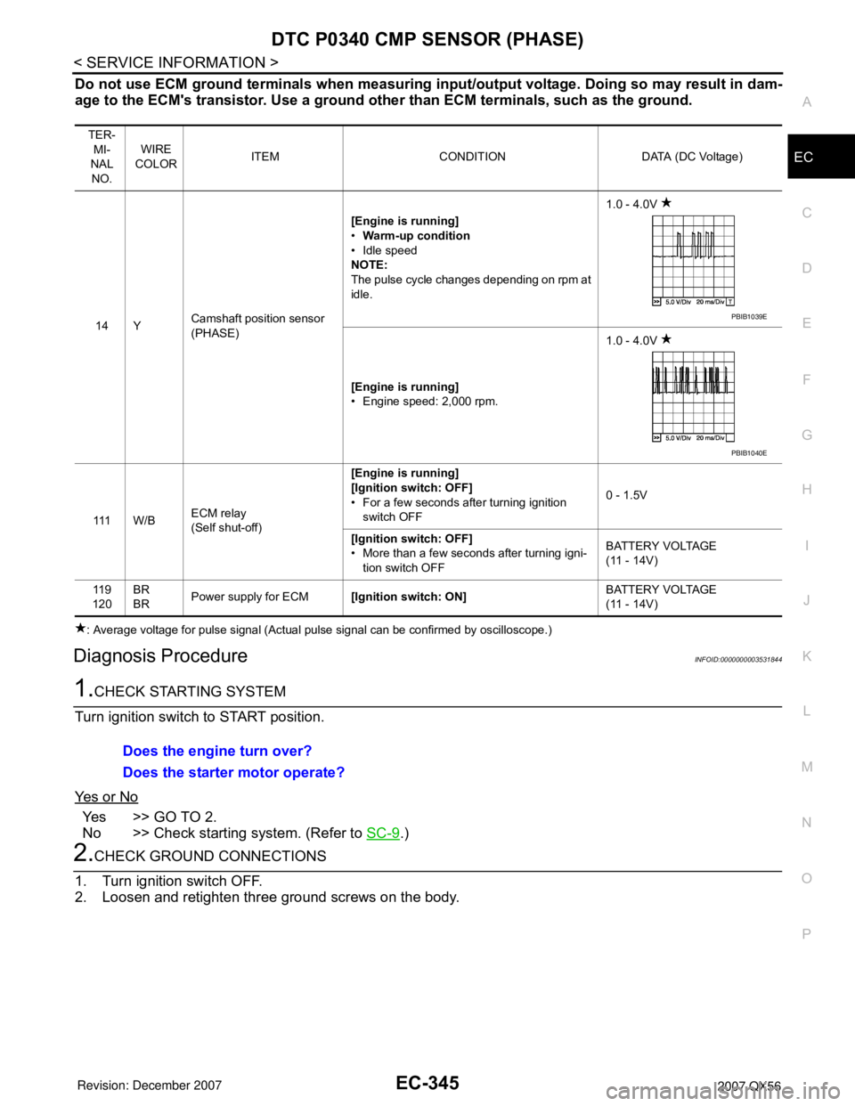
DTC P0340 CMP SENSOR (PHASE)
EC-345
< SERVICE INFORMATION >
C
D
E
F
G
H
I
J
K
L
MA
EC
N
P O
Do not use ECM ground terminals when measuring input/output voltage. Doing so may result in dam-
age to the ECM's transistor. Use a ground other than ECM terminals, such as the ground.
: Average voltage for pulse signal (Actual pulse signal can be confirmed by oscilloscope.)
Diagnosis ProcedureINFOID:0000000003531844
1.CHECK STARTING SYSTEM
Turn ignition switch to START position.
Ye s o r N o
Yes >> GO TO 2.
No >> Check starting system. (Refer to SC-9
.)
2.CHECK GROUND CONNECTIONS
1. Turn ignition switch OFF.
2. Loosen and retighten three ground screws on the body.
TER-
MI-
NAL
NO.WIRE
COLORITEM CONDITION DATA (DC Voltage)
14 YCamshaft position sensor
(PHASE)[Engine is running]
•Warm-up condition
• Idle speed
NOTE:
The pulse cycle changes depending on rpm at
idle.1.0 - 4.0V
[Engine is running]
• Engine speed: 2,000 rpm.1.0 - 4.0V
111 W / BECM relay
(Self shut-off)[Engine is running]
[Ignition switch: OFF]
• For a few seconds after turning ignition
switch OFF0 - 1.5V
[Ignition switch: OFF]
• More than a few seconds after turning igni-
tion switch OFFBATTERY VOLTAGE
(11 - 14V)
11 9
120BR
BRPower supply for ECM[Ignition switch: ON]BATTERY VOLTAGE
(11 - 14V)
PBIB1039E
PBIB1040E
Does the engine turn over?
Does the starter motor operate?
Page 2419 of 3061

IPDM E/R (INTELLIGENT POWER DISTRIBUTION MODULE ENGINE ROOM)
PG-17
< SERVICE INFORMATION >
C
D
E
F
G
H
I
J
L
MA
B
PG
N
O
P
IPDM E/R (INTELLIGENT POWER DISTRIBUTION MODULE ENGINE
ROOM)
System DescriptionINFOID:0000000003533835
• IPDM E/R (Intelligent Power Distribution Module Engine Room) integrates the relay box and fuse block
which were originally placed in engine compartment. It controls integrated relays via IPDM E/R control cir-
cuits.
• IPDM E/R-integrated control circuits perform ON-OFF operation of relays, CAN communication control, etc.
• It controls operation of each electrical component via ECM, BCM and CAN communication lines.
CAUTION:
None of the IPDM E/R integrated relays can be removed.
SYSTEMS CONTROLLED BY IPDM E/R
1. Lamp control
Using CAN communication lines, it receives signals from the BCM and controls the following lamps:
• Headlamps (Hi, Lo)
• Parking lamps
• Tail and license lamps
• Front fog lamps
2. Wiper control
Using CAN communication lines, it receives signals from the BCM and controls the front wipers.
3. Rear window defogger relay control
Using CAN communication lines, it receives signals from the BCM and controls the rear window defogger
relay.
4. A/C compressor control
Using CAN communication lines, it receives signals from the ECM and controls the A/C compressor
(magnetic clutch).
5. Starter control
Using CAN communication lines, it receives signals from the BCM and controls the starter relay.
6. Cooling fan control
Using CAN communication lines, it receives signals from the ECM and controls the cooling fan relays.
7. Horn control
Using CAN communication lines, it receives signals from the BCM and controls the horn relay.
CAN COMMUNICATION LINE CONTROL
With CAN communication, by connecting each control unit using two communication lines (CAN L-line, CAN
H-line), it is possible to transmit a maximum amount of information with minimum wiring. Each control unit can
transmit and receive data, and reads necessary information only.
1. Fail-safe control
• When CAN communication with other control units is impossible, IPDM E/R performs fail-safe control.
After CAN communication returns to normal operation, it also returns to normal control.
• Operation of control parts by IPDM E/R during fail-safe mode is as follows:
Controlled system Fail-safe mode
Headlamp• With the ignition switch ON, the headlamp (low) is ON.
• With the ignition switch OFF, the headlamp (low) is OFF.
Tail and parking lamps• With the ignition switch ON, the tail and parking lamps are ON.
• With the ignition switch OFF, the tail and parking lamps are OFF.
Cooling fan• With the ignition switch ON, the cooling fan HI operates.
• With the ignition switch OFF, the cooling fan stops.
Front wiperUntil the ignition switch is turned off, the front wiper LO and HI remains in the same status it
was in just before fail−safe control was initiated.
Rear window defogger Rear window defogger relay OFF
A/C compressor A/C compressor OFF
Front fog lamps Front fog lamp relay OFF
Page 2421 of 3061

IPDM E/R (INTELLIGENT POWER DISTRIBUTION MODULE ENGINE ROOM)
PG-19
< SERVICE INFORMATION >
C
D
E
F
G
H
I
J
L
MA
B
PG
N
O
P
NOTE:
The details for display of the period are as follows:
• CRNT: Error currently detected with IPDM E/R.
• PAST: Error detected in the past and placed in IPDM E/R memory.
DATA MONITOR
All Signals, Main Signals, Selection From Menu
Display itemsCONSULT-II
display codeMalfunction detectionTIME
Possible causes
CRNT PAST
NO DTC IS DETECTED.
FURTHER TESTING
MAY BE REQUIRED.—————
CAN COMM CIRC U1000• If CAN communication reception/transmission
data has a malfunction, or if any of the control
units fail, data reception/transmission cannot
be confirmed.
• When the data in CAN communication is not
received before the specified time.XXAny of items listed be-
low have errors:
• TRANSMIT DIAG
•ECM
•BCM/SEC
ALL SIGNALS All signals will be monitored.
MAIN SIGNALS Monitors the predetermined item(s).
SELECTION FROM MENU Selects and monitors individual signal(s).
Item nameCONSULT-II
screen displayDisplay or unitMonitor item selection
Description
ALL
SIGNALSMAIN
SIGNALSSELECTION
FROM MENU
Motor fan requestMOTOR FAN
REQ1/2/3/4 X X X Signal status input from ECM
Compressor re-
questAC COMP REQ ON/OFF X X X Signal status input from ECM
Parking, license,
and tail lamp re-
questTAIL & CLR REQ ON/OFF X X X Signal status input from BCM
Headlamp low
beam requestHL LO REQ ON/OFF X X X Signal status input from BCM
Headlamp high
beam requestHL HI REQ ON/OFF X X X Signal status input from BCM
Front fog request FR FOG REQ ON/OFF X X X Signal status input from BCM
Front wiper re-
questFR WIP REQSTOP/1LOW/
LOW/HIX X X Signal status input from BCM
Wiper auto stopWIP AUTO
STOPACT P/STOP P X X X Output status of IPDM E/R
Wiper protection WIP PROT OFF/Block X X X Control status of IPDM E/R
Starter request ST RLY REQ ON/OFF X X
Status of input signal
NOTE
Ignition relay
statusIGN RLY ON/OFF X X XIgnition relay status monitored
with IPDM E/R
Rear defogger re-
questRR DEF REQ ON/OFF X X X Signal status input from BCM
Oil pressure
switchOIL P SW (*1) OPEN/CLOSE X XSignal status input from IPDM
E/R
Hood switch HOOD SW OFF XSignal status input from IPDM
E/R
Page 2425 of 3061

IPDM E/R (INTELLIGENT POWER DISTRIBUTION MODULE ENGINE ROOM)
PG-23
< SERVICE INFORMATION >
C
D
E
F
G
H
I
J
L
MA
B
PG
N
O
P
12 L/WIgnition switch sup-
plied powerInput —OFF or ACC 0V
ON or START Battery voltage
13 B/Y Fuel pump relay Output —Ignition switch ON or START Battery voltage
Ignition switch OFF or ACC 0V
14 Y/R Fuse 49 Output —Ignition switch ON or START Battery voltage
Ignition switch OFF or ACC 0V
15 LG/B Fuse 50 Output —Ignition switch ON or START Battery voltage
Ignition switch OFF or ACC 0V
16 G Fuse 51 Output —Ignition switch ON or START Battery voltage
Ignition switch OFF or ACC 0V
17 W Fuse 55 Output —Ignition switch ON or START Battery voltage
Ignition switch OFF or ACC 0V
19 W/R Starter motor Output START — Battery voltage
21 BRIgnition switch sup-
plied powerInput —OFF or ACC 0V
START Battery voltage
22 G Battery power supply Output OFF — Battery voltage
23 GR/WDoor mirror defogger
output signalOutput —When rear defogger switch is
ONBattery voltage
When rear defogger switch is
OFF0V
24 L/B Cooling fan relay Output —Conditions correct for cooling
fan operationBattery voltage
Conditions not correct for
cooling fan operation0V
26 P/LHeadlamp aiming mo-
torsOutput —Lighting
switch 2nd
position, or
AUTO, head-
lamp aiming
switch in po-
sitionOFF Battery voltage
ON 0V
27 W/B Fuse 38 Output —Ignition switch ON or START Battery voltage
Ignition switch OFF or ACC 0V
30 W Fuse 53 Output —Ignition switch ON or START Battery voltage
Ignition switch OFF or ACC 0V
32 LWiper low speed sig-
nalOutputON or
STARTWiper switchOFF Battery voltage
LO or INT 0V
35 L/BWiper high speed sig-
nalOutputON or
STARTWiper switchOFF, LO, INT Battery voltage
HI 0V
38 B Ground Input — — 0V
39 L CAN-L — ON — —
40 P CAN-H — ON — —
41 Y/B Hood switch Input —Hood closed OFF 0V
Hood open ON Battery voltage Te r m i n a lWire
colorSignal nameSignal
input/
outputMeasuring condition
Reference value
(Approx.) Igni-
tion
switchOperation or condition
Page 2426 of 3061

PG-24
< SERVICE INFORMATION >
IPDM E/R (INTELLIGENT POWER DISTRIBUTION MODULE ENGINE ROOM)
43 L/Y Wiper auto stop signal InputON or
STARTWiper switch OFF, LO, INT Battery voltage
44 BRDaytime light relay
controlInput ONDaytime light system active 0V
Daytime light system inactive Battery voltage
45 G/W Horn relay control Input ONWhen door locks are operated
using key fob (OFF → ON)*1Battery voltage → 0V
46 GRFuel pump relay con-
trolInput —Ignition switch ON or START 0V
Ignition switch OFF or ACC Battery voltage
47 OThrottle control motor
relay controlInput —Ignition switch ON or START 0V
Ignition switch OFF or ACC Battery voltage
48 B/RStarter relay (inhibit
switch)InputON or
STARTSelector lever in "P" or "N" 0V
Selector lever any other posi-
tionBattery voltage
49 R/L Trailer tow relay Output ONLighting
switch must
be in the 1st
positionOFF 0V
ON Battery voltage
50 W/R Front fog lamp (LH) OutputON or
STARTLighting
switch must
be in the 2nd
position
(LOW beam
is ON) and
the front fog
lamp switchOFF 0V
ON Battery voltage
51 W/R Front fog lamp (RH) OutputON or
STARTLighting
switch must
be in the 2nd
position
(LOW beam
is ON) and
the front fog
lamp switchOFF 0V
ON Battery voltage
52 LLH low beam head-
lampOutput — Lighting switch in 2nd position Battery voltage
54 R/YRH low beam head-
lampOutput — Lighting switch in 2nd position Battery voltage
55 GLH high beam head-
lampOutput —Lighting switch in 2nd position
and placed in HIGH or PASS
positionBattery voltage
56L/W*2
Y*3LH high beam head-
lampOutput —Lighting switch in 2nd position
and placed in HIGH or PASS
positionBattery voltage
57 R/LParking, license, and
tail lampOutput ONLighting
switch 1st po-
sitionOFF 0V
ON Battery voltage
59 B Ground Input — — 0V
60 B/WRear window defog-
ger relayOutputON or
STARTRear defogger switch ON Battery voltage
Rear defogger switch OFF 0V Te r m i n a lWire
colorSignal nameSignal
input/
outputMeasuring condition
Reference value
(Approx.) Igni-
tion
switchOperation or condition
Page 2657 of 3061

STARTING SYSTEM
SC-9
< SERVICE INFORMATION >
C
D
E
F
G
H
I
J
L
MA
B
SC
N
O
P
STARTING SYSTEM
System DescriptionINFOID:0000000003533319
Power is supplied at all times
• through 40A fusible link (letter m , located in the fuse and fusible link box)
• to ignition switch terminal B.
With the ignition switch in the START position, power is supplied
• from ignition switch terminal ST
• to IPDM E/R terminal 21.
With the ignition switch in the ON or START position, power is supplied to IPDM E/R (intelligent power distribu-
tion module engine room) CPU.
With the selector lever in the P or N position, power is supplied
• through A/T assembly terminal 9
• to IPDM E/R terminal 48.
Ground is supplied at all times
• to IPDM E/R terminals 38 and 59
• through body grounds E9, E15 and E24.
Then the starter relay is turned on.
The IPDM E/R is energized and power is supplied
• from terminal 19 of the IPDM E/R
• to terminal 1 of the starter motor windings.
The starter motor plunger closes and provides a closed circuit between the battery and the starter motor. The
starter motor is grounded to the cylinder block. With power and ground supplied, the starter motor operates.
Page 2662 of 3061
![INFINITI QX56 2007 Factory User Guide SC-14
< SERVICE INFORMATION >
STARTING SYSTEM
• Starter relay [within the intelligent power distribution module engine room (IPDM E/R)]
• Harness for open or short
2.CHECK VOLTAGE DROP ON MAGNETIC](/img/42/57029/w960_57029-2661.png "INFINITI QX56 2007 Factory User Guide SC-14
< SERVICE INFORMATION >
STARTING SYSTEM
• Starter relay [within the intelligent power distribution module engine room (IPDM E/R)]
• Harness for open or short
2.CHECK VOLTAGE DROP ON MAGNETIC")
SC-14
< SERVICE INFORMATION >
STARTING SYSTEM
• Starter relay [within the intelligent power distribution module engine room (IPDM E/R)]
• Harness for open or short
2.CHECK VOLTAGE DROP ON MAGNETIC SWITCH CIRCUIT
1. Turn the ignition switch OFF.
2. Connect starter motor connector F28.
3. Check voltage between starter motor connector F28 terminal 1
and battery positive terminal using a digital circuit tester.
OK or NG
OK >> Magnetic switch circuit is OK. Further inspection is nec-
essary. Refer to "WORK FLOW" .
NG >> Check harness between the battery and the magnetic
switch for poor continuity.
MINIMUM SPECIFICATION OF CRANKING VOLTAGE REFERENCING COOLANT TEMPERA-
TURE
Removal and InstallationINFOID:0000000003533322
REMOVAL
1. Remove the intake manifold. Refer to EM-17, "Removal and Installation".
2. Remove/disconnect the starter harness connectors.
3. Remove the two starter bolts, using power tools.
4. Remove the starter.
INSTALLATION
Installation is in the reverse order of removal.
CAUTION:
Tighten terminal nut carefully.Ignition switch in
START.: Less than 1V
WKIA1792E
Engine coolant temperature Voltage V
−30°C to −20°C (−22°F to −4°F) 8.4
−19°C to −10°C (−2°F to 14°F) 8.9
−9°C to 0°C (16°F to 32°F) 9.3
More than 1°C (More than 34°F) 9.7
WKIA1388E
Terminal nut : 10.8 N·m (1.1 kg-m, 8 ft-lb)