power steering fluid INFINITI QX56 2007 Factory User Guide
[x] Cancel search | Manufacturer: INFINITI, Model Year: 2007, Model line: QX56, Model: INFINITI QX56 2007Pages: 3061, PDF Size: 64.56 MB
Page 2492 of 3061

PS-1
STEERING
C
D
E
F
H
I
J
K
L
M
SECTION PS
A
B
PS
N
O
P
CONTENTS
POWER STEERING SYSTEM
SERVICE INFORMATION ............................2
PRECAUTIONS ...................................................2
Precaution for Supplemental Restraint System
(SRS) "AIR BAG" and "SEAT BELT PRE-TEN-
SIONER" ...................................................................
2
Precaution for Steering System ................................2
PREPARATION ...................................................3
Special Service Tool .................................................3
Commercial Service Tool ..........................................4
NOISE, VIBRATION AND HARSHNESS
(NVH) TROUBLESHOOTING .............................
5
NVH Troubleshooting Chart ......................................5
POWER STEERING FLUID ................................6
Checking Fluid Level .................................................6
Checking Fluid Leakage ............................................6
Air Bleeding Hydraulic System ..................................6
STEERING WHEEL .............................................7
On-Vehicle Inspection and Service ...........................7
Removal and Installation ...........................................8
TILT SYSTEM ......................................................9
Removal and Installation ..........................................9
STEERING COLUMN ........................................10
Removal and Installation .........................................10
Disassembly and Assembly .....................................13
POWER STEERING GEAR AND LINKAGE ....15
Removal and Installation .........................................15
Disassembly and Assembly .....................................17
POWER STEERING OIL PUMP .......................21
On-Vehicle Inspection and Service .........................21
Removal and Installation .........................................21
Disassembly and Assembly .....................................22
HYDRAULIC LINE ............................................23
Removal and Installation .........................................23
SERVICE DATA AND SPECIFICATIONS
(SDS) .................................................................
25
Steering Wheel ........................................................25
Steering Column ......................................................25
Steering Outer Socket and Inner Socket .................26
Steering Gear ..........................................................26
Oil Pump ..................................................................27
Steering Fluid ..........................................................27
Page 2497 of 3061

PS-6
< SERVICE INFORMATION >
POWER STEERING FLUID
POWER STEERING FLUID
Checking Fluid LevelINFOID:0000000003532821
Check power steering fluid level with engine off, referring to the scale
on reservoir tank.
Use HOT range for fluid temperatures of 50° – 80°C (122° – 176°F).
Use COLD range for fluid temperatures of 0° – 30°C (32° – 86°F).
CAUTION:
• Do not overfill.
• Do not reuse any used power steering fluid.
• Recommended fluid is Genuine NISSAN PSF or equivalent.
Refer to MA-10
.
Checking Fluid LeakageINFOID:0000000003532822
Check the hydraulic piping lines for improper attachment and for
leaks, cracks, damage, loose connections, chafing or deterioration.
1. Run engine until fluid temperature reaches 50° – 80°C (122° –
176°F) in reservoir tank. Keep engine speed idle.
2. Turn steering wheel right-to-left several times.
3. Hold steering wheel at each “lock” position for five seconds to
check fluid leakage.
CAUTION:
Do not hold steering wheel in a locked position for more
than 10 seconds. (There is the possibility that oil pump may
be damaged.)
4. If fluid leakage at connections is noticed, then loosen flare nut and then retighten. Do not over tighten con-
nector as this can damage O-ring, washer and connector.
5. If fluid leakage from oil pump is noticed, check oil pump. Refer to PS-21
.
6. Check steering gear boots for accumulation of fluid indicating a leak from the steering gear.
Air Bleeding Hydraulic SystemINFOID:0000000003532823
Incomplete air bleeding causes the following. When this happens, bleed air again.
• Air bubbles in reservoir tank.
• Clicking noise in oil pump.
• Excessive buzzing in oil pump.
NOTE:
When vehicle is stationary or while steering wheel is being turned slowly, some noise may be heard from oil
pump or gear. This noise is normal and does not affect any system.
1. Stop engine, and then turn steering wheel fully to right and left several times.
CAUTION:
Do not allow steering fluid reservoir tank to go below the MIN level line. Check tank frequently and
add fluid as needed.
2. Run engine at idle speed. Turn steering wheel fully right and then fully left, hold for about three seconds.
Then check for fluid leakage.
3. Repeat step 2 several times at about three second intervals.
CAUTION:
Do not hold steering wheel in the locked position for more than 10 seconds. (There is the possibil-
ity that oil pump may be damaged.)
4. Check for air bubbles or cloudy fluid.
5. If air bubbles or cloudiness still exists, stop engine, perform steps 2 and 3 again until air bubbles or cloud-
iness does not exist.
6. Stop engine, check fluid level.
LGIA0021E
SGIA0506E
Page 2498 of 3061

STEERING WHEEL
PS-7
< SERVICE INFORMATION >
C
D
E
F
H
I
J
K
L
MA
B
PS
N
O
P
STEERING WHEEL
On-Vehicle Inspection and ServiceINFOID:0000000003532824
CHECKING CONDITION OF INSTALLATION
• Check installation condition of steering gear assembly, front suspension, axle and steering column.
• Check if movement exists when steering wheel is moved up and down, to the left and right and to the axial
direction.
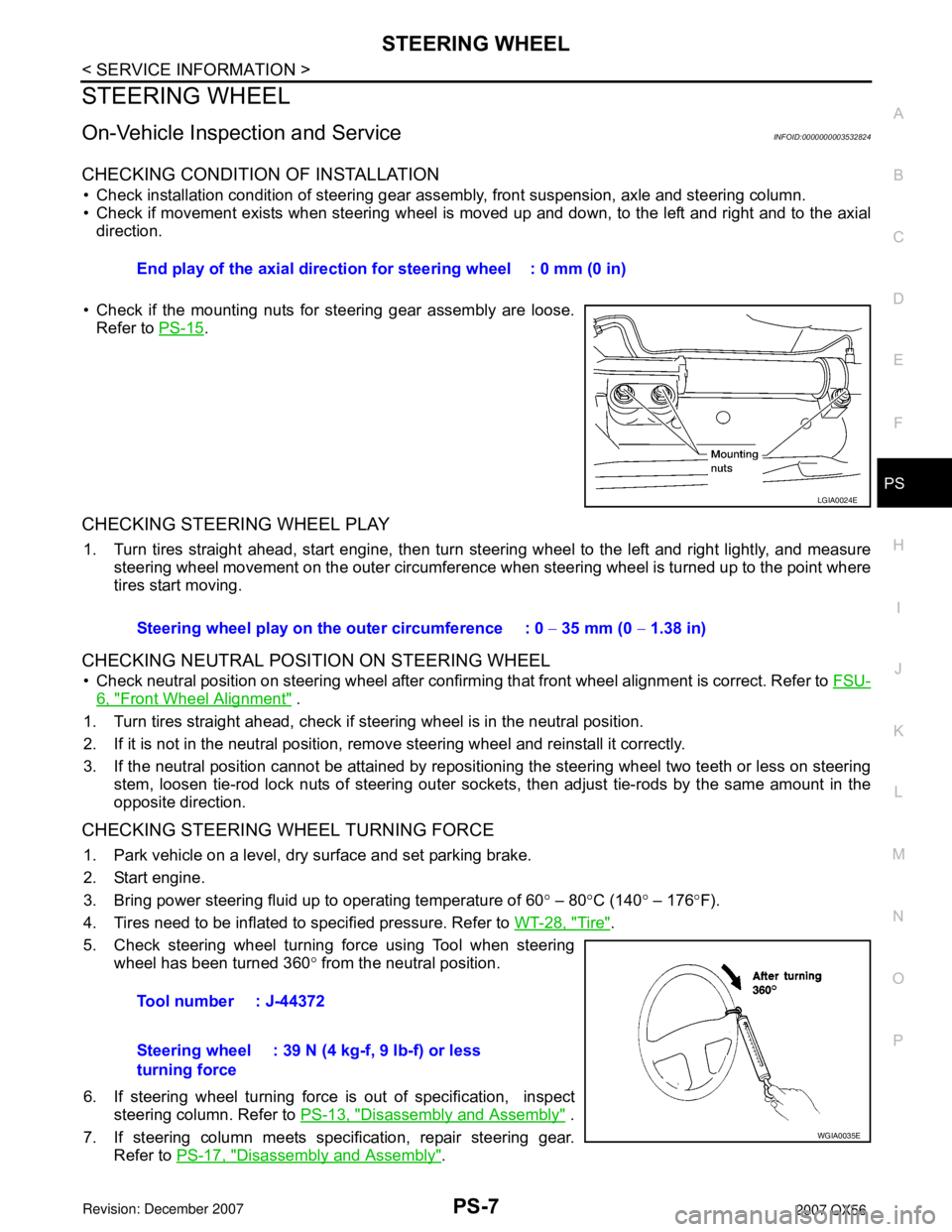
• Check if the mounting nuts for steering gear assembly are loose.
Refer to PS-15
.
CHECKING STEERING WHEEL PLAY
1. Turn tires straight ahead, start engine, then turn steering wheel to the left and right lightly, and measure
steering wheel movement on the outer circumference when steering wheel is turned up to the point where
tires start moving.
CHECKING NEUTRAL POSITION ON STEERING WHEEL
• Check neutral position on steering wheel after confirming that front wheel alignment is correct. Refer to FSU-
6, "Front Wheel Alignment" .
1. Turn tires straight ahead, check if steering wheel is in the neutral position.
2. If it is not in the neutral position, remove steering wheel and reinstall it correctly.
3. If the neutral position cannot be attained by repositioning the steering wheel two teeth or less on steering
stem, loosen tie-rod lock nuts of steering outer sockets, then adjust tie-rods by the same amount in the
opposite direction.
CHECKING STEERING WHEEL TURNING FORCE
1. Park vehicle on a level, dry surface and set parking brake.
2. Start engine.
3. Bring power steering fluid up to operating temperature of 60° – 80°C (140° – 176°F).
4. Tires need to be inflated to specified pressure. Refer to WT-28, "
Tire".
5. Check steering wheel turning force using Tool when steering
wheel has been turned 360° from the neutral position.
6. If steering wheel turning force is out of specification, inspect
steering column. Refer to PS-13, "
Disassembly and Assembly" .
7. If steering column meets specification, repair steering gear.
Refer to PS-17, "
Disassembly and Assembly". End play of the axial direction for steering wheel : 0 mm (0 in)
LGIA0024E
Steering wheel play on the outer circumference : 0 − 35 mm (0 − 1.38 in)
Tool number : J-44372
Steering wheel
turning force: 39 N (4 kg-f, 9 lb-f) or less
WGIA0035E
Page 2507 of 3061

PS-16
< SERVICE INFORMATION >
POWER STEERING GEAR AND LINKAGE
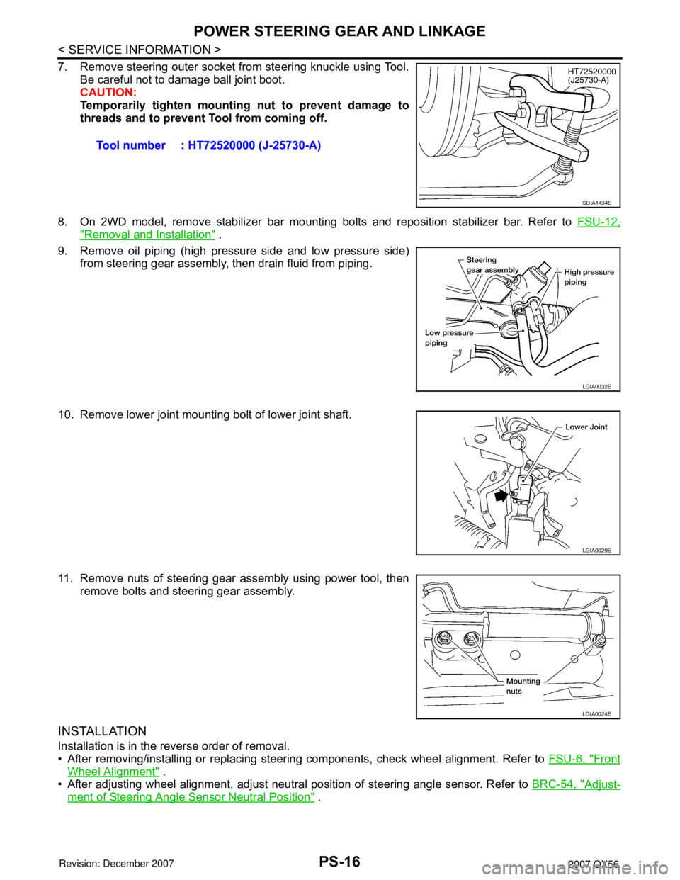
7. Remove steering outer socket from steering knuckle using Tool.
Be careful not to damage ball joint boot.
CAUTION:
Temporarily tighten mounting nut to prevent damage to
threads and to prevent Tool from coming off.
8. On 2WD model, remove stabilizer bar mounting bolts and reposition stabilizer bar. Refer to FSU-12,
"Removal and Installation" .
9. Remove oil piping (high pressure side and low pressure side)
from steering gear assembly, then drain fluid from piping.
10. Remove lower joint mounting bolt of lower joint shaft.
11. Remove nuts of steering gear assembly using power tool, then
remove bolts and steering gear assembly.
INSTALLATION
Installation is in the reverse order of removal.
• After removing/installing or replacing steering components, check wheel alignment. Refer to FSU-6, "
Front
Wheel Alignment" .
• After adjusting wheel alignment, adjust neutral position of steering angle sensor. Refer to BRC-54, "
Adjust-
ment of Steering Angle Sensor Neutral Position" . Tool number : HT72520000 (J-25730-A)
SDIA1434E
LGIA0032E
LGIA0029E
LGIA0024E
Page 2512 of 3061

POWER STEERING OIL PUMP
PS-21
< SERVICE INFORMATION >
C
D
E
F
H
I
J
K
L
MA
B
PS
N
O
P
POWER STEERING OIL PUMP
On-Vehicle Inspection and ServiceINFOID:0000000003532831
CHECKING RELIEF OIL PRESSURE
CAUTION:
Before starting work, confirm belt tension is proper.
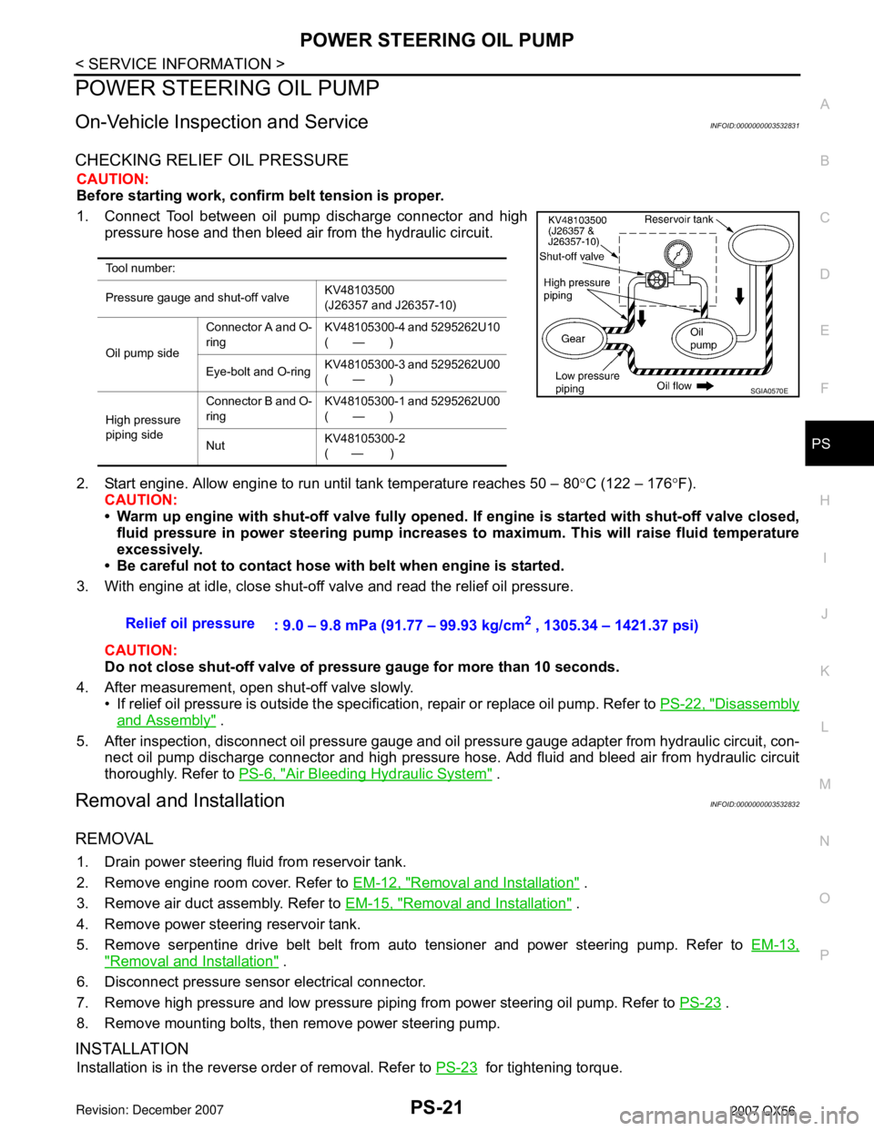
1. Connect Tool between oil pump discharge connector and high
pressure hose and then bleed air from the hydraulic circuit.
2. Start engine. Allow engine to run until tank temperature reaches 50 – 80°C (122 – 176°F).
CAUTION:
• Warm up engine with shut-off valve fully opened. If engine is started with shut-off valve closed,
fluid pressure in power steering pump increases to maximum. This will raise fluid temperature
excessively.
• Be careful not to contact hose with belt when engine is started.
3. With engine at idle, close shut-off valve and read the relief oil pressure.
CAUTION:
Do not close shut-off valve of pressure gauge for more than 10 seconds.
4. After measurement, open shut-off valve slowly.
• If relief oil pressure is outside the specification, repair or replace oil pump. Refer to PS-22, "
Disassembly
and Assembly" .
5. After inspection, disconnect oil pressure gauge and oil pressure gauge adapter from hydraulic circuit, con-
nect oil pump discharge connector and high pressure hose. Add fluid and bleed air from hydraulic circuit
thoroughly. Refer to PS-6, "
Air Bleeding Hydraulic System" .
Removal and InstallationINFOID:0000000003532832
REMOVAL
1. Drain power steering fluid from reservoir tank.
2. Remove engine room cover. Refer to EM-12, "
Removal and Installation" .
3. Remove air duct assembly. Refer to EM-15, "
Removal and Installation" .
4. Remove power steering reservoir tank.
5. Remove serpentine drive belt belt from auto tensioner and power steering pump. Refer to EM-13,
"Removal and Installation" .
6. Disconnect pressure sensor electrical connector.
7. Remove high pressure and low pressure piping from power steering oil pump. Refer to PS-23
.
8. Remove mounting bolts, then remove power steering pump.
INSTALLATION
Installation is in the reverse order of removal. Refer to PS-23 for tightening torque.
Tool number:
Pressure gauge and shut-off valveKV48103500
(J26357 and J26357-10)
Oil pump sideConnector A and O-
ringKV48105300-4 and 5295262U10
(—)
Eye-bolt and O-ringKV48105300-3 and 5295262U00
(—)
High pressure
piping sideConnector B and O-
ringKV48105300-1 and 5295262U00
(—)
NutKV48105300-2
( — )
SGIA0570E
Relief oil pressure
: 9.0 – 9.8 mPa (91.77 – 99.93 kg/cm2 , 1305.34 – 1421.37 psi)
Page 2518 of 3061

SERVICE DATA AND SPECIFICATIONS (SDS)
PS-27
< SERVICE INFORMATION >
C
D
E
F
H
I
J
K
L
MA
B
PS
N
O
P
Oil PumpINFOID:0000000003532839
Steering FluidINFOID:0000000003532840
Rack sliding forceAt the neutral point:
Range within ± 11.5 mm
(±0.453 in) from the neutral
position
(in power ON)Area average value 147 − 211 N (14.99 − 21.52 kg, 33.1 − 47.52 lb)
Allowable variation 98 N (10 kg, 22 lb) or less
Whole area (in power OFF)Peak value 294 N (30.0 kg, 66 lb) or less
Allowable variation 147 N (16 kg, 35 lb) or less Steering gear modelPR26AM
Relief oil pressure
9.0 − 9.8 mPa (91.77 − 99.93 kg/cm2, 1305.34 − 1421.37 psi)
Fluid capacity
Approx. 1.0 (1-1/8 US qt, 7/8 Imp qt)
Page 2856 of 3061

TF-34
< SERVICE INFORMATION >
TROUBLE DIAGNOSIS
Trouble Diagnosis Chart by Symptom
INFOID:0000000003532525
If 4WD warning lamp turns ON, perform self-diagnosis. Refer to TF-48, "Self-Diagnosis Procedure" .
NOTE:
• Light tight-corner braking symptom may occur depending on driving conditions in AUTO mode. This is not a
malfunction.
Symptom Condition Check item Reference page
4WD shift indicator lamp and 4LO indicator
lamp do not turn ON
(4WD shift indicator lamp and 4LO indicator
lamp check)Ignition switch: ONPower supply and ground for transfer
control unit
TF-102
Transfer shut off relay
Combination meter
4WD warning lamp does not turn ON
(4WD warning lamp check)Ignition switch: ONPower supply and ground for transfer
control unit
TF-104
Transfer shut off relay
Combination meter
4WD shift indicator lamp or 4LO indicator
lamp does not changeEngine running4WD shift switch
TF-107
Wait detection switch
Neutral-4LO switch
ATP switch
2-4WD solenoid
Transfer control device
Actuator motor
Actuator position switch
Transfer inner parts
ATP warning lamp turns ON Engine runningCAN communication line
TF-109
4WD shift switch
PNP switch signal
ATP switch
Combination meter
Transfer inner parts
4LO indicator lamp repeats flashing Engine runningWait detection switch
TF-110
Neutral-4LO switch
Transfer inner parts
4WD warning lamp flashes rapidly (2 times/
second)While drivingTransfer fluid temperature
TF-111
Tire size is different between front and
rear of vehicle
4WD warning lamp flashes slowly
(1 time/2 seconds)While drivingTire size is different between front and
rear of vehicle.
TF-112
Transfer fluid temperature
Clutch pressure switch
Heavy tight-corner braking symptom occurs
(See NOTE.)• While driving
•AUTO mode
• Steering wheel is
turned fully to either
sideCAN communication line
TF-113
4WD shift switch
Accelerator pedal position signal
Clutch pressure solenoid
Transfer inner parts
4WD system does not operate While driving4WD shift switch
TF-114
Clutch pressure switch
Transfer inner parts
Page 2857 of 3061

TROUBLE DIAGNOSIS
TF-35
< SERVICE INFORMATION >
C
E
F
G
H
I
J
K
L
MA
B
TF
N
O
P
• Heavy tight-corner braking symptom occurs when vehicle is driven in the following conditions: 4WD shift
switch is "4H" or "4LO", steering wheel is turned fully to either side.
Transfer Control Unit Input/Output Signal Reference ValueINFOID:0000000003532526
TRANSFER CONTROL UNIT INSPECTION TABLE
Specifications with CONSULT-II
Monitored item [Unit] Content Condition Display value
VHCL/S SEN·FR [km/h]
or [mph]Front wheel speedVehicle stopped 0 km/h (0 MPH)
Vehicle running
CAUTION:
Check air pressure of tire under standard condition.Approximately
equal to the indica-
tion on speedome-
ter (Inside of
±10%)
VHCL/S SEN·RR [km/h]
or [mph]Rear wheel speedVehicle stopped 0 km/h (0 MPH)
Vehicle running
CAUTION:
Check air pressure of tire under standard condition.Approximately
equal to the indica-
tion on speedome-
ter (Inside of
±10%)
ENGINE SPEED [rpm] Engine speedEngine stopped
(Engine speed: Less than 400 rpm)0 rpm
Engine running
(Engine speed: 400 rpm or more)Approximately
equal to the indica-
tion on tachometer
THRTL POS SEN [V]Accelerator pedal posi-
tion (APP) sensor signal
voltageAccelerator pedal: Release Approx. 0.5V
Accelerator pedal: Fully depressed Approx. 4.0V
FLUID TEMP SE [V]Transfer fluid tempera-
ture signal voltageTransfer fluid temperature approx. 20 - 80°C (68 - 176°F) Approx. 1.1 - 0.3V
BATTERY VOLT [V]Power supply voltage for
transfer control unitIgnition switch: ON Battery voltage
2WD SWITCH [ON/OFF]Input condition from 4WD
shift switch4WD shift switch: 2WD ON
4WD shift switch: AUTO, 4H or 4LO OFF
AUTO SWITCH [ON/
OFF]Input condition from 4WD
shift switch4WD shift switch: AUTO ON
4WD shift switch: 2WD, 4H or 4LO OFF
LOCK SWITCH [ON/
OFF]Input condition from 4WD
shift switch4WD shift switch: 4H ON
4WD shift switch: 2WD, AUTO or 4LO OFF
4L SWITCH [ON/OFF]Input condition from 4WD
shift switch4WD shift switch: 4LO ON
4WD shift switch: 2WD, AUTO or 4H OFF
N POSI SW TF [ON/
OFF]Condition of neutral-4LO
switch• Vehicle stopped
• Engine running
• A/T selector lever “N” posi-
tion
• Brake pedal depressed4WD shift switch: 2WD,
AUTO or 4HOFF
4WD shift switch: 4H to
4LO (While actuator mo-
tor is operating.)OFF → ON
4WD shift switch: 4LO to
4H (While actuator motor
is operating.)ON → OFF
4WD shift switch: 4LO ON