engine INFINITI QX56 2007 Factory Service Manual
[x] Cancel search | Manufacturer: INFINITI, Model Year: 2007, Model line: QX56, Model: INFINITI QX56 2007Pages: 3061, PDF Size: 64.56 MB
Page 1 of 3061

-1
QUICK REFERENCE INDEX
AGENERAL INFORMATIONGIGeneral Information
BENGINEEMEngine Mechanical
LUEngine Lubrication System
COEngine Cooling System
ECEngine Control System
FLFuel System
EXExhaust System
ACCAccelerator Control System
CTRANSMISSION/
TRANSAXLEATAutomatic Transmission
DDRIVELINE/AXLETFTransfer
PRPropeller Shaft
FFDFront Final Drive
RFDRear Final Drive
FAXFront Axle
RAXRear Axle
ESUSPENSIONFSUFront Suspension
RSURear Suspension
WTRoad Wheels & Tires
FBRAKESBRBrake System
PBParking Brake System
BRCBrake Control System
GSTEERINGPSPower Steering System
HRESTRAINTSSBSeat Belts
SRSSupplemental Restraint System (SRS)
IBODYBLBody, Lock & Security System
GWGlasses, Window System & Mirrors
RFRoof
EIExterior & Interior
IPInstrument Panel
SESeat
APAdjustable Pedal
JAIR CONDITIONERATCAutomatic Air Conditioner
KELECTRICALSCStarting & Charging System
LTLighting System
DIDriver Information System
WWWiper, Washer & Horn
BCSBody Control System
LANLAN System
AVAudio Visual, Navigation & Telephone System
ACSAuto Cruise Control System
PGPower Supply, Ground & Circuit Elements
LMAINTENANCEMAMaintenance
Edition: August 2006
Revision: December 2007
Publication No. SM7E-1J60U1
B
D
© 2007 NISSAN NORTH AMERICA, INC.
All rights reserved. No part of this Service Manual may be reproduced or stored in a retrieval system, or transmitted in any
form, or by any means, electronic, mechanical, photo-copying, recording or otherwise, without the prior written permission
of Nissan North America, Inc.
A
C
E
F
G
H
I
J
K
L
M
Page 4 of 3061

QUICK REFERENCE CHART: QX562007
QUICK REFERENCE CHART: QX56PFP:00000
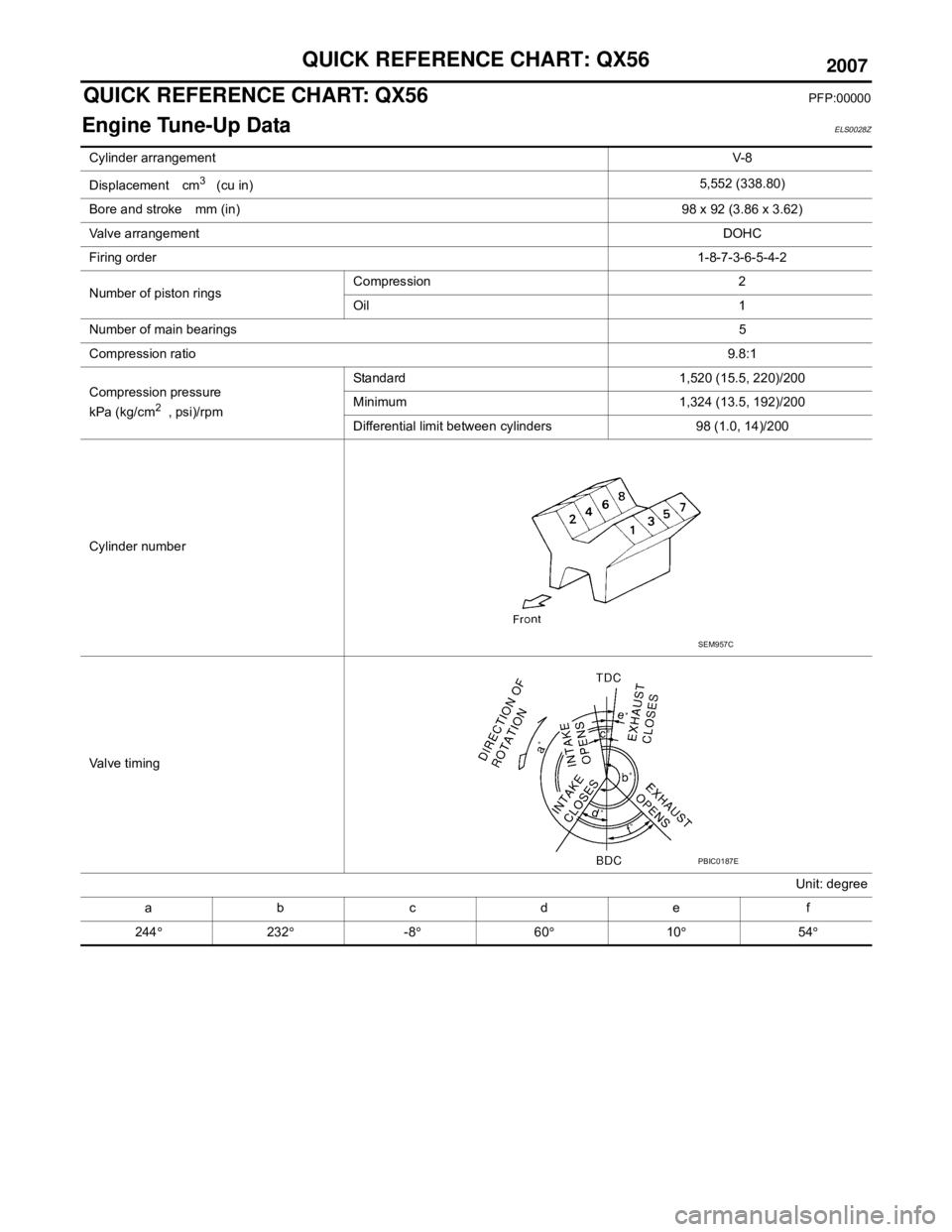
Engine Tune-Up DataELS0028Z
Cylinder arrangementV-8
Displacement cm
3 (cu in) 5,552 (338.80)
Bore and stroke mm (in) 98 x 92 (3.86 x 3.62)
Valve arrangement DOHC
Firing order 1-8-7-3-6-5-4-2
Number of piston rings Compression 2
Oil 1
Number of main bearings 5
Compression ratio 9.8:1
Compression pressure
kPa (kg/cm
2 , psi)/rpm Standard 1,520 (15.5, 220)/200
Minimum 1,324 (13.5, 192)/200
Differential limit between cylinders 98 (1.0, 14)/200
Cylinder number
Va l v e t i m i n g Unit: degree
abcde f
244 ° 232° -8° 60° 10° 54°
SEM957C
PBIC0187E
Page 5 of 3061

2007
QUICK REFERENCE CHART: QX56
Drive Belt Deflection and Tension
Spark Plug (Platinum Tipped)
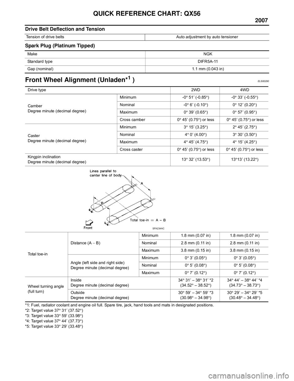
Front Wheel Alignment (Unladen*1 )ELS00290
*1: Fuel, radiator coolant and engine oil full. Spare tire, jack, hand tools and mats in designated positions.
*2: Target value 37° 31 ′ (37.52 °)
*3: Target value 33 ° 59 ′ (33.98 °)
*4: Target value 37 ° 44 ′ (37.73 °)
*5: Target value 33 ° 29 ′ (33.48 °)
Tension of drive belts Auto adjustment by auto tensioner
Make NGK
Standard type DIFR5A-11
Gap (nominal) 1.1 mm (0.043 in)
Drive type2WD 4WD
Camber
Degree minute (decimal degree) Minimum -0
° 51 ′ (-0.85 °)-0 ° 33 ′ (-0.55 °)
Nominal -0 ° 6 ′ (-0.10 °)0 ° 12 ′ (0.20 °)
Maximum 0 ° 39 ′ (0.65 °)0 ° 57 ′ (0.95 °)
Cross camber 0 ° 45 ′ (0.75 °) or less 0 ° 45 ′ (0.75 °) or less
Caster
Degree minute (decimal degree) Minimum 3
° 15 ′ (3.25 °)2 ° 45 ′ (2.75 °)
Nominal 4 ° 0 ′ (4.00 °)3 ° 30 ′ (3.50 °)
Maximum 4 ° 45 ′ (4.75 °)4 ° 15 ′ (4.25 °)
Cross caster 0 ° 45 ′ (0.75 °) or less 0 ° 45 ′ (0.75 °) or less
Kingpin inclination
Degree minute (decimal degree) 13
° 32 ′ (13.53 °)13 °13 ′ (13.22 °)
Total toe-in Distance (A
− B) Minimum 1.8 mm (0.07 in) 1.8 mm (0.07 in)
Nominal 2.8 mm (0.11 in) 2.8 mm (0.11 in)
Maximum 3.8 mm (0.15 in) 3.8 mm (0.15 in)
Angle (left side and right side)
Degree minute (decimal degree) Minimum 0
° 3 ′ (0.05 °)0 ° 3 ′ (0.05 °)
Nominal 0 ° 5 ′ (0.08 °)0 ° 5 ′ (0.08 °)
Maximum 0 ° 7 ′ (0.12 °)0 ° 7 ′ (0.12 °)
Wheel turning angle
(full turn) Inside
Degree minute (decimal degree)
34
° 31 ′ – 38 ° 31 ′ *2
(34.52 ° – 38.52 °) 34
° 44 ′ – 38 ° 44 ′ *4
(34.73 ° – 38.73 °)
Outside
Degree minute (decimal degree) 30
° 59 ′ – 34 ° 59 ′ *3
(30.98 ° – 34.98 °) 30
° 29 ′ – 34 ° 29 ′ *5
(30.48 ° – 34.48 °)
SFA234AC
Page 7 of 3061

2007
QUICK REFERENCE CHART: QX56
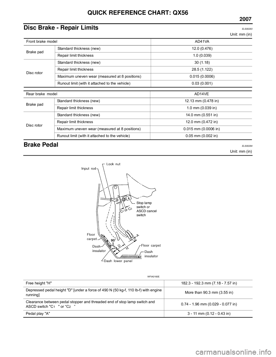
Disc Brake - Repair LimitsELS00293
Unit: mm (in)
Brake PedalELS00294
Unit: mm (in)
Front brake model
AD41VA
Brake pad Standard thickness (new) 12.0 (0.476)
Repair limit thickness 1.0 (0.039)
Disc rotor Standard thickness (new) 30 (1.18)
Repair limit thickness 28.5 (1.122)
Maximum uneven wear (measured at 8 positions) 0.015 (0.0006)
Runout limit (with it attached to the vehicle) 0.03 (0.001)
Rear brake model
AD14VE
Brake pad Standard thickness (new) 12.13 mm (0.478 in)
Repair limit thickness 1.0 mm (0.039 in)
Disc rotor Standard thickness (new) 14.0 mm (0.551 in)
Repair limit thickness 12.0 mm (0.472 in)
Maximum uneven wear (measured at 8 positions) 0.015 mm (0.0006 in)
Runout limit (with it attached to the vehicle) 0.05 mm (0.002 in)
Free height "H"
182.3 - 192.3 mm (7.18 - 7.57 in)
Depressed pedal height "D" [under a force of 490 N (50 kg-f, 110 lb-f) with engine
running] More than 90.3 mm (3.55 in)
Clearance between pedal stopper and threaded end of stop lamp switch and
ASCD switch "C
1 " or “C2 ” 0.74 - 1.96 mm (0.029 - 0.077 in)
Pedal play "A" 3 - 11 mm (0.12 - 0.43 in)
WFIA0160E
Page 8 of 3061

QUICK REFERENCE CHART: QX56
2007
Refill CapacitiesELS00295
DescriptionCapacity (Approximate)
Metric US measure Imp measure
Fuel 105.8 28 gal 23 1/4 gal
Engine oil
(drain and refill) With oil filter change
6.2 6 1/2 qt 5 1/2 qt
Without oil filter change 5.9 6 1/4 qt 5 1/4 qt
Dry engine (engine overhaul) 7.6 8 qt 6 3/4 qt
Cooling system With reservoir at MAX level 14.4 3 3/4 gal 3 1/8 gal
Automatic transmission fluid (ATF) 10.6 11 1/4 qt 9 3/8 qt
Rear final drive oil 1.75 3 3/4 pt 3 1/8 pt
Transfer fluid 3.0 3 1/8 qt 2 5/8 qt
Front final drive oil 1.6 3 3/8 pt 2 7/8 pt
Power steering fluid (PSF) 1.0 2 1/8 pt 1 3/4 pt
Windshield washer fluid 4.5 1 1/4 gal 1 gal
Air conditioning system refrigerant 1.08 ± 0.05 kg 2.38 ± 0.11 lb 2.38 ± 0.11 lb
Air conditioning system lubricants 290 m9.8 fl oz 10.2 fl oz
Page 9 of 3061

ACC-1
ENGINE
C
D
E
F
G
H
I
J
K
L
M
SECTION ACC
A
ACC
N
O
P
CONTENTS
ACCELERATOR CONTROL SYSTEM
SERVICE INFORMATION ............................2
PRECAUTIONS ...................................................2
Precaution for Supplemental Restraint System
(SRS) "AIR BAG" and "SEAT BELT PRE-TEN-
SIONER" ...................................................................
2
ACCELERATOR CONTROL SYSTEM ..............3
Removal and Installation ..........................................3
SERVICE DATA AND SPECIFICATIONS
(SDS) ..................................................................
5
Accelerator Control ...................................................5
Page 23 of 3061
![INFINITI QX56 2007 Factory Service Manual ACS-10
< SERVICE INFORMATION >[ICC]
ACTION TEST
1. Start the engine. Then, check that the following operations are
performed correctly.
2. Vehicle-to-vehicle distance control mode is displayed when O INFINITI QX56 2007 Factory Service Manual ACS-10
< SERVICE INFORMATION >[ICC]
ACTION TEST
1. Start the engine. Then, check that the following operations are
performed correctly.
2. Vehicle-to-vehicle distance control mode is displayed when O](/img/42/57029/w960_57029-22.png)
ACS-10
< SERVICE INFORMATION >[ICC]
ACTION TEST
1. Start the engine. Then, check that the following operations are
performed correctly.
2. Vehicle-to-vehicle distance control mode is displayed when ON/
OFF switch is pressed ON. Vehicle-to-vehicle distance control
mode goes off when ON/OFF switch is turned to OFF.
3. Turn off the ignition switch while ON/OFF switch is ON. Turn the
ignition switch back to ON and confirm that CRUISE lamp and
ICC system display are OFF.
CHECK FOR ACCEL/RES, COAST/SET, CANCEL SWITCHES
1. Check if ACCEL/RES, COAST/SET, CANCEL switches operate smoothly.
2. Check if switch buttons rebound as the buttons are released.
CHECK FOR DISTANCE SWITCH
1. Start the engine.
2. Press the ON/OFF switch for less than 1.5 seconds.
3. Press the DISTANCE switch.
4. Check if the set distance indicator changes display in order of:
(long)→(middle)→(short).
NOTE:
The set distance indicator shows long immediately after the engine starts.
CONVENTIONAL (FIXED SPEED) CRUISE CONTROL MODE
SET CHECKING
1. Press the ON/OFF switch for more than 1.5 seconds.
2. Drive the vehicle between 40 km/h (25 MPH) and 144 km/h (89 MPH).
3. Push the COAST/SET switch.
4. Confirm that the desired speed is set when the COAST/SET switch is released.
NOTE:
• ICC system display in the combination meter shows nothing.
CHECK FOR INCREASE OF THE CRUISING SPEED
1. Set the conventional (fixed speed) cruise control mode at desired speed.
2. Check if the set speed increases by 1.6 km/h (1 MPH) as ACCEL/RES switch is pushed.
NOTE:
• If the ACCEL/RES switch is held, the vehicle speed increases until the switch is released.
• The maximum set speed is 144 km/h (89 MPH).
WKIA1978E
SKIA6178E
Page 24 of 3061
![INFINITI QX56 2007 Factory Service Manual ACTION TEST
ACS-11
< SERVICE INFORMATION >[ICC]
C
D
E
F
G
H
I
J
L
MA
B
ACS
N
O
P CHECK FOR DECREASE OF THE CRUISING SPEED
1. Set the conventional (fixed speed) cruise control mode at desired speed.
2. INFINITI QX56 2007 Factory Service Manual ACTION TEST
ACS-11
< SERVICE INFORMATION >[ICC]
C
D
E
F
G
H
I
J
L
MA
B
ACS
N
O
P CHECK FOR DECREASE OF THE CRUISING SPEED
1. Set the conventional (fixed speed) cruise control mode at desired speed.
2.](/img/42/57029/w960_57029-23.png)
ACTION TEST
ACS-11
< SERVICE INFORMATION >[ICC]
C
D
E
F
G
H
I
J
L
MA
B
ACS
N
O
P CHECK FOR DECREASE OF THE CRUISING SPEED
1. Set the conventional (fixed speed) cruise control mode at desired speed.
2. Check if the set speed decreases by 1.6 km/h (1 MPH) as COAST/SET switch is pushed.
NOTE:
• Conventional (fixed speed) cruise control mode is automatically turned off when the driving speed lowers to
32 km/h (20 MPH).
• The lowest set speed is 40 km/h (25 MPH).
CHECK FOR THE CANCELLATION OF CONVENTIONAL (FIXED SPEED) CRUISE CONTROL MODE (NORMAL
DRIVING CONDITION) IN THE FOLLOWING CASES:
Refer to "CHECK FOR THE CANCELLATION OF VEHICLE-TO-VEHICLE DISTANCE CONTROL MODE
(NORMAL DRIVING CONDITION) IN THE FOLLOWING CASES:" .
CHECK FOR RESTORING THE SPEED THAT IS SET BY CONVENTIONAL (FIXED SPEED) CRUISE CONTROL
MODE BEFORE ICC CANCELLATION
Refer to "CHECK FOR RESTORING THE SPEED THAT IS SET BY VEHICLE-TO-VEHICLE DISTANCE
CONTROL MODE BEFORE CANCELLATION" .
CHECK ON/OFF SWITCH OPERATION
1. Start the engine. Then, check that the following operations are
performed correctly.
2. CRUISE lamp (green) illuminates and ICC system indicator
goes off when ON/OFF switch is pressed ON for more than 1.5
seconds. The CRUISE lamp goes off when ON/OFF switch is
turned to OFF.
3. Turn off the ignition switch while ON/OFF switch is ON. Turn the
ignition switch back to ON and confirm that CRUISE lamp is
OFF.
CHECK FOR ACCEL/RES, COAST/SET, CANCEL SWITCHES
1. Check if ACCEL/RES, COAST/SET, CANCEL switches operate smoothly.
2. Check if switch buttons rebound as the buttons are released.
WKIA2038E
Page 25 of 3061
![INFINITI QX56 2007 Factory Service Manual ACS-12
< SERVICE INFORMATION >[ICC]
LASER BEAM AIMING ADJUSTMENT
LASER BEAM AIMING ADJUSTMENT
Outline of Laser Beam Aiming Adjustment ProcedureINFOID:0000000003533782
CAUTION:
• The laser beam aimin INFINITI QX56 2007 Factory Service Manual ACS-12
< SERVICE INFORMATION >[ICC]
LASER BEAM AIMING ADJUSTMENT
LASER BEAM AIMING ADJUSTMENT
Outline of Laser Beam Aiming Adjustment ProcedureINFOID:0000000003533782
CAUTION:
• The laser beam aimin](/img/42/57029/w960_57029-24.png)
ACS-12
< SERVICE INFORMATION >[ICC]
LASER BEAM AIMING ADJUSTMENT
LASER BEAM AIMING ADJUSTMENT
Outline of Laser Beam Aiming Adjustment ProcedureINFOID:0000000003533782
CAUTION:
• The laser beam aiming adjustment cannot be performed without CONSULT-II.
• The laser beam aiming adjustment must be performed every time the ICC sensor is removed,
installed or has been moved as a result of a collision.
1. Prepare the vehicle and the work area.
2. Set up the ICC target board. For details, refer to Technical Service Bulletin.
3. Adjust the sensor following the procedure on CONSULT-II.
4. Check system operation after the adjustment.
PreparationINFOID:0000000003533783
• Place the vehicle on level ground. Shift the transmission into "P" position and release the parking brake.
• Adjust the tire pressure to the specified value.
• See that there is no load in the vehicle. Coolant, engine oil and fuel should be filled to correct level.
• Check that the vehicle suspension has been adjusted to the standard height by the load leveling rear air sus-
pension system. Refer to RSU-10, "
Basic Inspection" .
• Clean the sensor with a soft cloth.
Setting up the ICC Target BoardINFOID:0000000003533784
CAUTION:
Accuracy in setting up the ICC target board is essential for the laser beam aiming adjustment. For
details, refer to Technical Service Bulletin.
ADJUSTING HEIGHT OF THE TARGET
1. Attach a triangle scale as shown.Tool number : KV99110100 (J-45718)
LKIA0632E
WKIA1849E
Page 28 of 3061
![INFINITI QX56 2007 Factory Service Manual LASER BEAM AIMING ADJUSTMENT
ACS-15
< SERVICE INFORMATION >[ICC]
C
D
E
F
G
H
I
J
L
MA
B
ACS
N
O
P
3. Start the engine, wait for at least 10 sec., and touch “START
(NISSAN BASED VHCL)”.
4. Touch � INFINITI QX56 2007 Factory Service Manual LASER BEAM AIMING ADJUSTMENT
ACS-15
< SERVICE INFORMATION >[ICC]
C
D
E
F
G
H
I
J
L
MA
B
ACS
N
O
P
3. Start the engine, wait for at least 10 sec., and touch “START
(NISSAN BASED VHCL)”.
4. Touch �](/img/42/57029/w960_57029-27.png)
LASER BEAM AIMING ADJUSTMENT
ACS-15
< SERVICE INFORMATION >[ICC]
C
D
E
F
G
H
I
J
L
MA
B
ACS
N
O
P
3. Start the engine, wait for at least 10 sec., and touch “START
(NISSAN BASED VHCL)”.
4. Touch “ICC”.
If “ICC” is not indicated, go to GI-38, "
CONSULT-II Data Link
Connector (DLC) Circuit" .
5. Touch “WORK SUPPORT”.
6. Touch “LASER BEAM ADJUST”.
7. Touch “START”.
CAUTION:
If the adjustment screen does not appear on CONSULT-II 10
sec. after touching “LASER BEAM ADJUST” screen, the fol-
lowing causes may be considered:
• Target is not set accurately.
• There is not enough space beside the target.
• Deformation of vehicle or inappropriate installation of
sensor. Sensor may be installed out of the adjustable
range.
• The area is not suitable for the adjustment work.
• ICC sensor is not clean.
BCIA0029E
BCIA0030E
BCIA0031E
SKIA6191E
WKIA2675E