tow INFINITI QX56 2007 Factory User Guide
[x] Cancel search | Manufacturer: INFINITI, Model Year: 2007, Model line: QX56, Model: INFINITI QX56 2007Pages: 3061, PDF Size: 64.56 MB
Page 368 of 3061

AT-298
< SERVICE INFORMATION >
SERVICE DATA AND SPECIFICATIONS (SDS)
SERVICE DATA AND SPECIFICATIONS (SDS)
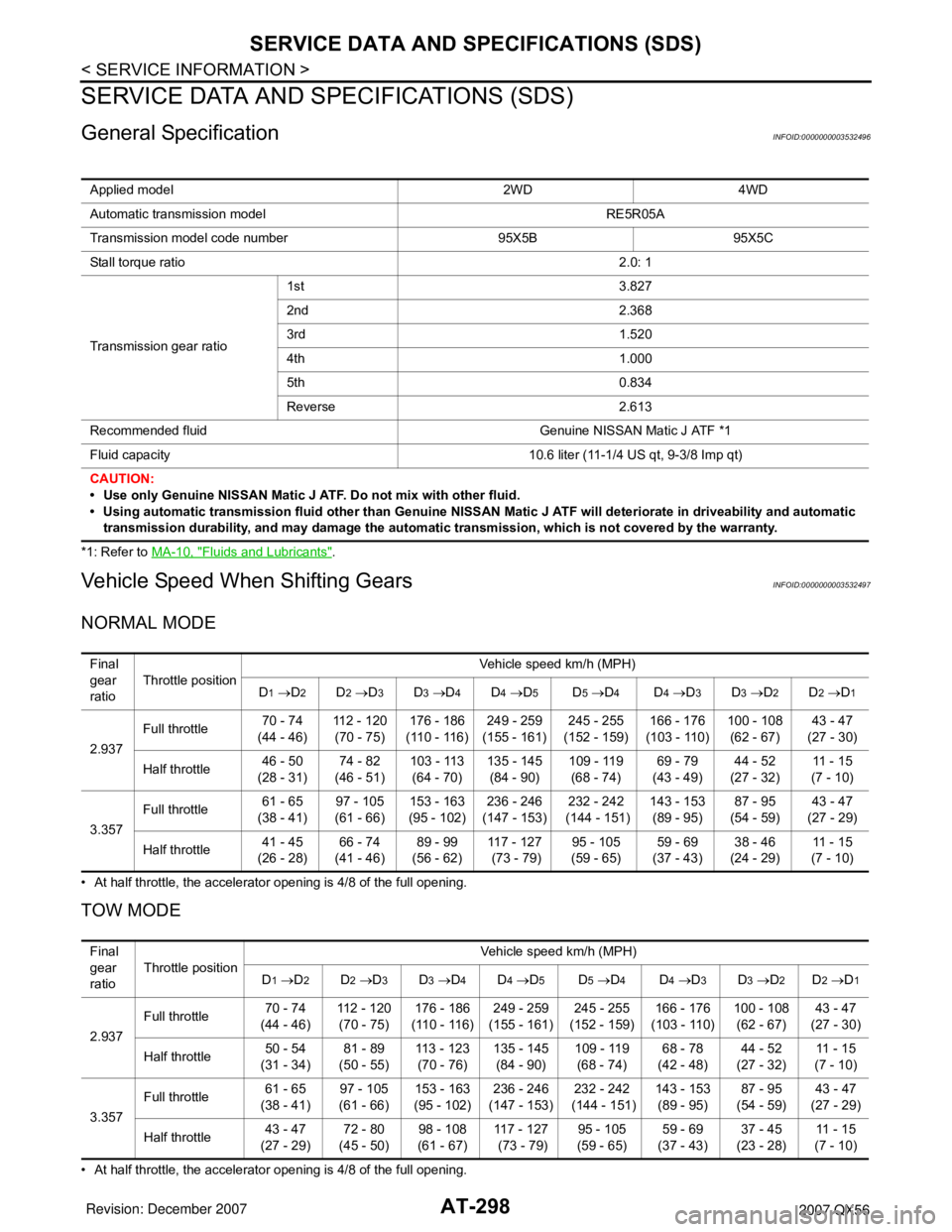
General SpecificationINFOID:0000000003532496
*1: Refer to MA-10, "Fluids and Lubricants".
Vehicle Speed When Shifting GearsINFOID:0000000003532497
NORMAL MODE
• At half throttle, the accelerator opening is 4/8 of the full opening.
TOW MODE
• At half throttle, the accelerator opening is 4/8 of the full opening.Applied model 2WD 4WD
Automatic transmission model RE5R05A
Transmission model code number 95X5B 95X5C
Stall torque ratio2.0: 1
Transmission gear ratio1st 3.827
2nd 2.368
3rd 1.520
4th 1.000
5th 0.834
Reverse 2.613
Recommended fluid Genuine NISSAN Matic J ATF *1
Fluid capacity 10.6 liter (11-1/4 US qt, 9-3/8 Imp qt)
CAUTION:
• Use only Genuine NISSAN Matic J ATF. Do not mix with other fluid.
• Using automatic transmission fluid other than Genuine NISSAN Matic J ATF will deteriorate in driveability and automatic
transmission durability, and may damage the automatic transmission, which is not covered by the warranty.
Final
gear
ratioThrottle positionVehicle speed km/h (MPH)
D
1 →D2D2 →D3D3 →D4D4 →D5D5 →D4D4 →D3D3 →D2D2 →D1
2.937Full throttle 70 - 74
(44 - 46)112 - 120
(70 - 75)176 - 186
(110 - 116)249 - 259
(155 - 161)245 - 255
(152 - 159)166 - 176
(103 - 110)100 - 108
(62 - 67)43 - 47
(27 - 30)
Half throttle 46 - 50
(28 - 31)74 - 82
(46 - 51)103 - 113
(64 - 70)135 - 145
(84 - 90)109 - 119
(68 - 74)69 - 79
(43 - 49)44 - 52
(27 - 32)11 - 1 5
(7 - 10)
3.357Full throttle 61 - 65
(38 - 41)97 - 105
(61 - 66)153 - 163
(95 - 102)236 - 246
(147 - 153)232 - 242
(144 - 151)143 - 153
(89 - 95)87 - 95
(54 - 59)43 - 47
(27 - 29)
Half throttle 41 - 45
(26 - 28)66 - 74
(41 - 46)89 - 99
(56 - 62)117 - 127
(73 - 79)95 - 105
(59 - 65)59 - 69
(37 - 43)38 - 46
(24 - 29)11 - 1 5
(7 - 10)
Final
gear
ratioThrottle positionVehicle speed km/h (MPH)
D
1 →D2D2 →D3D3 →D4D4 →D5D5 →D4D4 →D3D3 →D2D2 →D1
2.937Full throttle 70 - 74
(44 - 46)112 - 120
(70 - 75)176 - 186
(110 - 116)249 - 259
(155 - 161)245 - 255
(152 - 159)166 - 176
(103 - 110)100 - 108
(62 - 67)43 - 47
(27 - 30)
Half throttle 50 - 54
(31 - 34)81 - 89
(50 - 55)113 - 123
(70 - 76)135 - 145
(84 - 90)109 - 119
(68 - 74)68 - 78
(42 - 48)44 - 52
(27 - 32)11 - 1 5
(7 - 10)
3.357Full throttle 61 - 65
(38 - 41)97 - 105
(61 - 66)153 - 163
(95 - 102)236 - 246
(147 - 153)232 - 242
(144 - 151)143 - 153
(89 - 95)87 - 95
(54 - 59)43 - 47
(27 - 29)
Half throttle 43 - 47
(27 - 29)72 - 80
(45 - 50)98 - 108
(61 - 67)117 - 127
(73 - 79)95 - 105
(59 - 65)59 - 69
(37 - 43)37 - 45
(23 - 28)11 - 1 5
(7 - 10)
Page 677 of 3061

NAVIGATION SYSTEM
AV-137
< SERVICE INFORMATION >
C
D
E
F
G
H
I
J
L
MA
B
AV
N
O
P
Correction = A/B
A: Distance shown on the screen
B: Actual distance
YES or NO
YES >> • If adjustment is insufficient, perform adjustment again.
• If any error is found in the map, please contact map data supplier. Refer to Navigation System
Owner's Manual for contact information.
• Replace NAVI control unit. Refer to AV-145, "
Removal and Installation".
NO >> Limit of the location detection capacity of the navigation system.
Example of Symptom Judged Not MalfunctionINFOID:0000000003533768
BASIC OPERATION
VEHICLE MARK
Symptom Cause Remedy
No image is shown. Display brightness adjustment is set fully to DARK
side.Adjust the display brightness.
No guide sound is heard.
Audio guide volume is too low or
too high.Volume control is set to OFF, MIN or MAX. Adjust the audio guide volume.
Audio guidance is not available while the vehicle is
driving on a dark pink route.System is not malfunctioning.
Screen is too dark.
Motion of the image is too slow.Temperature inside the vehicle is low. Wait until the temperature inside the vehicle
reaches the proper temperature.
Small black or bright spots appear
on the screen.Symptom peculiar to a liquid crystal display (dis-
play unit).System is not malfunction.
Symptom Cause Remedy
Map screen and BIRDVIEW™
Name of the place varies with the
screen.Some thinning of the character data is done to pre-
vent the display becoming to complex. In some
cases and in some locations, the display contents
may differ.
The same place name, street name, etc. may not
be displayed every time on account of the data
processing.System is not malfunctioning.
Vehicle mark is not positioned cor-
rectly.Vehicle is transferred by ferry or by towing after its
ignition switch is turned to OFF.Drive the vehicle for a while in the GPS sat-
ellite signal receiving condition.
Screen will not switch to nighttime
mode after the lighting switch is
turned ON.The daytime screen is selected by the “SWITCH
SCREENS” when the last time the screen dim-
ming setting is done.
Switching between daytime/nighttime screen may
be inhibited by the automatic illumination adjust-
ment function.Perform screen dimming and select the
nighttime screen by “SWITCH SCREENS”.
Map screen will not scroll in accor-
dance with the vehicle travel.Current location is not displayed. Press “MAP” button to display the current lo-
cation.
Vehicle mark will not be shown. Current location is not displayed. Press “MAP” button to display the current lo-
cation.
Accuracy indicator (GPS satellite
mark) on the map screen stays
gray.GPS satellite signal is intercepted because the ve-
hicle is in or behind a building.Move the vehicle out to an open space.
GPS satellite signal cannot be received because
an obstacle is placed on top of the instrument pan-
el.Do not place anything in the center on top of
the display.
GPS satellites are not visible from current location. Wait until GPS satellites are visible by mov-
ing the vehicle.
Page 683 of 3061

NAVIGATION SYSTEM
AV-143
< SERVICE INFORMATION >
C
D
E
F
G
H
I
J
L
MA
B
AV
N
O
P
CURRENT-LOCATION MARK SHOWS A POSITION WHICH IS COMPLETELY WRONG
In the following cases, the current-location mark may appear on completely different position in the map
depending on the GPS satellite signal receiving conditions. In this case, perform location correction and direc-
tion correction.
• When location correction has not been done
- If the receiving conditions of the GPS satellite signal is poor, or if the current-location mark becomes out of
place, it may move to a completely different location and not come back if location correction is not done.
The position will be corrected if the GPS signal can be received.
• When the vehicle has traveled by ferry, or when the vehicle has been towed
- Because calculation of the current location cannot be done when travelling with the ignition OFF, for exam-
ple when traveling by ferry or when being towed, the location before travel is displayed. If the precise loca-
tion can be detected with GPS, the location will be corrected.
CURRENT-LOCATION MARK JUMPS
In the following cases, the current-location mark may appear to jump as a result of automatic correction of the
current location.
• When map-matching has been done
- If the current location and the current-location mark are different when map-matching is done, the current-
location mark may seem to jump. At this time, the location may be “corrected” to the wrong road or to a loca-
tion which is not on a road.
• When GPS location correction has been done
- If the current location and the current-location mark are different when the location is corrected using GPS
measurements, the current-location mark may seem to jump. At this time, the location may be “corrected” to
a location which is not on a road.
CURRENT-LOCATION MARK IS IN A RIVER OR SEA
The navigation system moves the current-location mark with no distinction between land and rivers or sea. If
the location mark is somehow out of place, it may appear that the vehicle is driving in a river or the sea.
WHEN DRIVING ON SAME ROAD, SOMETIMES CURRENT-LOCATION MARK IS IN RIGHT
Precautions
for drivingJust after the engine is startedIf the vehicle is driven just after the engine
is started when the gyroscope (angular
speed sensor) correction is not completed,
the vehicle can lose its direction and may
have deviated from the correct location.Wait for a short while before
driving after starting the engine.
Continuous driving without stopping When driving long distances without stop-
ping, direction errors may accumulate, and
the current-location mark may deviate from
the correct road.Stop and adjust the orientation.
Abusive driving Spinning the wheels or engaging in other
kinds of abusive driving may result in the
system being unable perform correct detec-
tion, and may cause the vehicle mark to de-
viate from the correct road.If after travelling about 10 km (6
miles) the correct location has
not been restored, perform lo-
cation correction and, if neces-
sary, direction correction.
How to cor-
rect locationPosition correction accuracy
If the accuracy of location settings is poor,
accuracy may be reduced when the correct
road cannot be found, particularly in places
where there are many roads.Enter in the road displayed on
the screen with an accuracy of
approx. 1mm.
Caution: Whenever possible,
use detailed map for the correc-
tion.
Direction when location is corrected
If the accuracy of location settings during
correction is poor, accuracy may be re-
duced afterwards.Perform direction correction. Cause (condition) –: While driving ooo: Display Driving condition Remarks (correction, etc.)
SEL701V
SEL702V
Page 694 of 3061

BCM (BODY CONTROL MODULE)
BCS-7
< SERVICE INFORMATION >
C
D
E
F
G
H
I
J
L
MA
B
BCS
N
O
P
CAN Communication System DescriptionINFOID:0000000003533597
Refer to LAN-4.
Headlamp Combination switch IPDM E/R
Tail lamp Combination switch IPDM E/R
Front fog lamp Combination switch IPDM E/R
Turn signal lamp Combination switch• Turn signal lamp
• Combination meter
Hazard lamp Hazard switch• Turn signal lamp
• Combination meter
Room lamp timer• Key switch
• Remote keyless entry receiver (keyfob)
• Main power window and door lock/unlock switch
• Front door lock assembly LH (key cylinder switch)
• All door switchesInterior room lamp
Key warning chime• Key switch
• Front door switch LHCombination meter (warning buzz-
er)
Light warning chime• Combination switch
• Key switch
• Front door switch LHCombination meter (warning buzz-
er)
Vehicle-speed-sensing intermittent wip-
er• Combination switch
• Combination meterIPDM E/R
Rear window defogger Rear window defogger switch IPDM E/R
Air conditioner switch signal Front air control ECM
Blower fan switch signal Front air control ECM
Low tire pressure warning system Remote keyless entry receiver• Combination meter
• Display control unit
Trailer tow (if equipped) Combination switch Trailer turn signal relays
Vehicle security system• Remote keyless entry receiver (keyfob)
• Main power window and door lock/unlock switch
• Power window and door lock/unlock switch RH
• Front door lock assembly LH (key cylinder switch)
• All door switches
• Back door latch (door ajar switch)• IPDM E/R
• Security indicator lamp System Input Output
Page 822 of 3061

FRONT DOOR LOCK
BL-111
< SERVICE INFORMATION >
C
D
E
F
G
H
J
K
L
MA
B
BL
N
O
P
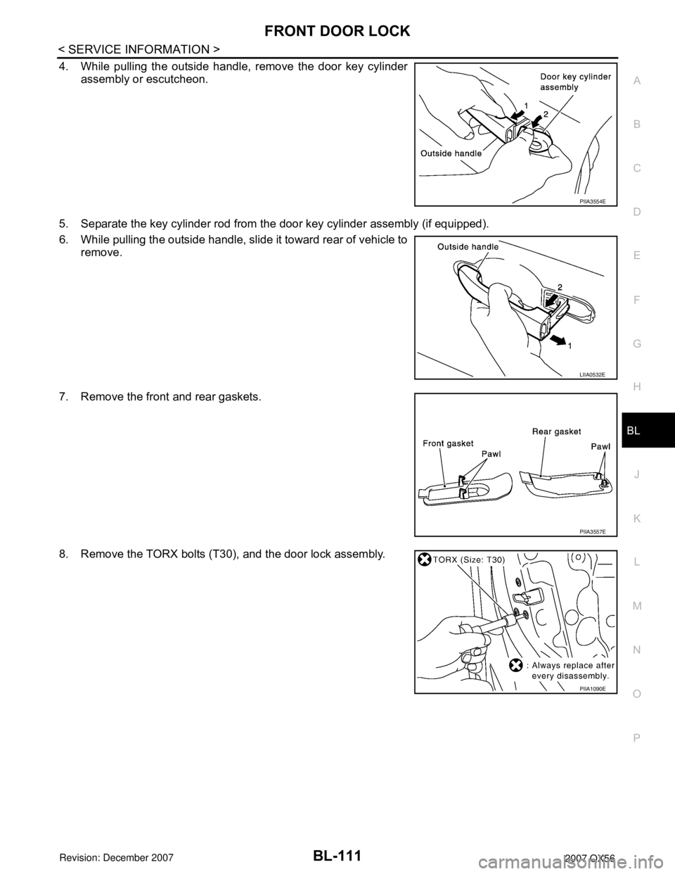
4. While pulling the outside handle, remove the door key cylinder
assembly or escutcheon.
5. Separate the key cylinder rod from the door key cylinder assembly (if equipped).
6. While pulling the outside handle, slide it toward rear of vehicle to
remove.
7. Remove the front and rear gaskets.
8. Remove the TORX bolts (T30), and the door lock assembly.
PIIA3554E
LIIA0532E
PIIA3557E
PIIA1090E
Page 823 of 3061

BL-112
< SERVICE INFORMATION >
FRONT DOOR LOCK
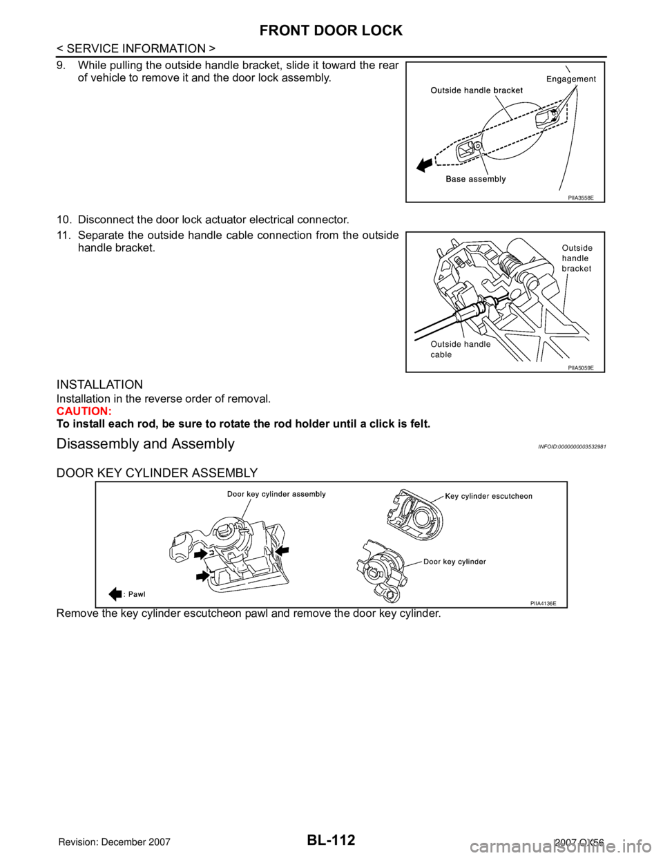
9. While pulling the outside handle bracket, slide it toward the rear
of vehicle to remove it and the door lock assembly.
10. Disconnect the door lock actuator electrical connector.
11. Separate the outside handle cable connection from the outside
handle bracket.
INSTALLATION
Installation in the reverse order of removal.
CAUTION:
To install each rod, be sure to rotate the rod holder until a click is felt.
Disassembly and AssemblyINFOID:0000000003532981
DOOR KEY CYLINDER ASSEMBLY
Remove the key cylinder escutcheon pawl and remove the door key cylinder.
PIIA3558E
PIIA5059E
PIIA4136E
Page 932 of 3061
![INFINITI QX56 2007 Factory User Guide BRC-4
< SERVICE INFORMATION >[VDC/TCS/ABS]
PRECAUTIONS
• If YES, GO TO 2.
• If NO, GO TO 5.
2. Is there any indication other than indications relating to CAN communication system in the self-diagn INFINITI QX56 2007 Factory User Guide BRC-4
< SERVICE INFORMATION >[VDC/TCS/ABS]
PRECAUTIONS
• If YES, GO TO 2.
• If NO, GO TO 5.
2. Is there any indication other than indications relating to CAN communication system in the self-diagn](/img/42/57029/w960_57029-931.png)
BRC-4
< SERVICE INFORMATION >[VDC/TCS/ABS]
PRECAUTIONS
• If YES, GO TO 2.
• If NO, GO TO 5.
2. Is there any indication other than indications relating to CAN communication system in the self-diagnosis
results?
• If YES, GO TO 3.
• If NO, GO TO 4.
3. Based on self-diagnosis results unrelated to CAN communication, carry out the inspection.
4. Malfunctions may be detected in self-diagnosis depending on control units carrying out CAN communica-
tion. Therefor, erase the self-diagnosis results.
5. Diagnose CAN communication system. Refer to LAN-7
.
Precaution for Brake ControlINFOID:0000000003532764
• During ABS operation, the brake pedal may vibrate lightly and a mechanical noise may be heard. This is
normal.
• Just after starting vehicle, the brake pedal may vibrate or a motor operating noise may be heard from engine
compartment. This is a normal status of operation check.
• Stopping distance may be longer than that of vehicles without ABS when vehicle drives on rough, gravel, or
snow-covered (fresh, deep snow) roads.
• When an error is indicated by ABS or another warning lamp, collect all necessary information from customer
(what symptoms are present under what conditions) and check for simple causes before starting diagnosis.
Besides electrical system inspection, check booster operation, brake fluid level, and fluid leaks.
• If incorrect tire sizes or types are installed on the vehicle or brake pads are not Genuine NISSAN parts, stop-
ping distance or steering stability may deteriorate.
• If there is a radio, antenna or related wiring near control module, ABS function may have a malfunction or
error.
• If aftermarket parts (car stereo, CD player, etc.) have been installed, check for incidents such as harness
pinches, open circuits or improper wiring.
• If the following components are replaced with non-genuine components or modified, the VDC OFF indicator
lamp and SLIP indicator lamp may turn on or the VDC system may not operate properly. Components
related to suspension (shock absorbers, struts, springs, bushings, etc.), tires, wheels (exclude specified
size), components related to brake system (pads, rotors, calipers, etc.), components related to engine (muf-
fler, ECM, etc.), components related to body reinforcement (roll bar, tower bar, etc.).
• Driving with broken or excessively worn suspension components, tires or brake system components may
cause the VDC OFF indicator lamp and the SLIP indicator lamp to turn on, and the VDC system may not
operate properly.
• When the TCS or VDC is activated by sudden acceleration or sudden turn, some noise may occur. The
noise is a result of the normal operation of the TCS and VDC.
• When driving on roads which have extreme slopes (such as mountainous roads) or high banks (such as
sharp curves on a freeway), the VDC may not operate normally, or the VDC warning lamp and the SLIP indi-
cator lamp may turn on. This is not a problem if normal operation can be resumed after restarting the engine.
• Sudden turns (such as spin turns, acceleration turns), drifting, etc. with VDC turned off may cause the yaw
rate/side/decel G sensor to indicate a problem. This is not a problem if normal operation can be resumed
after restarting the engine.
Precaution for CAN SystemINFOID:0000000003532765
• Do not apply voltage of 7.0V or higher to terminal to be measured.
• Maximum open terminal voltage of tester in use must be less than 7.0V.
• Before checking harnesses, turn ignition switch OFF and disconnect battery negative cable.
Page 1032 of 3061

COMBINATION METERS
DI-21
< SERVICE INFORMATION >
C
D
E
F
G
H
I
J
L
MA
B
DI
N
O
P
4.CHECK POINTER MOVEMENT TO EMPTY-POSITION
During driving, does the fuel gauge move gradually toward empty-position?
YES or NO
YES >> Check the fuel level sensor unit. Refer to DI-21, "Electrical Component Inspection".
NO >> Check fuel level sensor unit installation, and determine whether the float arm interferes or binds
with any of the internal components in the fuel tank.
Electrical Component InspectionINFOID:0000000003533498
FUEL LEVEL SENSOR UNIT CHECK
For removal, refer to FL-5, "Removal and Installation".
Check Fuel Level Sensor Unit and Fuel Pump
Check resistance between fuel level sensor unit and fuel pump con-
nector terminals 2 and 5.
*1 and *2: When float rod is in contact with stopper.
OIL PRESSURE SWITCH CHECK
Check continuity between the oil pressure switch and body ground.
Removal and Installation of Combination MeterINFOID:0000000003533499
Refer to "Removal and Installation of Combination Meter" for removal and installation procedures.
Terminals Float position mm (in)Resistance
value Ω
(Approx.)
25*1 Empty 25.86 (1.02) 81.66
*2 Full 254.6 (10.02) 6.98
LKIA0402E
ConditionOil pressure
kPa (kg/cm2, psi)Continuity
Engine stopped Less than 29 (0.3, 4) Yes
Engine running More than 29 (0.3, 4) No
ELF0044D
Page 1744 of 3061

REAR BUMPER
EI-15
< SERVICE INFORMATION >
C
D
E
F
G
H
J
K
L
MA
B
EI
N
O
P
REMOVAL
1. Disconnect the negative battery cable.
2. Remove quarter panel trim covers LH and RH.
3. Disconnect sonar sensor harness connector under rear fascia assembly.
4. Release retainer clips on both sides of rear fascia assembly with a 1/4 turn and top S clips and remove
fascia assembly.
5. Remove energy absorber.
6. Remove reinforcement assembly.
7. Remove nuts and remove retainer assembly.
• Remove S clips from retainer assembly.
8. Disconnect sonar sensors from sonar sensor retainers.
9. Remove sonar sensors and harness from rear fascia assembly.
• Disconnect sonar sensors from harness.
• Remove sonar sensor retainers from rear fascia assembly.
10. Remove bolts on each side of tow hitch and remove tow hitch.
11. Remove drafter duct from under LH quarter panel.
INSTALLATION
Installation is in the reverse order of removal.
10. Rear fascia assembly 11. Sonar sensor retainer 12. Tow hitch
13. Sonar sensor harness 14. Quarter panel trim cover RH
Page 1793 of 3061

EXHAUST MANIFOLD AND THREE WAY CATALYST
EM-23
< ON-VEHICLE REPAIR >
C
D E
F
G H
I
J
K L
M A
EM
NP
O
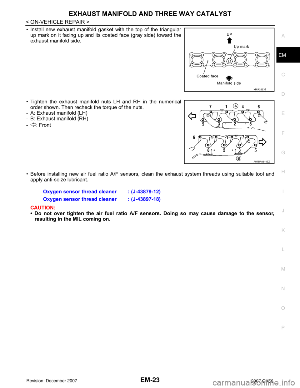
• Install new exhaust manifold gasket with the top of the triangular
up mark on it facing up and its coated face (gray side) toward the
exhaust manifold side.
• Tighten the exhaust manifold nuts LH and RH in the numerical order shown. Then recheck the torque of the nuts.
- A: Exhaust manifold (LH)
- B: Exhaust manifold (RH)
- : Front
• Before installing new air fuel ratio A/F sensors, clean the exhaust system threads using suitable tool and
apply anti-seize lubricant.
CAUTION:
• Do not over tighten the air fuel ratio A/F sen sors. Doing so may cause damage to the sensor,
resulting in the MIL coming on.
KBIA2553E
AWBIA0814ZZ
Oxygen sensor thread cleaner : (J-43879-12)
Oxygen sensor thread cleaner : (J-43897-18)