tow INFINITI QX56 2007 Factory Service Manual
[x] Cancel search | Manufacturer: INFINITI, Model Year: 2007, Model line: QX56, Model: INFINITI QX56 2007Pages: 3061, PDF Size: 64.56 MB
Page 74 of 3061

AT-4
DTC Confirmation Procedure ................................152
Diagnosis Procedure .............................................152
DTC P1845 ATF PRESSURE SWITCH 5 ........154
Description .............................................................154
CONSULT-II Reference Value in Data Monitor
Mode ......................................................................
154
On Board Diagnosis Logic .....................................154
Possible Cause ......................................................154
DTC Confirmation Procedure ................................154
Diagnosis Procedure .............................................154
DTC P1846 ATF PRESSURE SWITCH 6 ........156
Description .............................................................156
CONSULT-II Reference Value in Data Monitor
Mode ......................................................................
156
On Board Diagnosis Logic .....................................156
Possible Cause ......................................................156
DTC Confirmation Procedure ................................156
Diagnosis Procedure .............................................156
MAIN POWER SUPPLY AND GROUND CIR-
CUIT .................................................................
158
Wiring Diagram - AT - MAIN ..................................158
Diagnosis Procedure .............................................159
CLOSED THROTTLE POSITION AND WIDE
OPEN THROTTLE POSITION CIRCUIT .........
161
CONSULT-II Reference Value in Data Monitor
Mode ......................................................................
161
Diagnosis Procedure .............................................161
BRAKE SIGNAL CIRCUIT ..............................162
CONSULT-II Reference Value in Data Monitor
Mode ......................................................................
162
Diagnosis Procedure .............................................162
TOW MODE SWITCH ......................................163
Description .............................................................163
Wiring Diagram - AT - TMSW ................................163
Diagnosis Procedure .............................................164
TROUBLE DIAGNOSIS FOR SYMPTOMS .....165
Wiring Diagram - AT - NONDTC ............................165
A/T Check Indicator Lamp Does Not Come On .....167
Engine Cannot Be Started in "P" or "N" Position ...168
In "P" Position, Vehicle Moves When Pushed .......168
In "N" Position, Vehicle Moves ..............................169
Large Shock ("N" to "D" Position) ..........................170
Vehicle Does Not Creep Backward in "R" Position ..172
Vehicle Does Not Creep Forward in "D" Position ..175
Vehicle Cannot Be Started from D1 .......................177
A/T Does Not Shift: D1→ D2 ..................................179
A/T Does Not Shift: D2→ D3 ..................................181
A/T Does Not Shift: D3→ D4 ..................................183
A/T Does Not Shift: D4→ D5 ..................................185
A/T Does Not Perform Lock-up .............................187
A/T Does Not Hold Lock-up Condition ...................189
Lock-up Is Not Released .......................................190
Engine Speed Does Not Return to Idle .................191
A/T Does Not Shift: 5th gear → 4th gear ..............192
A/T Does Not Shift: 4th gear → 3rd gear ..............194
A/T Does Not Shift: 3rd gear → 2nd gear .............196
A/T Does Not Shift: 2nd gear → 1st gear .............197
Vehicle Does Not Decelerate By Engine Brake ....199
A/T SHIFT LOCK SYSTEM ..............................202
Description ............................................................202
Shift Lock System Electrical Parts Location ..........202
Wiring Diagram - AT - SHIFT ................................203
Shift Lock Control Unit Reference Value ..............204
Component Inspection ..........................................204
SHIFT CONTROL SYSTEM .............................207
Control Device Removal and Installation ..............207
Adjustment of A/T Position ....................................208
Checking of A/T Position .......................................208
ON-VEHICLE SERVICE ...................................209
Oil Pan ..................................................................209
Control Valve with TCM and A/T Fluid Tempera-
ture Sensor 2 ........................................................
210
Rear Oil Seal .........................................................219
AIR BREATHER HOSE ....................................221
Removal and Installation .......................................221
TRANSMISSION ASSEMBLY ..........................223
Removal and Installation (2WD) ...........................223
Removal and Installation (4WD) ...........................225
OVERHAUL ......................................................228
Component ...........................................................228
Oil Channel ...........................................................235
Location of Adjusting Shims, Needle Bearings,
Thrust Washers and Snap Rings ..........................
237
DISASSEMBLY ................................................240
Disassembly ..........................................................240
REPAIR FOR COMPONENT PARTS ..............258
Oil Pump ...............................................................258
Front Sun Gear, 3rd One-Way Clutch ...................260
Front Carrier, Input Clutch, Rear Internal Gear .....262
Mid Sun Gear, Rear Sun Gear, High and Low Re-
verse Clutch Hub ..................................................
267
High and Low Reverse Clutch ..............................272
Direct Clutch .........................................................274
ASSEMBLY ......................................................277
Assembly (1) .........................................................277
Adjustment ............................................................290
Assembly (2) .........................................................292
SERVICE DATA AND SPECIFICATIONS
(SDS) ................................................................
298
General Specification ............................................298
Vehicle Speed When Shifting Gears .....................298
Vehicle Speed When Performing and Releasing
Complete Lock-up .................................................
299
Stall Speed ............................................................299
Page 79 of 3061
PRECAUTIONS
AT-9
< SERVICE INFORMATION >
D
E
F
G
H
I
J
K
L
MA
B
AT
N
O
P
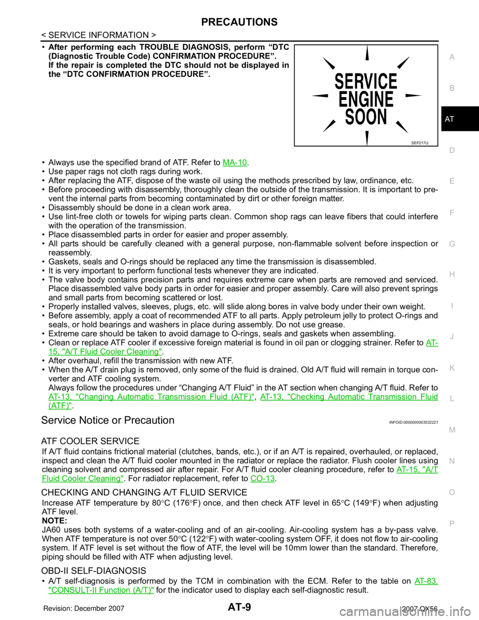
•After performing each TROUBLE DIAGNOSIS, perform “DTC
(Diagnostic Trouble Code) CONFIRMATION PROCEDURE”.
If the repair is completed the DTC should not be displayed in
the “DTC CONFIRMATION PROCEDURE”.
• Always use the specified brand of ATF. Refer to MA-10
.
• Use paper rags not cloth rags during work.
• After replacing the ATF, dispose of the waste oil using the methods prescribed by law, ordinance, etc.
• Before proceeding with disassembly, thoroughly clean the outside of the transmission. It is important to pre-
vent the internal parts from becoming contaminated by dirt or other foreign matter.
• Disassembly should be done in a clean work area.
• Use lint-free cloth or towels for wiping parts clean. Common shop rags can leave fibers that could interfere
with the operation of the transmission.
• Place disassembled parts in order for easier and proper assembly.
• All parts should be carefully cleaned with a general purpose, non-flammable solvent before inspection or
reassembly.
• Gaskets, seals and O-rings should be replaced any time the transmission is disassembled.
• It is very important to perform functional tests whenever they are indicated.
• The valve body contains precision parts and requires extreme care when parts are removed and serviced.
Place disassembled valve body parts in order for easier and proper assembly. Care will also prevent springs
and small parts from becoming scattered or lost.
• Properly installed valves, sleeves, plugs, etc. will slide along bores in valve body under their own weight.
• Before assembly, apply a coat of recommended ATF to all parts. Apply petroleum jelly to protect O-rings and
seals, or hold bearings and washers in place during assembly. Do not use grease.
• Extreme care should be taken to avoid damage to O-rings, seals and gaskets when assembling.
• Clean or replace ATF cooler if excessive foreign material is found in oil pan or clogging strainer. Refer to AT-
15, "A/T Fluid Cooler Cleaning".
• After overhaul, refill the transmission with new ATF.
• When the A/T drain plug is removed, only some of the fluid is drained. Old A/T fluid will remain in torque con-
verter and ATF cooling system.
Always follow the procedures under “Changing A/T Fluid” in the AT section when changing A/T fluid. Refer to
AT-13, "
Changing Automatic Transmission Fluid (ATF)", AT-13, "Checking Automatic Transmission Fluid
(ATF)".
Service Notice or PrecautionINFOID:0000000003532221
ATF COOLER SERVICE
If A/T fluid contains frictional material (clutches, bands, etc.), or if an A/T is repaired, overhauled, or replaced,
inspect and clean the A/T fluid cooler mounted in the radiator or replace the radiator. Flush cooler lines using
cleaning solvent and compressed air after repair. For A/T fluid cooler cleaning procedure, refer to AT-15, "
A/T
Fluid Cooler Cleaning". For radiator replacement, refer to CO-13.
CHECKING AND CHANGING A/T FLUID SERVICE
Increase ATF temperature by 80°C (176°F) once, and then check ATF level in 65°C (149°F) when adjusting
ATF level.
NOTE:
JA60 uses both systems of a water-cooling and of an air-cooling. Air-cooling system has a by-pass valve.
When ATF temperature is not over 50°C (122°F) with water-cooling system OFF, it does not flow to air-cooling
system. If ATF level is set without the flow of ATF, the level will be 10mm lower than the standard. Therefore,
piping should be filled with ATF when adjusting level.
OBD-II SELF-DIAGNOSIS
• A/T self-diagnosis is performed by the TCM in combination with the ECM. Refer to the table on AT-83,
"CONSULT-II Function (A/T)" for the indicator used to display each self-diagnostic result.
SEF217U
Page 86 of 3061
AT-16
< SERVICE INFORMATION >
A/T FLUID
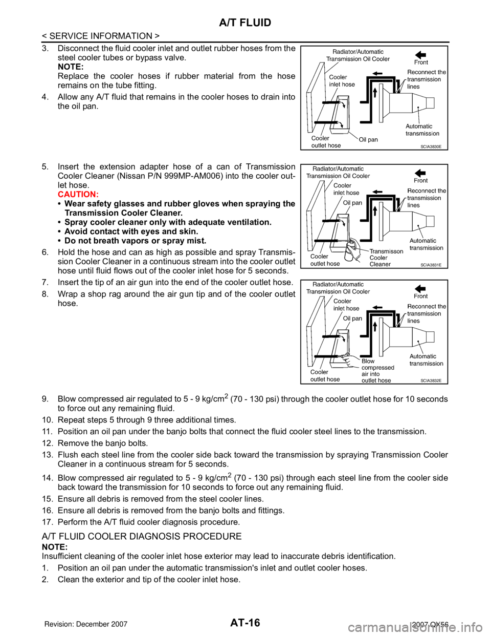
3. Disconnect the fluid cooler inlet and outlet rubber hoses from the
steel cooler tubes or bypass valve.
NOTE:
Replace the cooler hoses if rubber material from the hose
remains on the tube fitting.
4. Allow any A/T fluid that remains in the cooler hoses to drain into
the oil pan.
5. Insert the extension adapter hose of a can of Transmission
Cooler Cleaner (Nissan P/N 999MP-AM006) into the cooler out-
let hose.
CAUTION:
• Wear safety glasses and rubber gloves when spraying the
Transmission Cooler Cleaner.
• Spray cooler cleaner only with adequate ventilation.
• Avoid contact with eyes and skin.
• Do not breath vapors or spray mist.
6. Hold the hose and can as high as possible and spray Transmis-
sion Cooler Cleaner in a continuous stream into the cooler outlet
hose until fluid flows out of the cooler inlet hose for 5 seconds.
7. Insert the tip of an air gun into the end of the cooler outlet hose.
8. Wrap a shop rag around the air gun tip and of the cooler outlet
hose.
9. Blow compressed air regulated to 5 - 9 kg/cm
2 (70 - 130 psi) through the cooler outlet hose for 10 seconds
to force out any remaining fluid.
10. Repeat steps 5 through 9 three additional times.
11. Position an oil pan under the banjo bolts that connect the fluid cooler steel lines to the transmission.
12. Remove the banjo bolts.
13. Flush each steel line from the cooler side back toward the transmission by spraying Transmission Cooler
Cleaner in a continuous stream for 5 seconds.
14. Blow compressed air regulated to 5 - 9 kg/cm
2 (70 - 130 psi) through each steel line from the cooler side
back toward the transmission for 10 seconds to force out any remaining fluid.
15. Ensure all debris is removed from the steel cooler lines.
16. Ensure all debris is removed from the banjo bolts and fittings.
17. Perform the A/T fluid cooler diagnosis procedure.
A/T FLUID COOLER DIAGNOSIS PROCEDURE
NOTE:
Insufficient cleaning of the cooler inlet hose exterior may lead to inaccurate debris identification.
1. Position an oil pan under the automatic transmission's inlet and outlet cooler hoses.
2. Clean the exterior and tip of the cooler inlet hose.
SCIA3830E
SCIA3831E
SCIA3832E
Page 102 of 3061
AT-32
< SERVICE INFORMATION >
A/T CONTROL SYSTEM
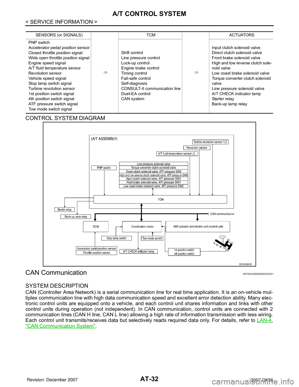
CONTROL SYSTEM DIAGRAM
CAN CommunicationINFOID:0000000003532231
SYSTEM DESCRIPTION
CAN (Controller Area Network) is a serial communication line for real time application. It is an on-vehicle mul-
tiplex communication line with high data communication speed and excellent error detection ability. Many elec-
tronic control units are equipped onto a vehicle, and each control unit shares information and links with other
control units during operation (not independent). In CAN communication, control units are connected with 2
communication lines (CAN H line, CAN L line) allowing a high rate of information transmission with less wiring.
Each control unit transmits/receives data but selectively reads required data only. For details, refer to LAN-4,
"CAN Communication System".
SENSORS (or SIGNALS)
⇒TCM
⇒ACTUATORS
PNP switch
Accelerator pedal position sensor
Closed throttle position signal
Wide open throttle position signal
Engine speed signal
A/T fluid temperature sensor
Revolution sensor
Vehicle speed signal
Stop lamp switch signal
Turbine revolution sensor
1st position switch signal
4th position switch signal
ATF pressure switch signal
Tow mode switch signalShift control
Line pressure control
Lock-up control
Engine brake control
Timing control
Fail-safe control
Self-diagnosis
CONSULT-II communication line
Duet-EA control
CAN systemInput clutch solenoid valve
Direct clutch solenoid valve
Front brake solenoid valve
High and low reverse clutch sole-
noid valve
Low coast brake solenoid valve
Torque converter clutch solenoid
valve
Line pressure solenoid valve
A/T CHECK indicator lamp
Starter relay
Back-up lamp relay
SCIA5624E
Page 113 of 3061
TROUBLE DIAGNOSIS
AT-43
< SERVICE INFORMATION >
D
E
F
G
H
I
J
K
L
MA
B
AT
N
O
P
TROUBLE DIAGNOSIS
DTC Inspection Priority ChartINFOID:0000000003532243
If some DTCs are displayed at the same time, perform inspections one by one based on the following priority
chart.
NOTE:
If DTC U1000 is displayed with other DTCs, first perform the trouble diagnosis for DTC U1000. Refer to
AT- 9 1
.
Fail-SafeINFOID:0000000003532244
The TCM has an electrical fail-safe mode. This mode makes it possible to operate even if there is an error in a
main electronic control input/output signal circuit. In fail-safe mode the transmission is fixed in 2nd, 4th or 5th
(depending on the breakdown position), so the customer should feel “slipping” or “poor acceleration”.
Even when the electronic circuits are normal, under special conditions (for example, when slamming on the
brake with the wheels spinning drastically and stopping the tire rotation), the transmission can go into fail-safe
mode. If this happens, switch “OFF” the ignition switch for 10 seconds, then switch it “ON” again to return to
the normal shift pattern. Therefore, the customer's vehicle has returned to normal, so handle according to the
“diagnostics flow” (Refer to AT-44, "
How To Perform Trouble Diagnosis for Quick and Accurate Repair").
FAIL-SAFE FUNCTION
If any malfunction occurs in a sensor or solenoid, this function controls the A/T to mark driving possible.
Vehicle Speed Sensor
• Signals are input from two systems - from vehicle speed sensor A/T (revolution sensor) installed on the
transmission and from combination meter so normal driving is possible even if there is a malfunction in one
of the systems. And if vehicle speed sensor A/T (revolution sensor) has unusual cases, 5th gear is prohib-
ited.
Accelerator Pedal Position Sensor
• If there is a malfunction in one of the systems, the accelerator opening angle is controlled by ECM according
to a pre-determined accelerator angle to make driving possible. And if there are malfunctions in tow sys-
tems, the engine speed is fixed by ECM to a pre-determined engine speed to make driving possible.
Throttle Position Sensor
• If there is a malfunction in one of the systems, the accelerator opening angle is controlled by ECM according
to a pre-determined accelerator angle to make driving possible. And if there are malfunctions in tow sys-
tems, the accelerator opening angle is controlled by the idle signal sent from the ECM which is based on
input indicating either idle condition or off-idle condition (pre-determined accelerator opening) in order to
make driving possible.
PNP Switch
• In the unlikely event that a malfunction signal enters the TCM, the position indicator is switched “OFF”, the
starter relay is switched “OFF” (starter starting is disabled), the back-up lamp relay switched “OFF” (back-up
lamp is OFF) and the position is fixed to the “D” range to make driving possible.
Starter Relay
• The starter relay is switched “OFF”. (Starter starting is disabled.)
A/T Interlock
• If there is an A/T interlock judgment malfunction, the transmission is fixed in 2nd gear to make driving possi-
ble.
NOTE:
When the vehicle is driven fixed in 2nd gear, a turbine revolution sensor malfunction is displayed,
but this is not a turbine revolution sensor malfunction.
• When the coupling pattern below is detected, the fail-safe action corresponding to the pattern is performed.
A/T INTERLOCK COUPLING PATTERN TABLE
Priority Detected items (DTC)
1 U1000 CAN communication line
2 Except above
Page 129 of 3061

TROUBLE DIAGNOSIS
AT-59
< SERVICE INFORMATION >
D
E
F
G
H
I
J
K
L
MA
B
AT
N
O
P
• Refer to AT-59, "Vehicle Speed When Shifting Gears".
With CONSULT-II
Read the gear position, throttle position and vehicle speed.
Does the A/T shift-up D2
→ D3 at the correct speed?
YES >> GO TO 4.
NO >> Enter a check mark at “Vehicle Does Not Shift: D2 → D3” on the diagnostics worksheet, then con-
tinue the road test.
4.CHECK SHIFT-UP D3 → D4 AND ENGINE BRAKE
When the transmission changes speed D3 → D4, return the accelerator pedal.
Does the A/T shift-up D3
→ D4 and apply the engine brake?
YES >> 1. Stop the vehicle.
2. See AT-59, "
Cruise Test - Part 3".
NO >> Enter a check mark at “Vehicle Does Not Shift: D3 → D4” on the diagnostics worksheet, then con-
tinue the road test.
Cruise Test - Part 3INFOID:0000000003532253
1.CHECK SHIFT-DOWN
During D
5 driving, move gear selector from D → 4 → 3 → 2 → 1.
With CONSULT-II
Read the gear position.
Is downshifting correctly performed?
YES >> GO TO 2.
NO >> Enter a check mark at “Vehicle does not shift” at the corresponding position (5th → 4th, 4th → 3rd,
3rd → 2nd, 2nd → 1st) on the diagnostics worksheet, then continue the road test.
2.CHECK ENGINE BRAKE
Does engine braking effectively reduce speed in 1
1 position?
YES >> 1. Stop the vehicle.
2. Carry out the self-diagnostics. Refer to AT-83, "
CONSULT-II Function (A/T)".
NO >> Enter a check mark at “Vehicle Does Not Decelerate By Engine Brake” on the diagnostics work-
sheet, then continue trouble diagnosis.
Vehicle Speed When Shifting GearsINFOID:0000000003532254
NORMAL MODE
• At half throttle, the accelerator opening is 4/8 of the full opening.
TOW MODE
Final
gear
ratioThrottle positionVehicle speed km/h (MPH)
D
1 →D2D2 →D3D3 →D4D4 →D5D5 →D4D4 →D3D3 →D2D2 →D1
2.937Full throttle 70 - 74
(44 - 46)112 - 120
(70 - 75)176 - 186
(110 - 116)249 - 259
(155 - 161)245 - 255
(152 - 159)166 - 176
(103 - 110)100 - 108
(62 - 67)43 - 47
(27 - 30)
Half throttle 46 - 50
(28 - 31)74 - 82
(46 - 51)103 - 113
(64 - 70)135 - 145
(84 - 90)109 - 119
(68 - 74)69 - 79
(43 - 49)44 - 52
(27 - 32)11 - 1 5
(7 - 10)
3.357Full throttle 61 - 65
(38 - 41)97 - 105
(61 - 66)153 - 163
(95 - 102)236 - 246
(147 - 153)232 - 242
(144 - 151)143 - 153
(89 - 95)87 - 95
(54 - 59)43 - 47
(27 - 29)
Half throttle 41 - 45
(26 - 28)66 - 74
(41 - 46)89 - 99
(56 - 62)11 7 - 1 2 7
(73 - 79)95 - 105
(59 - 65)59 - 69
(37 - 43)38 - 46
(24 - 29)11 - 1 5
(7 - 10)
Final
gear
ratioThrottle positionVehicle speed km/h (MPH)
D
1 →D2D2 →D3D3 →D4D4 →D5D5 →D4D4 →D3D3 →D2D2 →D1
Page 233 of 3061

TOW MODE SWITCH
AT-163
< SERVICE INFORMATION >
D
E
F
G
H
I
J
K
L
MA
B
AT
N
O
P
TOW MODE SWITCH
DescriptionINFOID:0000000003532444
When tow mode switch is “ON”, tow mode switch signals are sent to TCM from combination meter by CAN
communication line.Then it`s a tow mode condition.
Wiring Diagram - AT - TMSWINFOID:0000000003532445
BCWA0498E
Page 234 of 3061

AT-164
< SERVICE INFORMATION >
TOW MODE SWITCH
Diagnosis Procedure
INFOID:0000000003532446
1.CHECK CAN COMMUNICATION LINE
Perform the self-diagnosis. Refer to AT-83, "
CONSULT-II Function (A/T)".
Is any malfunction in the CAN communication indicated in the results?
YES >> Check CAN communication line. Refer to AT- 9 1.
NO >> GO TO 2.
2.CHECK POWER SOURCE
1. Turn ignition switch “ON”. (Do not start engine.)
2. Check the voltage between tow mode switch connector M67 ter-
minal 1 and ground.
OK or NG
OK >>INSPECTION END
NG >> GO TO 3.
3.CHECK TOW MODE SWITCH
1. Turn ignition switch “OFF”.
2. Disconnect tow mode switch connector.
3. Check continuity between tow mode switch terminals 1 and 2.
OK or NG
OK >> GO TO 4.
NG >> Repair or replace tow mode switch.
4.DETECT MALFUNCTIONING ITEM
Check the following items. If any items are damaged, repair or replace damaged parts.
• Harness for short or open between combination meter connector terminal 35 and tow mode switch connec-
tor terminal 1.
• Harness for short or open between tow mode switch connector terminal 2 and ground.
OK or NG
OK >> GO TO 5.
NG >> Repair or replace damaged parts.
5.CHECK COMBINATION METER
Check the combination meter. Refer to DI-15, "
How to Proceed with Trouble Diagnosis".
OK or NG
OK >>INSPECTION END
NO >> Repair or replace damaged parts.
ConditionTo w m o d e
switchData (Approx.)
When ignition switch is turned to “ON”ON 0V
OFF Battery voltage
SCIA5156E
Condition Continuity
Tow mode switch “ON” Yes
Tow mode switch “OFF” No
SCIA5584E
Page 286 of 3061

AT-216
< SERVICE INFORMATION >
ON-VEHICLE SERVICE
7. Install control valve with TCM in transmission case.
CAUTION:
• Make sure that turbine revolution sensor securely installs
turbine revolution sensor hole.
• Hang down revolution sensor harness toward outside so
as not to disturb installation of control valve with TCM.
• Adjust A/T assembly harness connector of control valve
with TCM to terminal hole of transmission case.
• Assemble it so that manual valve cutout is engaged with
manual plate projection.
8. Install bolts (A), (B) and (C) in control valve with TCM.
• : Front
9. Tighten bolt (1), (2) and (3) temporarily to prevent dislocation. Then tighten them in order (1 → 2 → 3),
and then tighten other bolts.
• : Front
10. Tighten control valve with TCM bolts to the specified torque.
Refer to AT-228, "
Component".
SCIA5034E
SCIA5142E
Bolt symbol Length mm (in) Number of bolts
A 42 (1.65) 5
B 55 (2.17) 6
C 40 (1.57) 1
SCIA8074E
SCIA8075E
Page 365 of 3061
ASSEMBLY
AT-295
< SERVICE INFORMATION >
D
E
F
G
H
I
J
K
L
MA
B
AT
N
O
P
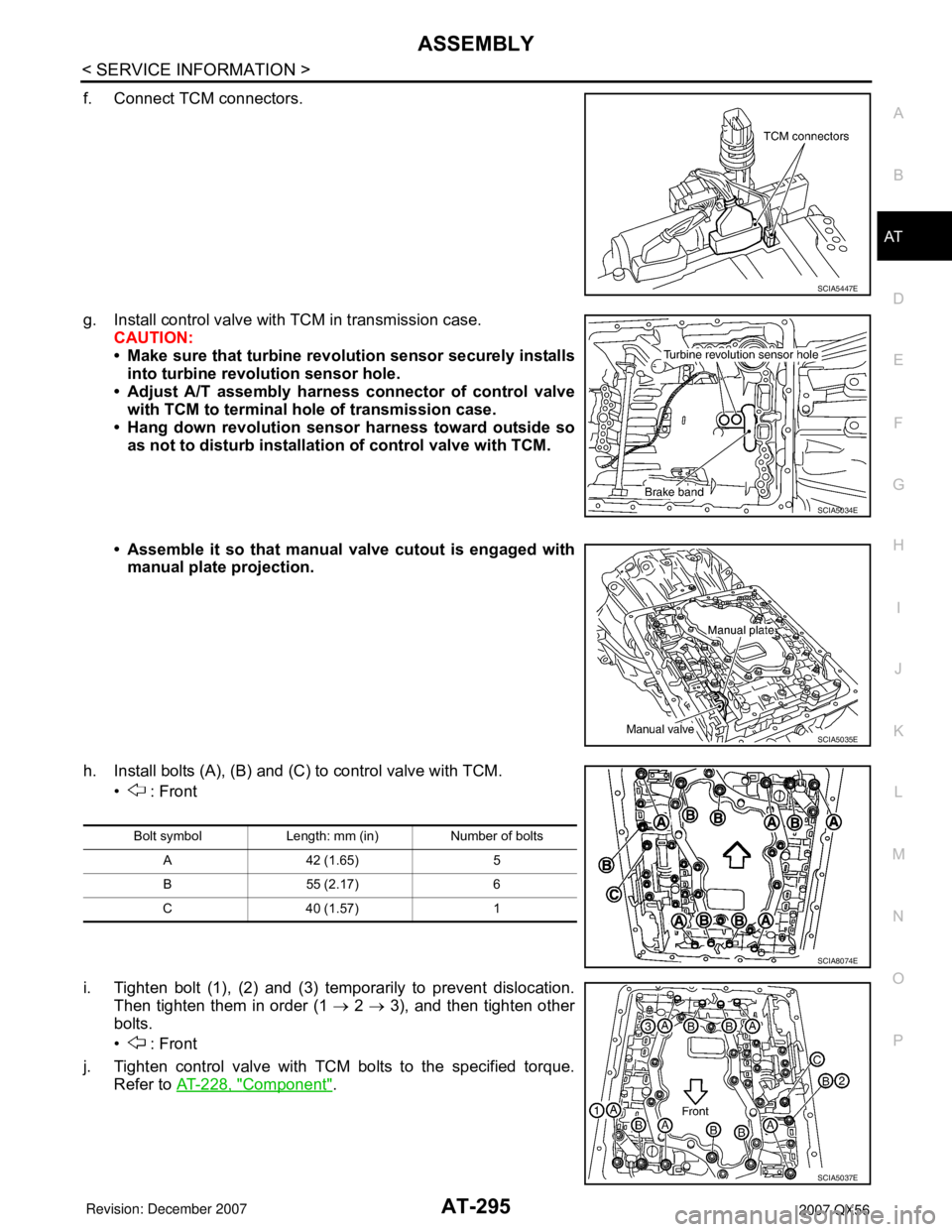
f. Connect TCM connectors.
g. Install control valve with TCM in transmission case.
CAUTION:
• Make sure that turbine revolution sensor securely installs
into turbine revolution sensor hole.
• Adjust A/T assembly harness connector of control valve
with TCM to terminal hole of transmission case.
• Hang down revolution sensor harness toward outside so
as not to disturb installation of control valve with TCM.
• Assemble it so that manual valve cutout is engaged with
manual plate projection.
h. Install bolts (A), (B) and (C) to control valve with TCM.
• : Front
i. Tighten bolt (1), (2) and (3) temporarily to prevent dislocation.
Then tighten them in order (1 → 2 → 3), and then tighten other
bolts.
• : Front
j. Tighten control valve with TCM bolts to the specified torque.
Refer to AT-228, "
Component".
SCIA5447E
SCIA5034E
SCIA5035E
Bolt symbol Length: mm (in) Number of bolts
A 42 (1.65) 5
B 55 (2.17) 6
C 40 (1.57) 1
SCIA8074E
SCIA5037E