tow INFINITI QX56 2007 Factory Workshop Manual
[x] Cancel search | Manufacturer: INFINITI, Model Year: 2007, Model line: QX56, Model: INFINITI QX56 2007Pages: 3061, PDF Size: 64.56 MB
Page 2807 of 3061

SPIRAL CABLE
SRS-37
< SERVICE INFORMATION >
C
D
E
F
G
I
J
K
L
MA
B
SRS
N
O
P
SPIRAL CABLE
Removal and InstallationINFOID:0000000003532874
REMOVAL
CAUTION:
• Before servicing the SRS, turn ignition switch OFF, disconnect both battery cables and wait at least
3 minutes.
• When servicing the SRS, do not work from directly in front of air bag module.
1. Remove the steering wheel. Refer to PS-7
.
2. Remove the column cover upper and lower.
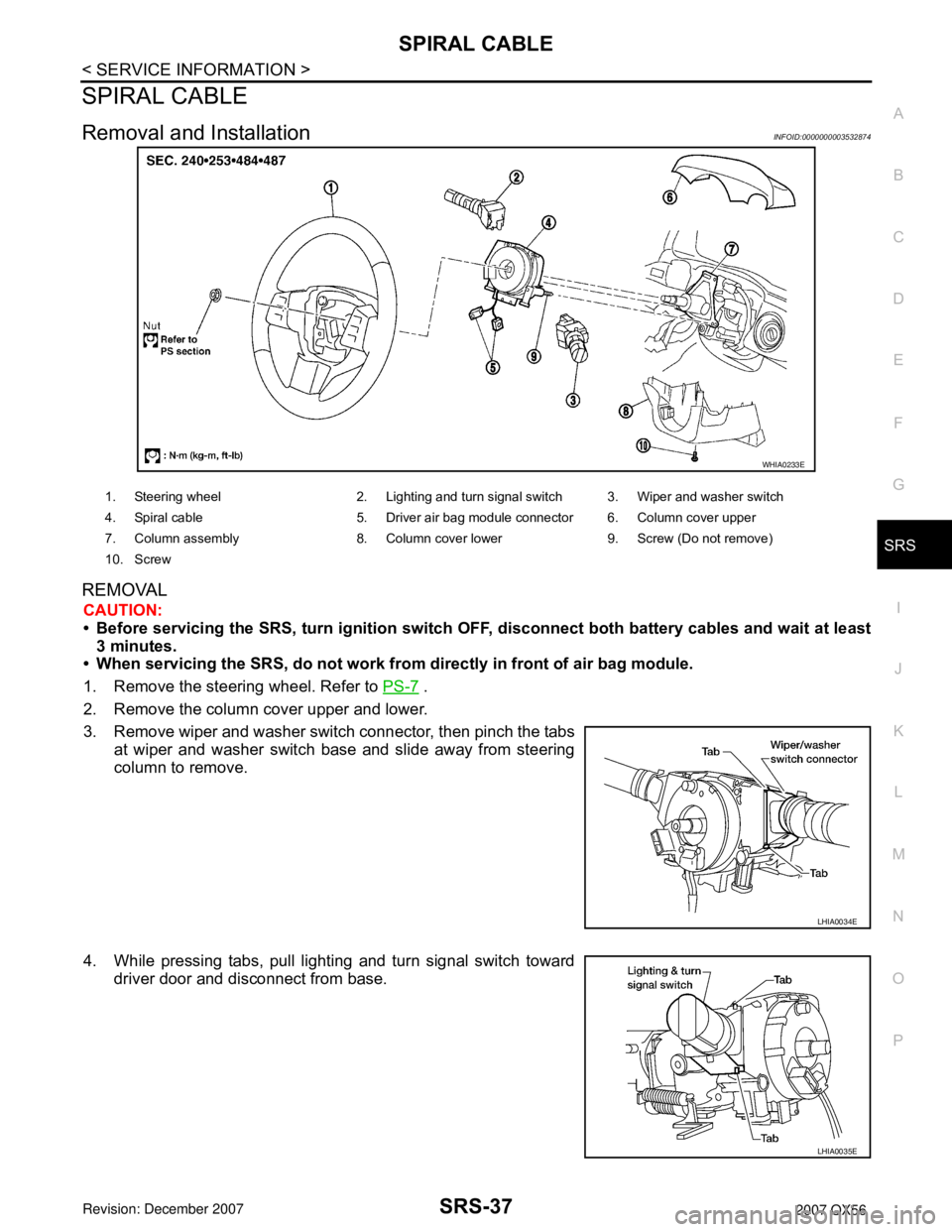
3. Remove wiper and washer switch connector, then pinch the tabs
at wiper and washer switch base and slide away from steering
column to remove.
4. While pressing tabs, pull lighting and turn signal switch toward
driver door and disconnect from base.
WHIA0233E
1. Steering wheel 2. Lighting and turn signal switch 3. Wiper and washer switch
4. Spiral cable 5. Driver air bag module connector 6. Column cover upper
7. Column assembly 8. Column cover lower 9. Screw (Do not remove)
10. Screw
LHIA0034E
LHIA0035E
Page 2817 of 3061

DIAGNOSIS SENSOR UNIT
SRS-47
< SERVICE INFORMATION >
C
D
E
F
G
I
J
K
L
MA
B
SRS
N
O
P
DIAGNOSIS SENSOR UNIT
Removal and InstallationINFOID:0000000003532880
REMOVAL
CAUTION:
• Before servicing the SRS, turn the ignition switch off, disconnect both battery cables and wait at
least 3 minutes.
1. Disconnect the negative and positive battery cables, then wait at least 3 minutes.
2. Disconnect the harness connectors for each air bag module and seat belt pre-tensioner.
3. Remove center console. Refer to IP-10
.
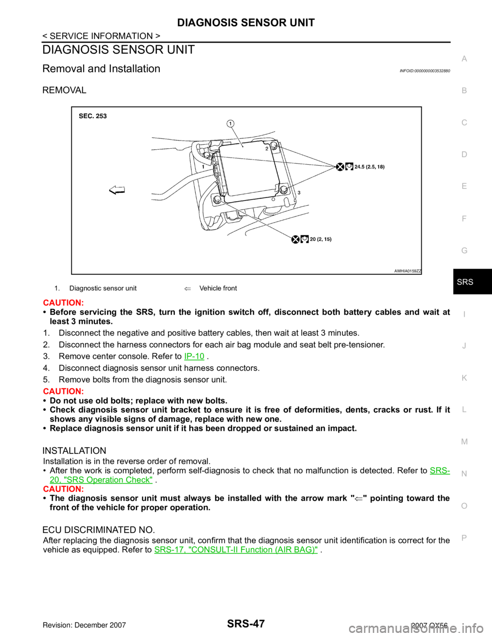
4. Disconnect diagnosis sensor unit harness connectors.
5. Remove bolts from the diagnosis sensor unit.
CAUTION:
• Do not use old bolts; replace with new bolts.
• Check diagnosis sensor unit bracket to ensure it is free of deformities, dents, cracks or rust. If it
shows any visible signs of damage, replace with new one.
• Replace diagnosis sensor unit if it has been dropped or sustained an impact.
INSTALLATION
Installation is in the reverse order of removal.
• After the work is completed, perform self-diagnosis to check that no malfunction is detected. Refer to SRS-
20, "SRS Operation Check" .
CAUTION:
• The diagnosis sensor unit must always be installed with the arrow mark "⇐" pointing toward the
front of the vehicle for proper operation.
ECU DISCRIMINATED NO.
After replacing the diagnosis sensor unit, confirm that the diagnosis sensor unit identification is correct for the
vehicle as equipped. Refer to SRS-17, "
CONSULT-II Function (AIR BAG)" .
1. Diagnostic sensor unit⇐Vehicle front
AWHIA0159ZZ
Page 2827 of 3061

PRECAUTIONS
TF-5
< SERVICE INFORMATION >
C
E
F
G
H
I
J
K
L
MA
B
TF
N
O
P
• Use lint-free cloth or towels for wiping parts clean. Common shop rags can leave fibers that could interfere
with the operation of the transfer.
Page 3055 of 3061

WW-38
< SERVICE INFORMATION >
REAR WIPER AND WASHER SYSTEM
Removal
1. Remove wiper arm. Refer to WW-37, "Rear Wiper Arm".
2. Remove pivot cap.
3. Remove back door lock assembly. Refer to BL-114
.
4. Disconnect rear wiper motor connector.
5. Remove rear wiper motor bolts, and remove rear wiper motor.
Installation
CAUTION:
• Do not drop the wiper motor or cause it to contact other parts.
1. Install rear wiper motor to the vehicle.
2. Connect rear wiper motor connector.
3. Install back door lock assembly. Refer toBL-114
.
4. Install pivot cap.
5. Install wiper arm. Refer toWW-37, "
Rear Wiper Arm".
Rear Washer Nozzle AdjustmentINFOID:0000000003533584
• This vehicle is equipped with a non-adjustable rear washer nozzle.
• If not satisfied with washer fluid spray coverage, confirm that the washer nozzle is installed correctly.
• If the washer nozzle is installed correctly, and the washer fluid spray coverage is not satisfactory, replace the
washer nozzle.
WKIA4567E
1. Wiper arm cover 2. Wiper arm and blade 3. Pivot cap
4. Rear wiper motor 5. Wiper arm stop 6. Rear wiper arm nut
Page 3056 of 3061

REAR WIPER AND WASHER SYSTEM
WW-39
< SERVICE INFORMATION >
C
D
E
F
G
H
I
J
L
MA
B
WW
N
O
P
Rear Washer Tube LayoutINFOID:0000000003533585
NOTE:
Connect the check valve (2) to the washer fluid reservoir tube (1) so
that the directional arrow on the check valve (2) points towards the
washer nozzle tube (3).
Rear Washer NozzleINFOID:0000000003533586
REMOVAL AND INSTALLATION
Removal
1. Remove the rear spoiler. Refer to EI-25.
2. Release retaining clips, and remove washer nozzle.
Installation
Installation is in the reverse order of removal.
Rear Wiper and Washer SwitchINFOID:0000000003533587
REMOVAL AND INSTALLATION
Refer to IP-10, "Removal and Installation".
WKIA4566E
1. Rear washer nozzle 2. Washer fluid reservoir 3. Check valve
WKIA4242E
LKIA0418E