transmission INFINITI QX56 2007 Factory User Guide
[x] Cancel search | Manufacturer: INFINITI, Model Year: 2007, Model line: QX56, Model: INFINITI QX56 2007Pages: 3061, PDF Size: 64.56 MB
Page 86 of 3061
AT-16
< SERVICE INFORMATION >
A/T FLUID
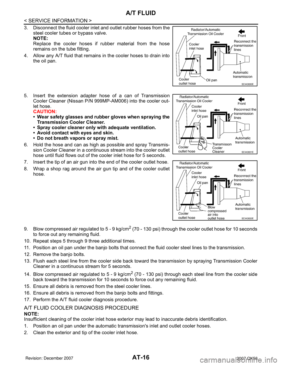
3. Disconnect the fluid cooler inlet and outlet rubber hoses from the
steel cooler tubes or bypass valve.
NOTE:
Replace the cooler hoses if rubber material from the hose
remains on the tube fitting.
4. Allow any A/T fluid that remains in the cooler hoses to drain into
the oil pan.
5. Insert the extension adapter hose of a can of Transmission
Cooler Cleaner (Nissan P/N 999MP-AM006) into the cooler out-
let hose.
CAUTION:
• Wear safety glasses and rubber gloves when spraying the
Transmission Cooler Cleaner.
• Spray cooler cleaner only with adequate ventilation.
• Avoid contact with eyes and skin.
• Do not breath vapors or spray mist.
6. Hold the hose and can as high as possible and spray Transmis-
sion Cooler Cleaner in a continuous stream into the cooler outlet
hose until fluid flows out of the cooler inlet hose for 5 seconds.
7. Insert the tip of an air gun into the end of the cooler outlet hose.
8. Wrap a shop rag around the air gun tip and of the cooler outlet
hose.
9. Blow compressed air regulated to 5 - 9 kg/cm
2 (70 - 130 psi) through the cooler outlet hose for 10 seconds
to force out any remaining fluid.
10. Repeat steps 5 through 9 three additional times.
11. Position an oil pan under the banjo bolts that connect the fluid cooler steel lines to the transmission.
12. Remove the banjo bolts.
13. Flush each steel line from the cooler side back toward the transmission by spraying Transmission Cooler
Cleaner in a continuous stream for 5 seconds.
14. Blow compressed air regulated to 5 - 9 kg/cm
2 (70 - 130 psi) through each steel line from the cooler side
back toward the transmission for 10 seconds to force out any remaining fluid.
15. Ensure all debris is removed from the steel cooler lines.
16. Ensure all debris is removed from the banjo bolts and fittings.
17. Perform the A/T fluid cooler diagnosis procedure.
A/T FLUID COOLER DIAGNOSIS PROCEDURE
NOTE:
Insufficient cleaning of the cooler inlet hose exterior may lead to inaccurate debris identification.
1. Position an oil pan under the automatic transmission's inlet and outlet cooler hoses.
2. Clean the exterior and tip of the cooler inlet hose.
SCIA3830E
SCIA3831E
SCIA3832E
Page 87 of 3061
A/T FLUID
AT-17
< SERVICE INFORMATION >
D
E
F
G
H
I
J
K
L
MA
B
AT
N
O
P
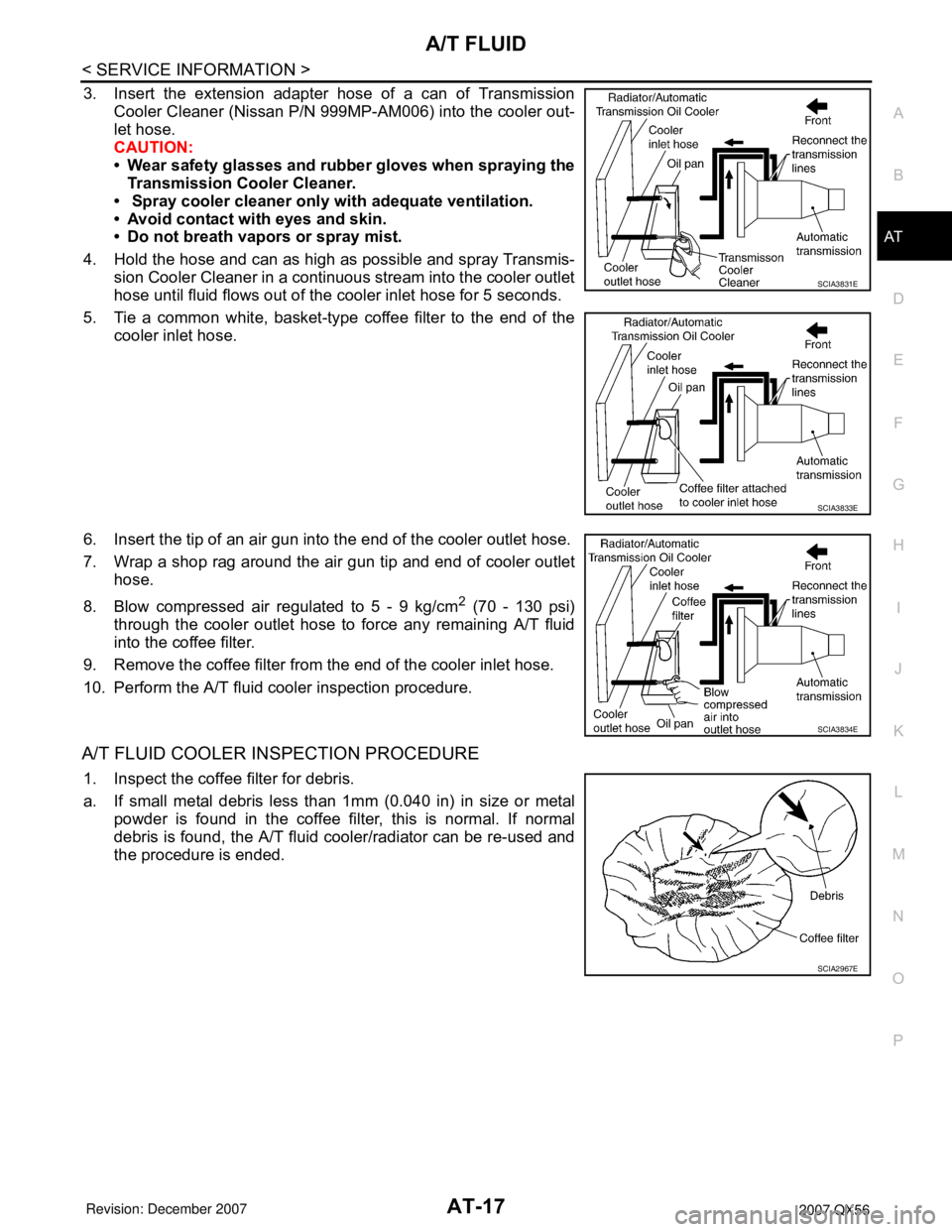
3. Insert the extension adapter hose of a can of Transmission
Cooler Cleaner (Nissan P/N 999MP-AM006) into the cooler out-
let hose.
CAUTION:
• Wear safety glasses and rubber gloves when spraying the
Transmission Cooler Cleaner.
• Spray cooler cleaner only with adequate ventilation.
• Avoid contact with eyes and skin.
• Do not breath vapors or spray mist.
4. Hold the hose and can as high as possible and spray Transmis-
sion Cooler Cleaner in a continuous stream into the cooler outlet
hose until fluid flows out of the cooler inlet hose for 5 seconds.
5. Tie a common white, basket-type coffee filter to the end of the
cooler inlet hose.
6. Insert the tip of an air gun into the end of the cooler outlet hose.
7. Wrap a shop rag around the air gun tip and end of cooler outlet
hose.
8. Blow compressed air regulated to 5 - 9 kg/cm
2 (70 - 130 psi)
through the cooler outlet hose to force any remaining A/T fluid
into the coffee filter.
9. Remove the coffee filter from the end of the cooler inlet hose.
10. Perform the A/T fluid cooler inspection procedure.
A/T FLUID COOLER INSPECTION PROCEDURE
1. Inspect the coffee filter for debris.
a. If small metal debris less than 1mm (0.040 in) in size or metal
powder is found in the coffee filter, this is normal. If normal
debris is found, the A/T fluid cooler/radiator can be re-used and
the procedure is ended.
SCIA3831E
SCIA3833E
SCIA3834E
SCIA2967E
Page 90 of 3061
AT-20
< SERVICE INFORMATION >
A/T CONTROL SYSTEM
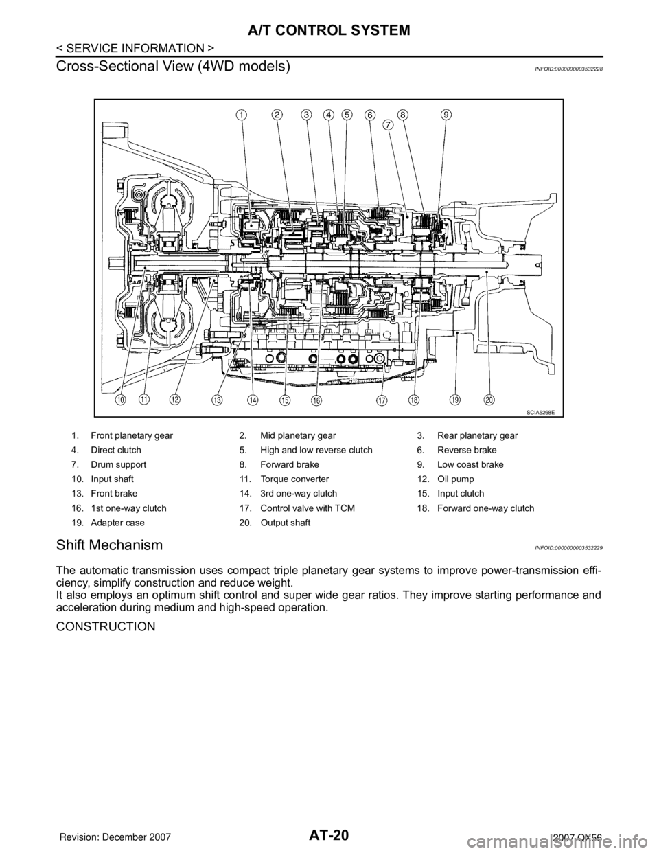
Cross-Sectional View (4WD models)
INFOID:0000000003532228
Shift MechanismINFOID:0000000003532229
The automatic transmission uses compact triple planetary gear systems to improve power-transmission effi-
ciency, simplify construction and reduce weight.
It also employs an optimum shift control and super wide gear ratios. They improve starting performance and
acceleration during medium and high-speed operation.
CONSTRUCTION
1. Front planetary gear 2. Mid planetary gear 3. Rear planetary gear
4. Direct clutch 5. High and low reverse clutch 6. Reverse brake
7. Drum support 8. Forward brake 9. Low coast brake
10. Input shaft 11. Torque converter 12. Oil pump
13. Front brake 14. 3rd one-way clutch 15. Input clutch
16. 1st one-way clutch 17. Control valve with TCM 18. Forward one-way clutch
19. Adapter case 20. Output shaft
SCIA5268E
Page 92 of 3061

AT-22
< SERVICE INFORMATION >
A/T CONTROL SYSTEM
• —Operates
• —Operates during “progressive” acceleration.
• —Operates and effects power transmission while coasting.
• —Line pressure is applied but does not affect power transmission.
• —Operates under conditions shown in HLR/C Operating Condition
• —Operates under conditions shown in LC/B Operating Condition. Delay control is applied during D (4,3,2,1) ⇒N shift.
POWER TRANSMISSION
“N” Position
NNEUTRAL POSI-
TION
D1st
Automatic shift
1⇔2⇔3⇔4⇔5 2nd
3rd
4th
5th
1st
42nd
Automatic shift
3rd1⇔2⇔3⇔4
4th
31st
Automatic shift
1⇔2⇔3⇐4 2nd
3rd
4th
21st
Automatic shift
1⇔2⇐3⇐4 2nd
3rd
4th
11st
Locks (held sta-
tionary in 1st
gear)
1⇐2⇐3⇐4 2nd
3rd
4th Shift position I/C HLR/C D/C R/B FR/B LC/B Fwd/B1st
OWCFwd
OWC3rd
OWCRemarks
SCIA5642E
Page 101 of 3061

A/T CONTROL SYSTEM
AT-31
< SERVICE INFORMATION >
D
E
F
G
H
I
J
K
L
MA
B
AT
N
O
P
TCM FunctionINFOID:0000000003532230
The function of the TCM is to:
• Receive input signals sent from various switches and sensors.
• Determine required line pressure, shifting point, lock-up operation, and engine brake operation.
• Send required output signals to the respective solenoids.
CONTROL SYSTEM OUTLINE
The automatic transmission senses vehicle operating conditions through various sensors or signals. It always
controls the optimum shift position and reduces shifting and lock-up shocks.
1. Front brake 2. Input clutch 3. Direct clutch
4. High and low reverse clutch 5. Reverse brake 6. Forward brake
7. Low coast brake 8. 1st one-way clutch 9. Forward one-way clutch
10. 3rd one-way clutch 11. Front sun gear 12. Input shaft
13. Mid internal gear 14. Front internal gear 15. Rear carrier
16. Rear sun gear 17. Mid sun gear 18. Front carrier
19. Mid carrier 20. Rear internal gear 21. Output shaft
22. Parking gear 23. Parking pawl
SCIA1519E
Page 102 of 3061
AT-32
< SERVICE INFORMATION >
A/T CONTROL SYSTEM
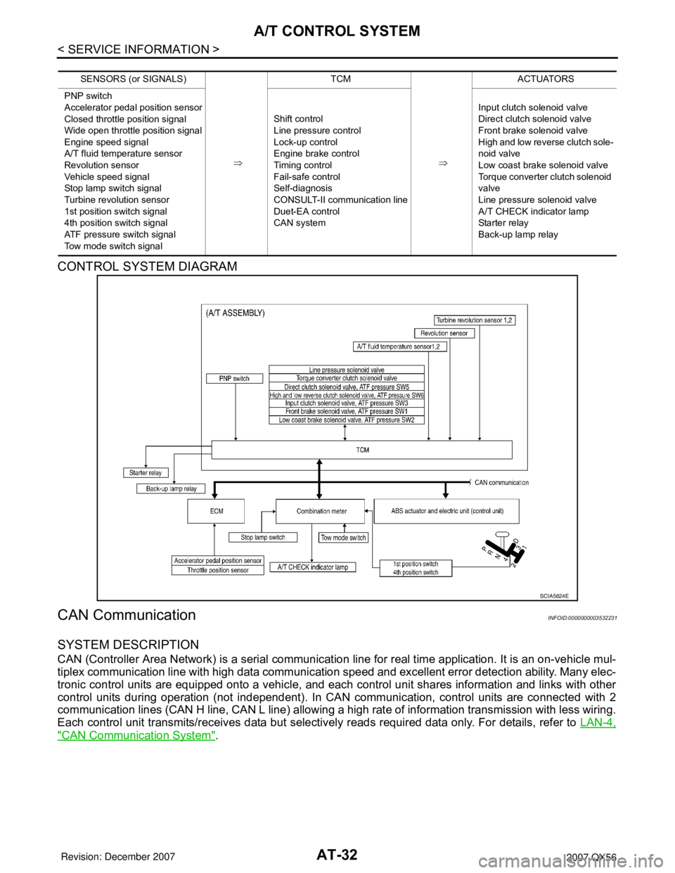
CONTROL SYSTEM DIAGRAM
CAN CommunicationINFOID:0000000003532231
SYSTEM DESCRIPTION
CAN (Controller Area Network) is a serial communication line for real time application. It is an on-vehicle mul-
tiplex communication line with high data communication speed and excellent error detection ability. Many elec-
tronic control units are equipped onto a vehicle, and each control unit shares information and links with other
control units during operation (not independent). In CAN communication, control units are connected with 2
communication lines (CAN H line, CAN L line) allowing a high rate of information transmission with less wiring.
Each control unit transmits/receives data but selectively reads required data only. For details, refer to LAN-4,
"CAN Communication System".
SENSORS (or SIGNALS)
⇒TCM
⇒ACTUATORS
PNP switch
Accelerator pedal position sensor
Closed throttle position signal
Wide open throttle position signal
Engine speed signal
A/T fluid temperature sensor
Revolution sensor
Vehicle speed signal
Stop lamp switch signal
Turbine revolution sensor
1st position switch signal
4th position switch signal
ATF pressure switch signal
Tow mode switch signalShift control
Line pressure control
Lock-up control
Engine brake control
Timing control
Fail-safe control
Self-diagnosis
CONSULT-II communication line
Duet-EA control
CAN systemInput clutch solenoid valve
Direct clutch solenoid valve
Front brake solenoid valve
High and low reverse clutch sole-
noid valve
Low coast brake solenoid valve
Torque converter clutch solenoid
valve
Line pressure solenoid valve
A/T CHECK indicator lamp
Starter relay
Back-up lamp relay
SCIA5624E
Page 106 of 3061
AT-36
< SERVICE INFORMATION >
A/T CONTROL SYSTEM
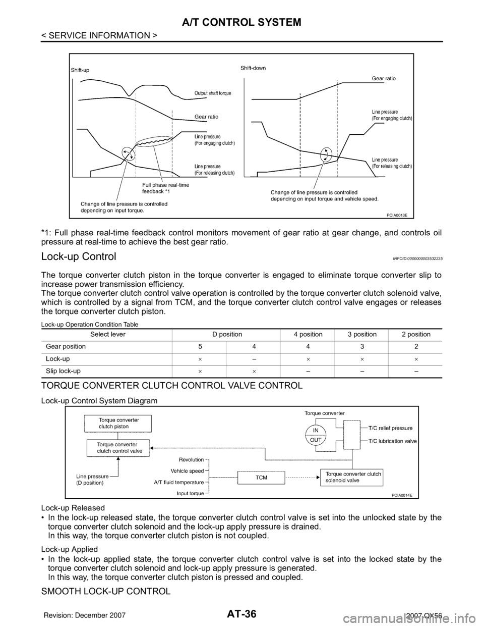
*1: Full phase real-time feedback control monitors movement of gear ratio at gear change, and controls oil
pressure at real-time to achieve the best gear ratio.
Lock-up ControlINFOID:0000000003532235
The torque converter clutch piston in the torque converter is engaged to eliminate torque converter slip to
increase power transmission efficiency.
The torque converter clutch control valve operation is controlled by the torque converter clutch solenoid valve,
which is controlled by a signal from TCM, and the torque converter clutch control valve engages or releases
the torque converter clutch piston.
Lock-up Operation Condition Table
TORQUE CONVERTER CLUTCH CONTROL VALVE CONTROL
Lock-up Control System Diagram
Lock-up Released
• In the lock-up released state, the torque converter clutch control valve is set into the unlocked state by the
torque converter clutch solenoid and the lock-up apply pressure is drained.
In this way, the torque converter clutch piston is not coupled.
Lock-up Applied
• In the lock-up applied state, the torque converter clutch control valve is set into the locked state by the
torque converter clutch solenoid and lock-up apply pressure is generated.
In this way, the torque converter clutch piston is pressed and coupled.
SMOOTH LOCK-UP CONTROL
PCIA0013E
Select lever D position 4 position 3 position 2 position
Gear position 5 4 4 3 2
Lock-up×–×××
Slip lock-up××–––
PCIA0014E
Page 113 of 3061
TROUBLE DIAGNOSIS
AT-43
< SERVICE INFORMATION >
D
E
F
G
H
I
J
K
L
MA
B
AT
N
O
P
TROUBLE DIAGNOSIS
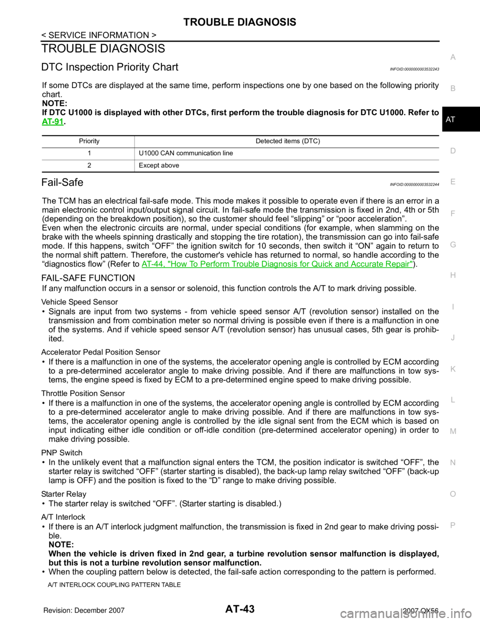
DTC Inspection Priority ChartINFOID:0000000003532243
If some DTCs are displayed at the same time, perform inspections one by one based on the following priority
chart.
NOTE:
If DTC U1000 is displayed with other DTCs, first perform the trouble diagnosis for DTC U1000. Refer to
AT- 9 1
.
Fail-SafeINFOID:0000000003532244
The TCM has an electrical fail-safe mode. This mode makes it possible to operate even if there is an error in a
main electronic control input/output signal circuit. In fail-safe mode the transmission is fixed in 2nd, 4th or 5th
(depending on the breakdown position), so the customer should feel “slipping” or “poor acceleration”.
Even when the electronic circuits are normal, under special conditions (for example, when slamming on the
brake with the wheels spinning drastically and stopping the tire rotation), the transmission can go into fail-safe
mode. If this happens, switch “OFF” the ignition switch for 10 seconds, then switch it “ON” again to return to
the normal shift pattern. Therefore, the customer's vehicle has returned to normal, so handle according to the
“diagnostics flow” (Refer to AT-44, "
How To Perform Trouble Diagnosis for Quick and Accurate Repair").
FAIL-SAFE FUNCTION
If any malfunction occurs in a sensor or solenoid, this function controls the A/T to mark driving possible.
Vehicle Speed Sensor
• Signals are input from two systems - from vehicle speed sensor A/T (revolution sensor) installed on the
transmission and from combination meter so normal driving is possible even if there is a malfunction in one
of the systems. And if vehicle speed sensor A/T (revolution sensor) has unusual cases, 5th gear is prohib-
ited.
Accelerator Pedal Position Sensor
• If there is a malfunction in one of the systems, the accelerator opening angle is controlled by ECM according
to a pre-determined accelerator angle to make driving possible. And if there are malfunctions in tow sys-
tems, the engine speed is fixed by ECM to a pre-determined engine speed to make driving possible.
Throttle Position Sensor
• If there is a malfunction in one of the systems, the accelerator opening angle is controlled by ECM according
to a pre-determined accelerator angle to make driving possible. And if there are malfunctions in tow sys-
tems, the accelerator opening angle is controlled by the idle signal sent from the ECM which is based on
input indicating either idle condition or off-idle condition (pre-determined accelerator opening) in order to
make driving possible.
PNP Switch
• In the unlikely event that a malfunction signal enters the TCM, the position indicator is switched “OFF”, the
starter relay is switched “OFF” (starter starting is disabled), the back-up lamp relay switched “OFF” (back-up
lamp is OFF) and the position is fixed to the “D” range to make driving possible.
Starter Relay
• The starter relay is switched “OFF”. (Starter starting is disabled.)
A/T Interlock
• If there is an A/T interlock judgment malfunction, the transmission is fixed in 2nd gear to make driving possi-
ble.
NOTE:
When the vehicle is driven fixed in 2nd gear, a turbine revolution sensor malfunction is displayed,
but this is not a turbine revolution sensor malfunction.
• When the coupling pattern below is detected, the fail-safe action corresponding to the pattern is performed.
A/T INTERLOCK COUPLING PATTERN TABLE
Priority Detected items (DTC)
1 U1000 CAN communication line
2 Except above
Page 114 of 3061

AT-44
< SERVICE INFORMATION >
TROUBLE DIAGNOSIS
l: NG X: OK
A/T 1st Engine Braking
• When there is an A/T first gear engine brake judgment malfunction, the low coast brake solenoid is switched
“OFF” to avoid the engine brake operation.
Line Pressure Solenoid
• The solenoid is switched “OFF” and the line pressure is set to the maximum hydraulic pressure to make driv-
ing possible.
Torque Converter Clutch Solenoid
• The solenoid is switched “OFF” to release the lock-up.
Low Coast Brake Solenoid
• When a (electrical or functional) malfunction occurs, in order to make driving possible, the engine brake is
not applied in 1st and 2nd gear.
Input Clutch Solenoid
• If a (electrical or functional) malfunction occurs with the solenoid either “ON” or “OFF”, the transmission is
held in 4th gear to make driving possible.
Direct Clutch Solenoid
• If a (electrical or functional) malfunction occurs with the solenoid either “ON” or “OFF”, the transmission is
held in 4th gear to make driving possible.
Front Brake Solenoid
• If a (electrical or functional) malfunction occurs with the solenoid “ON”, in order to make driving possible, the
A/T is held in 5th gear; if the solenoid is OFF, 4th gear.
High and Low Reverse Clutch Solenoid
• If a (electrical or functional) malfunction occurs with the solenoid either “ON” or “OFF”, the transmission is
held in 4th gear to make driving possible.
Turbine Revolution Sensor 1 or 2
• The control is the same as if there were no turbine revolution sensors, 5th gear is prohibited.
How To Perform Trouble Diagnosis for Quick and Accurate RepairINFOID:0000000003532245
INTRODUCTION
The TCM receives a signal from the vehicle speed sensor, accelerator pedal position sensor (throttle position
sensor) or PNP switch and provides shift control or lock-up control via A/T solenoid valves.
The TCM also communicates with the ECM by means of a signal
sent from sensing elements used with the OBD-related parts of the
A/T system for malfunction-diagnostic purposes. The TCM is capa-
ble of diagnosing malfunctioning parts while the ECM can store mal-
functions in its memory.
Input and output signals must always be correct and stable in the
operation of the A/T system. The A/T system must be in good oper-
ating condition and be free of valve seizure, solenoid valve malfunc-
tion, etc.
Gear positionATF pressure switch output
Fail-safe
functionClutch pressure output pattern after fail-safe func-
tion
SW3
(I/C)SW6
(HLR/
C)SW5
(D/C)SW1
(FR/B)SW2
(LC/B)I/C HLR/C D/C FR/B LC/B L/U
A/T interlock
coupling pat-
tern3rd – X X – lHeld in
2nd gearOFF OFF ON OFF OFF OFF
4th – X X –lHeld in
2nd gearOFF OFF ON OFF OFF OFF
5th X X – XlHeld in
2nd gearOFF OFF ON OFF OFF OFF
SAT631IB
Page 121 of 3061
TROUBLE DIAGNOSIS
AT-51
< SERVICE INFORMATION >
D
E
F
G
H
I
J
K
L
MA
B
AT
N
O
P
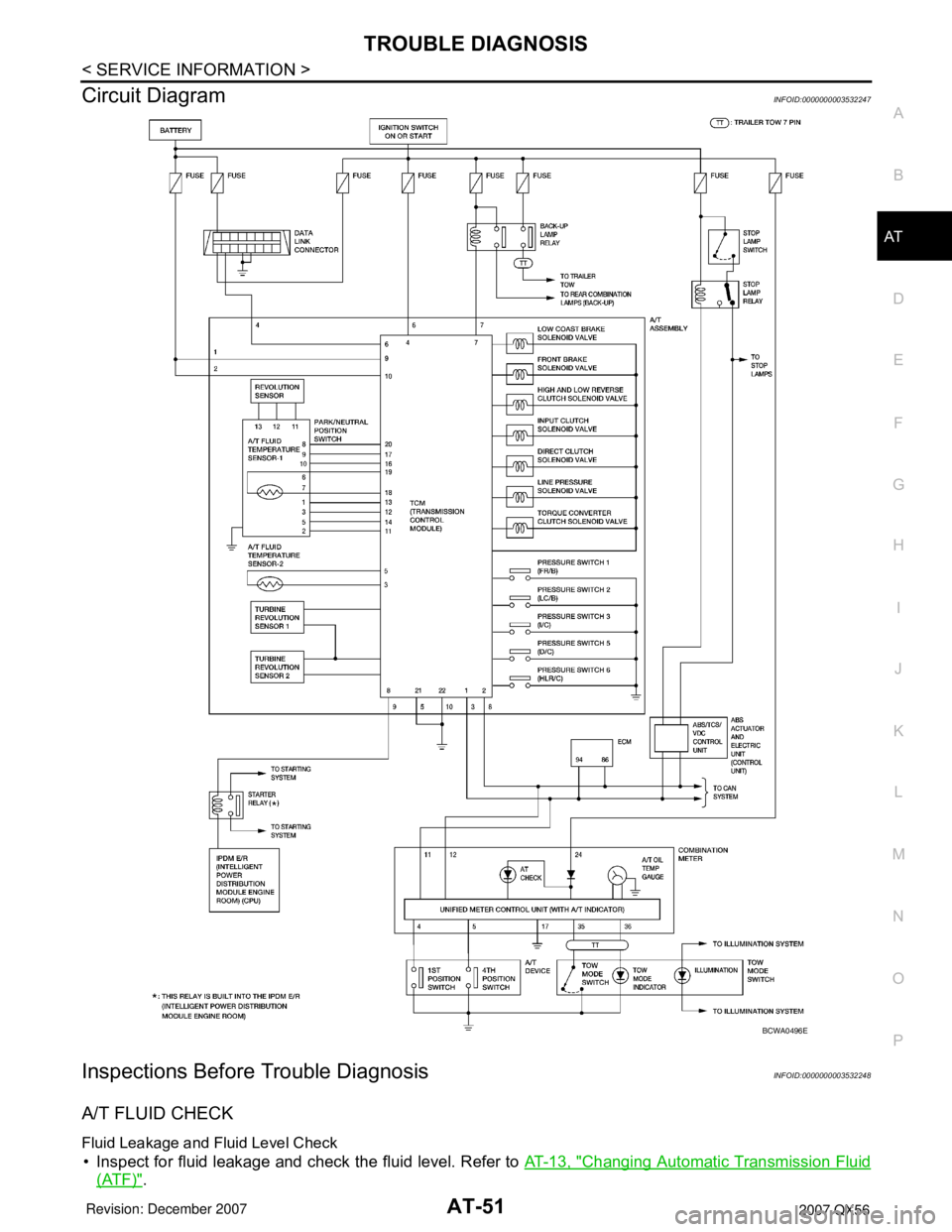
Circuit DiagramINFOID:0000000003532247
Inspections Before Trouble DiagnosisINFOID:0000000003532248
A/T FLUID CHECK
Fluid Leakage and Fluid Level Check
• Inspect for fluid leakage and check the fluid level. Refer to AT-13, "Changing Automatic Transmission Fluid
(ATF)".
BCWA0496E