transmission INFINITI QX56 2007 Factory Owner's Manual
[x] Cancel search | Manufacturer: INFINITI, Model Year: 2007, Model line: QX56, Model: INFINITI QX56 2007Pages: 3061, PDF Size: 64.56 MB
Page 126 of 3061

AT-56
< SERVICE INFORMATION >
TROUBLE DIAGNOSIS
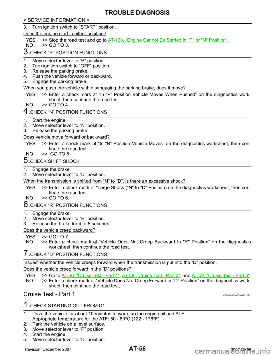
3. Turn ignition switch to “START” position.
Does the engine start in either position?
YES >> Stop the road test and go to AT-168, "Engine Cannot Be Started in "P" or "N" Position".
NO >> GO TO 3.
3.CHECK “P” POSITION FUNCTIONS
1. Move selector lever to “P” position.
2. Turn ignition switch to “OFF” position.
3. Release the parking brake.
4. Push the vehicle forward or backward.
5. Engage the parking brake.
When you push the vehicle with disengaging the parking brake, does it move?
YES >> Enter a check mark at “In “P” Position Vehicle Moves When Pushed” on the diagnostics work-
sheet, then continue the road test.
NO >> GO TO 4.
4.CHECK “N” POSITION FUNCTIONS
1. Start the engine.
2. Move selector lever to “N” position.
3. Release the parking brake.
Does vehicle move forward or backward?
YES >> Enter a check mark at “In “N” Position Vehicle Moves” on the diagnostics worksheet, then con-
tinue the road test.
NO >> GO TO 5.
5.CHECK SHIFT SHOCK
1. Engage the brake.
2. Move selector lever to “D” position.
When the transmission is shifted from
“N” to “D”, is there an excessive shock?
YES >> Enter a check mark at “Large Shock ("N" to "D" Position) on the diagnostics worksheet, then con-
tinue the road test.
NO >> GO TO 6.
6.CHECK “R” POSITION FUNCTIONS
1. Engage the brake.
2. Move selector lever to “R” position.
3. Release the brake for 4 to 5 seconds.
Does the vehicle creep backward?
YES >> GO TO 7.
NO >> Enter a check mark at “Vehicle Does Not Creep Backward In "R" Position” on the diagnostics
worksheet, then continue the road test.
7.CHECK “D” POSITION FUNCTIONS
Inspect whether the vehicle creeps forward when the transmission is put into the “D” position.
Does the vehicle creep forward in the
“D” positions?
YES >> Go to AT-56, "Cruise Test - Part 1", AT-58, "Cruise Test - Part 2", and AT-59, "Cruise Test - Part 3".
NO >> Enter a check mark at “Vehicle Does Not Creep Forward in "D" Position” on the diagnostics work-
sheet, then continue the road test.
Cruise Test - Part 1INFOID:0000000003532251
1.CHECK STARTING OUT FROM D1
1. Drive the vehicle for about 10 minutes to warm up the engine oil and ATF.
Appropriate temperature for the ATF: 50 - 80°C (122 - 176°F)
2. Park the vehicle on a level surface.
3. Move selector lever to “P” position.
4. Start the engine.
5. Move selector lever to “D” position.
Page 128 of 3061

AT-58
< SERVICE INFORMATION >
TROUBLE DIAGNOSIS
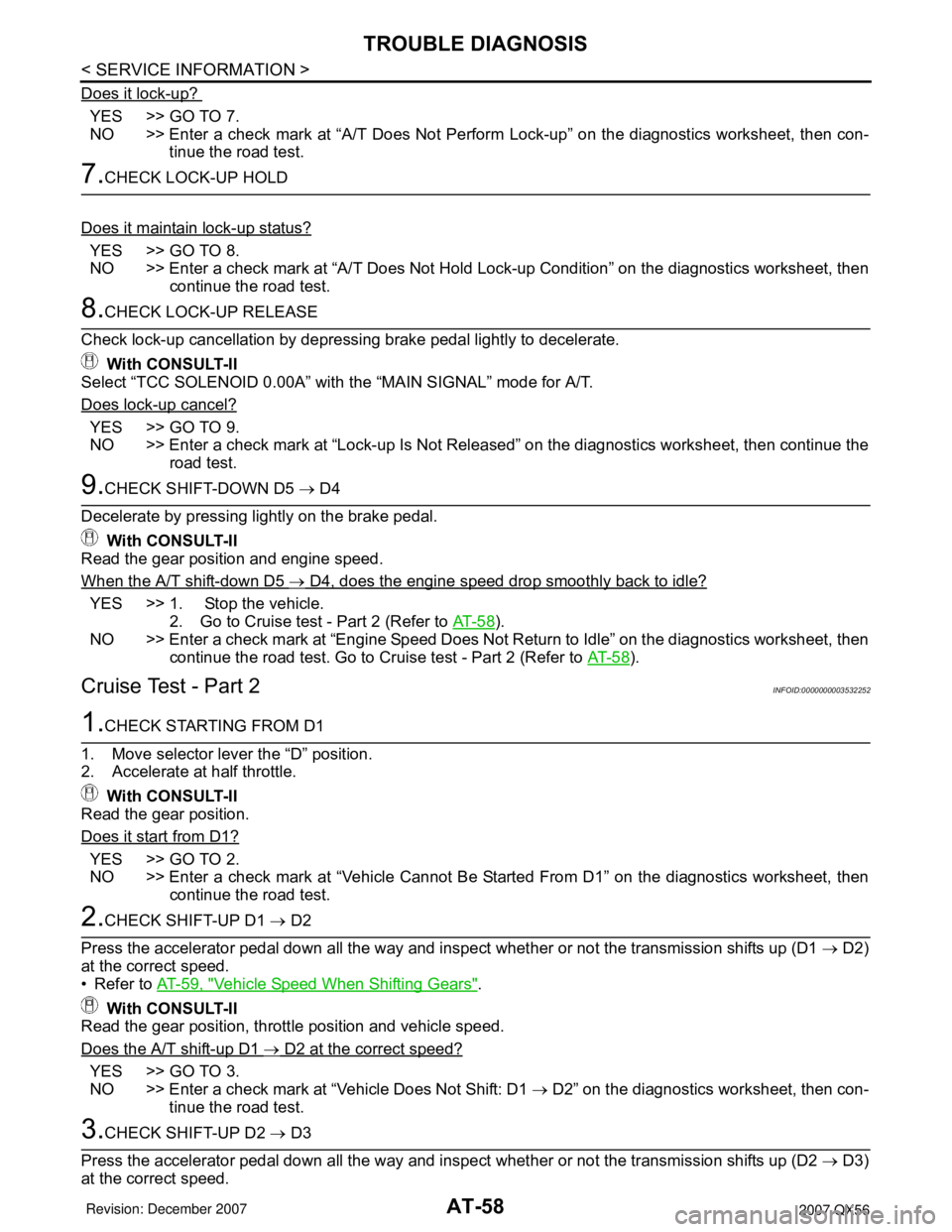
Does it lock-up?
YES >> GO TO 7.
NO >> Enter a check mark at “A/T Does Not Perform Lock-up” on the diagnostics worksheet, then con-
tinue the road test.
7.CHECK LOCK-UP HOLD
Does it maintain lock-up status?
YES >> GO TO 8.
NO >> Enter a check mark at “A/T Does Not Hold Lock-up Condition” on the diagnostics worksheet, then
continue the road test.
8.CHECK LOCK-UP RELEASE
Check lock-up cancellation by depressing brake pedal lightly to decelerate.
With CONSULT-II
Select “TCC SOLENOID 0.00A” with the “MAIN SIGNAL” mode for A/T.
Does lock-up cancel?
YES >> GO TO 9.
NO >> Enter a check mark at “Lock-up Is Not Released” on the diagnostics worksheet, then continue the
road test.
9.CHECK SHIFT-DOWN D5 → D4
Decelerate by pressing lightly on the brake pedal.
With CONSULT-II
Read the gear position and engine speed.
When the A/T shift-down D5
→ D4, does the engine speed drop smoothly back to idle?
YES >> 1. Stop the vehicle.
2. Go to Cruise test - Part 2 (Refer to AT- 5 8
).
NO >> Enter a check mark at “Engine Speed Does Not Return to Idle” on the diagnostics worksheet, then
continue the road test. Go to Cruise test - Part 2 (Refer to AT- 5 8
).
Cruise Test - Part 2INFOID:0000000003532252
1.CHECK STARTING FROM D1
1. Move selector lever the “D” position.
2. Accelerate at half throttle.
With CONSULT-II
Read the gear position.
Does it start from D1?
YES >> GO TO 2.
NO >> Enter a check mark at “Vehicle Cannot Be Started From D1” on the diagnostics worksheet, then
continue the road test.
2.CHECK SHIFT-UP D1 → D2
Press the accelerator pedal down all the way and inspect whether or not the transmission shifts up (D1 → D2)
at the correct speed.
• Refer to AT-59, "
Vehicle Speed When Shifting Gears".
With CONSULT-II
Read the gear position, throttle position and vehicle speed.
Does the A/T shift-up D1
→ D2 at the correct speed?
YES >> GO TO 3.
NO >> Enter a check mark at “Vehicle Does Not Shift: D1 → D2” on the diagnostics worksheet, then con-
tinue the road test.
3.CHECK SHIFT-UP D2 → D3
Press the accelerator pedal down all the way and inspect whether or not the transmission shifts up (D2 → D3)
at the correct speed.
Page 129 of 3061

TROUBLE DIAGNOSIS
AT-59
< SERVICE INFORMATION >
D
E
F
G
H
I
J
K
L
MA
B
AT
N
O
P
• Refer to AT-59, "Vehicle Speed When Shifting Gears".
With CONSULT-II
Read the gear position, throttle position and vehicle speed.
Does the A/T shift-up D2
→ D3 at the correct speed?
YES >> GO TO 4.
NO >> Enter a check mark at “Vehicle Does Not Shift: D2 → D3” on the diagnostics worksheet, then con-
tinue the road test.
4.CHECK SHIFT-UP D3 → D4 AND ENGINE BRAKE
When the transmission changes speed D3 → D4, return the accelerator pedal.
Does the A/T shift-up D3
→ D4 and apply the engine brake?
YES >> 1. Stop the vehicle.
2. See AT-59, "
Cruise Test - Part 3".
NO >> Enter a check mark at “Vehicle Does Not Shift: D3 → D4” on the diagnostics worksheet, then con-
tinue the road test.
Cruise Test - Part 3INFOID:0000000003532253
1.CHECK SHIFT-DOWN
During D
5 driving, move gear selector from D → 4 → 3 → 2 → 1.
With CONSULT-II
Read the gear position.
Is downshifting correctly performed?
YES >> GO TO 2.
NO >> Enter a check mark at “Vehicle does not shift” at the corresponding position (5th → 4th, 4th → 3rd,
3rd → 2nd, 2nd → 1st) on the diagnostics worksheet, then continue the road test.
2.CHECK ENGINE BRAKE
Does engine braking effectively reduce speed in 1
1 position?
YES >> 1. Stop the vehicle.
2. Carry out the self-diagnostics. Refer to AT-83, "
CONSULT-II Function (A/T)".
NO >> Enter a check mark at “Vehicle Does Not Decelerate By Engine Brake” on the diagnostics work-
sheet, then continue trouble diagnosis.
Vehicle Speed When Shifting GearsINFOID:0000000003532254
NORMAL MODE
• At half throttle, the accelerator opening is 4/8 of the full opening.
TOW MODE
Final
gear
ratioThrottle positionVehicle speed km/h (MPH)
D
1 →D2D2 →D3D3 →D4D4 →D5D5 →D4D4 →D3D3 →D2D2 →D1
2.937Full throttle 70 - 74
(44 - 46)112 - 120
(70 - 75)176 - 186
(110 - 116)249 - 259
(155 - 161)245 - 255
(152 - 159)166 - 176
(103 - 110)100 - 108
(62 - 67)43 - 47
(27 - 30)
Half throttle 46 - 50
(28 - 31)74 - 82
(46 - 51)103 - 113
(64 - 70)135 - 145
(84 - 90)109 - 119
(68 - 74)69 - 79
(43 - 49)44 - 52
(27 - 32)11 - 1 5
(7 - 10)
3.357Full throttle 61 - 65
(38 - 41)97 - 105
(61 - 66)153 - 163
(95 - 102)236 - 246
(147 - 153)232 - 242
(144 - 151)143 - 153
(89 - 95)87 - 95
(54 - 59)43 - 47
(27 - 29)
Half throttle 41 - 45
(26 - 28)66 - 74
(41 - 46)89 - 99
(56 - 62)11 7 - 1 2 7
(73 - 79)95 - 105
(59 - 65)59 - 69
(37 - 43)38 - 46
(24 - 29)11 - 1 5
(7 - 10)
Final
gear
ratioThrottle positionVehicle speed km/h (MPH)
D
1 →D2D2 →D3D3 →D4D4 →D5D5 →D4D4 →D3D3 →D2D2 →D1
Page 141 of 3061

TROUBLE DIAGNOSIS
AT-71
< SERVICE INFORMATION >
D
E
F
G
H
I
J
K
L
MA
B
AT
N
O
P
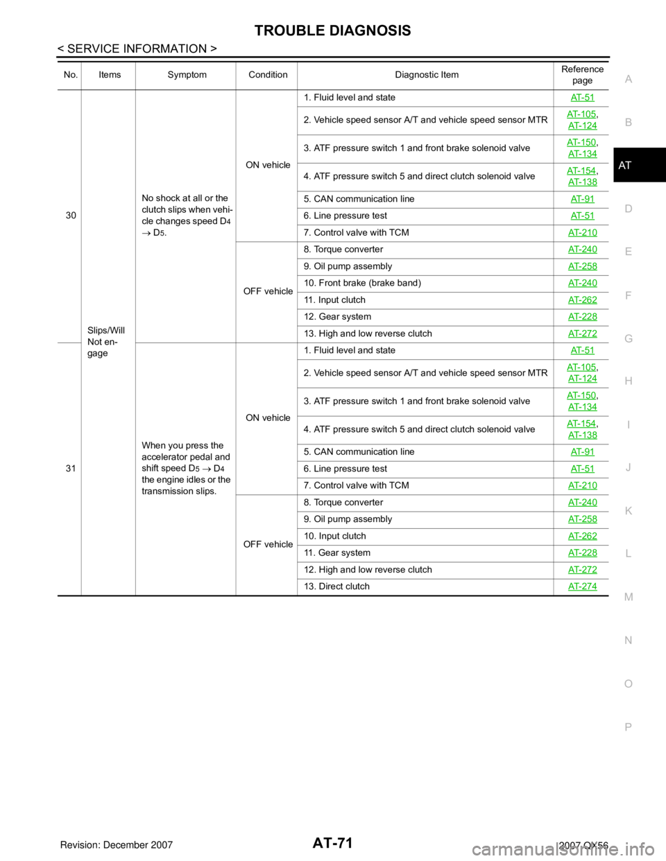
30
Slips/Will
Not en-
gageNo shock at all or the
clutch slips when vehi-
cle changes speed D4
→ D
5.ON vehicle1. Fluid level and stateAT- 5 1
2. Vehicle speed sensor A/T and vehicle speed sensor MTRAT- 1 0 5,
AT-124
3. ATF pressure switch 1 and front brake solenoid valveAT- 1 5 0,
AT-134
4. ATF pressure switch 5 and direct clutch solenoid valveAT- 1 5 4,
AT-138
5. CAN communication lineAT- 9 1
6. Line pressure testAT- 5 1
7. Control valve with TCMAT-210
OFF vehicle8. Torque converterAT-240
9. Oil pump assemblyAT-258
10. Front brake (brake band)AT-240
11. Input clutchAT-262
12. Gear systemAT-228
13. High and low reverse clutchAT-272
31When you press the
accelerator pedal and
shift speed D5 → D4
the engine idles or the
transmission slips.ON vehicle1. Fluid level and stateAT- 5 1
2. Vehicle speed sensor A/T and vehicle speed sensor MTRAT- 1 0 5,
AT-124
3. ATF pressure switch 1 and front brake solenoid valveAT- 1 5 0,
AT-134
4. ATF pressure switch 5 and direct clutch solenoid valveAT- 1 5 4,
AT-138
5. CAN communication lineAT- 9 1
6. Line pressure testAT- 5 1
7. Control valve with TCMAT-210
OFF vehicle8. Torque converterAT-240
9. Oil pump assemblyAT-258
10. Input clutchAT-262
11. Gear systemAT-228
12. High and low reverse clutchAT-272
13. Direct clutchAT-274
No. Items Symptom Condition Diagnostic ItemReference
page
Page 142 of 3061

AT-72
< SERVICE INFORMATION >
TROUBLE DIAGNOSIS
32
Slips/Will
Not en-
gageWhen you press the
accelerator pedal and
shift speed D4 → D3
the engine idles or the
transmission slips.ON vehicle1. Fluid level and stateAT- 5 1
2. Vehicle speed sensor A/T and vehicle speed sensor MTRAT- 1 0 5,
AT- 1 2 4
3. ATF pressure switch 3 and input clutch solenoid valveAT- 1 5 2,
AT- 1 3 0
4. ATF pressure switch 1 and front brake solenoid valveAT- 1 5 0,
AT- 1 3 4
5. CAN communication lineAT- 9 1
6. Line pressure testAT- 5 1
7. Control valve with TCMAT- 2 1 0
OFF vehicle8. Torque converter AT- 2 4 0
9. Oil pump assemblyAT- 2 5 8
10. 3rd one-way clutchAT- 2 6 0
11. Gear systemAT- 2 2 8
12. High and low reverse clutchAT- 2 7 2
13. Forward one- way clutch (Parts behind drum support is
impossible to perform inspection by disassembly. Refer to AT-
19, AT- 2 0.)AT- 2 4 0
14. Forward brake (Parts behind drum support is impossible
to perform inspection by disassembly. Refer to AT- 1 9
, AT- 2 0.)AT- 2 4 0
33When you press the
accelerator pedal and
shift speed D3 → D2
the engine idles or the
transmission slips.ON vehicle1. Fluid level and stateAT- 5 1
2. Vehicle speed sensor A/T and vehicle speed sensor MTRAT- 1 0 5,
AT- 1 2 4
3. ATF pressure switch 6, high and low reverse clutch sole-
noid valveAT- 1 5 6,
AT- 1 4 2
4. ATF pressure switch 5 and direct clutch solenoid valveAT- 1 5 4,
AT- 1 3 8
5. CAN communication lineAT- 9 1
6. Line pressure testAT- 5 1
7. Control valve with TCMAT- 2 1 0
OFF vehicle8. Torque converterAT- 2 4 0
9. Oil pump assemblyAT- 2 5 8
10. 3rd one-way clutchAT- 2 6 0
11. Gear systemAT- 2 2 8
12. Direct clutchAT- 2 7 4
13. Forward brake (Parts behind drum support is impossible
to perform inspection by disassembly. Refer to AT- 1 9
, AT- 2 0.)AT- 2 4 0
No. Items Symptom Condition Diagnostic ItemReference
page
Page 143 of 3061

TROUBLE DIAGNOSIS
AT-73
< SERVICE INFORMATION >
D
E
F
G
H
I
J
K
L
MA
B
AT
N
O
P
34
Slips/Will
Not En-
gageWhen you press the
accelerator pedal and
shift speed D2 → D1
the engine idles or the
transmission slips.ON vehicle1. Fluid level and stateAT- 5 1
2. Vehicle speed sensor A/T and vehicle speed sensor MTRAT- 1 0 5,
AT-124
3. ATF pressure switch 5 and direct clutch solenoid valveAT- 1 5 4,
AT-138
4. CAN communication lineAT- 9 1
5. Line pressure testAT- 5 1
6. Control valve with TCMAT-210
OFF vehicle7. Torque converterAT-240
8. Oil pump assemblyAT-258
9. 3rd one-way clutchAT-260
10. 1st one-way clutchAT-267
11. Gear systemAT-228
12. Reverse brakeAT-240
13. Forward one- way clutch (Parts behind drum support is
impossible to perform inspection by disassembly. Refer to AT-
19, AT- 2 0.)AT-240
14. Forward brake (Parts behind drum support is impossible
to perform inspection by disassembly. Refer to AT- 1 9
, AT- 2 0.)AT-240
35With selector lever in
“D” position, accelera-
tion is extremely poor.ON vehicle1. Fluid level and stateAT- 5 1
2. Line pressure testAT- 5 1
3. Accelerator pedal position sensorAT- 11 7
4. CAN communication lineAT- 9 1
5. PNP switchAT- 9 9
6. Control cable adjustmentAT-208
7. Control valve with TCMAT-210
OFF vehicle8. Torque converterAT-240
9. Oil pump assemblyAT-258
10. 1st one-way clutchAT-267
11. Gear systemAT-228
12. Reverse brakeAT-240
13. Forward one- way clutch (Parts behind drum support is
impossible to perform inspection by disassembly. Refer to AT-
19, AT- 2 0.)AT-240
14. Forward brake (Parts behind drum support is impossible
to perform inspection by disassembly. Refer to AT- 1 9
, AT- 2 0.)AT-240
No. Items Symptom Condition Diagnostic ItemReference
page
Page 150 of 3061

AT-80
< SERVICE INFORMATION >
TROUBLE DIAGNOSIS
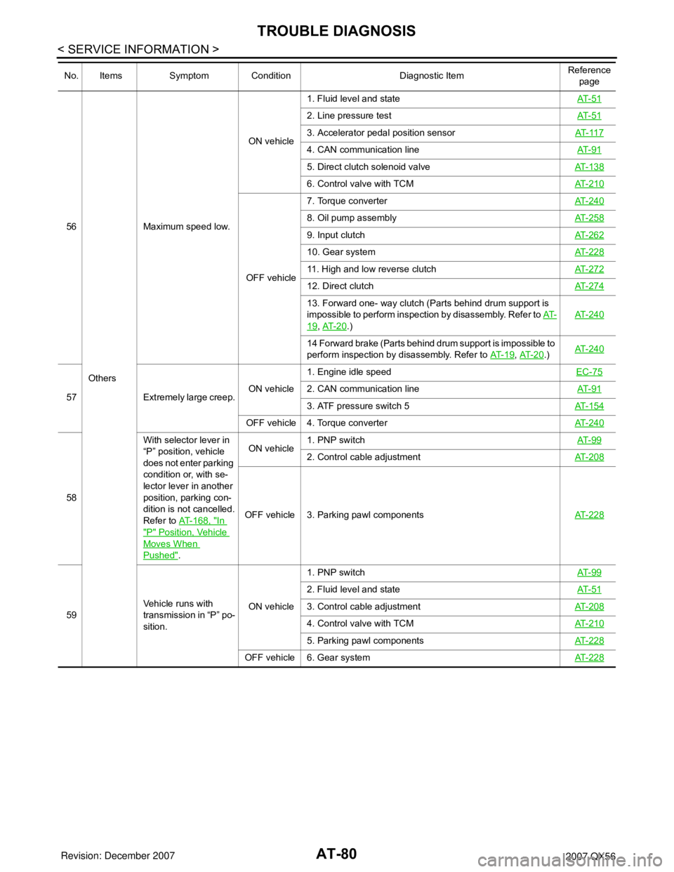
56
OthersMaximum speed low.ON vehicle1. Fluid level and stateAT- 5 1
2. Line pressure testAT- 5 1
3. Accelerator pedal position sensorAT- 11 7
4. CAN communication lineAT- 9 1
5. Direct clutch solenoid valveAT- 1 3 8
6. Control valve with TCMAT- 2 1 0
OFF vehicle7. Torque converterAT- 2 4 0
8. Oil pump assemblyAT- 2 5 8
9. Input clutchAT- 2 6 2
10. Gear systemAT- 2 2 8
11. High and low reverse clutchAT- 2 7 2
12. Direct clutchAT- 2 7 4
13. Forward one- way clutch (Parts behind drum support is
impossible to perform inspection by disassembly. Refer to AT-
19, AT- 2 0.)AT- 2 4 0
14 Forward brake (Parts behind drum support is impossible to
perform inspection by disassembly. Refer to AT- 1 9
, AT- 2 0.)AT- 2 4 0
57 Extremely large creep.ON vehicle1. Engine idle speed EC-75
2. CAN communication lineAT- 9 1
3. ATF pressure switch 5AT- 1 5 4
OFF vehicle 4. Torque converterAT- 2 4 0
58With selector lever in
“P” position, vehicle
does not enter parking
condition or, with se-
lector lever in another
position, parking con-
dition is not cancelled.
Refer to AT-168, "
In
"P" Position, Vehicle
Moves When
Pushed".ON vehicle1. PNP switchAT- 9 9
2. Control cable adjustmentAT- 2 0 8
OFF vehicle 3. Parking pawl componentsAT- 2 2 8
59Vehicle runs with
transmission in “P” po-
sition.ON vehicle1. PNP switchAT- 9 9
2. Fluid level and stateAT- 5 1
3. Control cable adjustmentAT- 2 0 8
4. Control valve with TCMAT- 2 1 0
5. Parking pawl componentsAT- 2 2 8
OFF vehicle 6. Gear systemAT- 2 2 8
No. Items Symptom Condition Diagnostic ItemReference
page
Page 151 of 3061

TROUBLE DIAGNOSIS
AT-81
< SERVICE INFORMATION >
D
E
F
G
H
I
J
K
L
MA
B
AT
N
O
P
60
OthersVehicle runs with
transmission in “N” po-
sition.
Refer to AT- 1 6 9 , "In
"N" Position, Vehicle
Moves".ON vehicle1. PNP switchAT- 9 9
2. Fluid level and stateAT- 5 1
3. Control cable adjustmentAT-208
4. Control valve with TCMAT-210
OFF vehicle5. Input clutchAT-262
6. Gear systemAT-228
7. Direct clutchAT-274
8. Reverse brakeAT-240
9. Forward one- way clutch (Parts behind drum support is im-
possible to perform inspection by disassembly. Refer to AT-
19, AT- 2 0.)AT-240
10. Forward brake (Parts behind drum support is impossible
to perform inspection by disassembly. Refer to AT- 1 9
, AT- 2 0.)AT-240
61Engine does not start
in “N” or “P” position.
Refer to AT- 1 6 8 , "En-
gine Cannot Be Start-
ed in "P" or "N"
Position".ON vehicle1. Ignition switch and starterPG-3
, SC-
9
2. Control cable adjustmentAT-208
3. PNP switchAT- 9 9
62Engine starts in posi-
tions other than “N” or
“P”.ON vehicle1. Ignition switch and starterPG-3
, SC-
9
2. Control cable adjustmentAT-208
3. PNP switchAT- 9 9
63 Engine stall.ON vehicle1. Fluid level and stateAT- 5 1
2. Engine speed signalAT-109
3. Turbine revolution sensorAT-103
4. Torque converter clutch solenoid valveAT- 111
5. CAN communication lineAT- 9 1
6. Control valve with TCMAT-210
OFF vehicle 7. Torque converterAT-240
64Engine stalls when se-
lect lever shifted “N” →
“D”, “R”.ON vehicle1. Fluid level and stateAT- 5 1
2. Engine speed signalAT-109
3. Turbine revolution sensorAT-103
4. Torque converter clutch solenoid valveAT- 111
5. CAN communication lineAT- 9 1
6. Control valve with TCMAT-210
OFF vehicle 7. Torque converterAT-240
No. Items Symptom Condition Diagnostic ItemReference
page
Page 161 of 3061

DTC U1000 CAN COMMUNICATION LINE
AT-91
< SERVICE INFORMATION >
D
E
F
G
H
I
J
K
L
MA
B
AT
N
O
P
DTC U1000 CAN COMMUNICATION LINE
DescriptionINFOID:0000000003532260
CAN (Controller Area Network) is a serial communication line for real time application. It is an on-vehicle mul-
tiplex communication line with high data communication speed and excellent malfunction detection ability.
Many electronic control units are equipped onto a vehicle, and each control unit shares information and links
with other control units during operation (not independent). In CAN communication, control units are con-
nected with 2 communication lines (CAN H line, CAN L line) allowing a high rate of information transmission
with less wiring. Each control unit transmits/receives data but selectively reads required data only.
On Board Diagnosis LogicINFOID:0000000003532261
• This is an OBD-II self-diagnostic item.
• Diagnostic trouble code “U1000 CAN COMM CIRCUIT” with CONSULT-II is detected when TCM cannot
communicate to other control units.
Possible CauseINFOID:0000000003532262
Harness or connectors
(CAN communication line is open or shorted.)
DTC Confirmation ProcedureINFOID:0000000003532263
NOTE:
If “DTC Confirmation Procedure” has been previously performed, always turn ignition switch “OFF”
and wait at least 10 seconds before performing the next test.
After the repair, perform the following procedure to confirm the malfunction is eliminated.
WITH CONSULT-II
1. Turn ignition switch “ON”. (Do not start engine.)
2. Select “DATA MONITOR” mode for “ENGINE” with CONSULT-II.
3. Start engine and wait for at least 6 seconds.
4. If DTC is detected, go to AT-93, "
Diagnosis Procedure".
WITH GST
Follow the procedure “WITH CONSULT-II”.
BCIA0031E
Page 169 of 3061

DTC P0705 PARK/NEUTRAL POSITION SWITCH
AT-99
< SERVICE INFORMATION >
D
E
F
G
H
I
J
K
L
MA
B
AT
N
O
P
DTC P0705 PARK/NEUTRAL POSITION SWITCH
DescriptionINFOID:0000000003532278
• The park/neutral position (PNP) switch includes a transmission position switch.
• The transmission range switch detects the selector lever position and sends a signal to the TCM.
CONSULT-II Reference Value in Data Monitor ModeINFOID:0000000003532279
On Board Diagnosis LogicINFOID:0000000003532280
• This is an OBD-II self-diagnostic item.
• Diagnostic trouble code “P0705 PNP SW/CIRC” with CONSULT-II is detected under the following condi-
tions.
- When TCM does not receive the correct voltage signal from the PNP switch 1, 2, 3, 4 based on the gear
position.
- When no other position but “P” position is detected from “N” positions.
Possible CauseINFOID:0000000003532281
• Harness or connectors
[The park/neutral position (PNP) switch 1, 2, 3, 4 and TCM circuit is open or shorted.]
• Park/neutral position (PNP) switch 1, 2, 3, 4
DTC Confirmation ProcedureINFOID:0000000003532282
CAUTION:
Always drive vehicle at a safe speed.
NOTE:
If “DTC Confirmation Procedure” has been previously performed, always turn ignition switch “OFF”
and wait at least 10 seconds before performing the next test.
After the repair, perform the following procedure to confirm the malfunction is eliminated.
WITH CONSULT-II
1. Turn ignition switch “ON”. (Do not start engine.)
2. Select “DATA MONITOR” mode for “ENGINE” with CONSULT-II.
3. Start engine.
4. Drive vehicle and maintain the following conditions for at least 2
consecutive seconds.
THRTL POS SEN: More than 1.2V
5. If DTC is detected, go to AT-100, "
Diagnosis Procedure".
WITH GST
Follow the procedure “With CONSULT-II”.
Item name Condition Display value
SLCTLVR POSI Selector lever in “N”,“P” positions. N/P
Selector lever in “R” position. R
Selector lever in “D” position. D
Selector lever in “4” position. 4
Selector lever in “3” position. 3
Selector lever in “2” position. 2
Selector lever in “1” position. 1
BCIA0031E