transmission fluid INFINITI QX56 2007 Factory User Guide
[x] Cancel search | Manufacturer: INFINITI, Model Year: 2007, Model line: QX56, Model: INFINITI QX56 2007Pages: 3061, PDF Size: 64.56 MB
Page 121 of 3061
TROUBLE DIAGNOSIS
AT-51
< SERVICE INFORMATION >
D
E
F
G
H
I
J
K
L
MA
B
AT
N
O
P
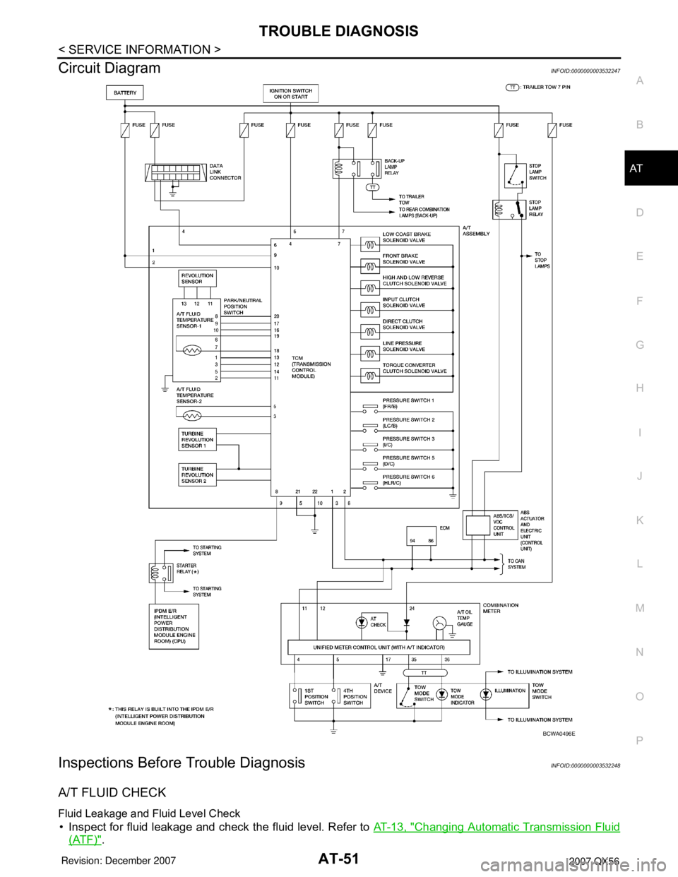
Circuit DiagramINFOID:0000000003532247
Inspections Before Trouble DiagnosisINFOID:0000000003532248
A/T FLUID CHECK
Fluid Leakage and Fluid Level Check
• Inspect for fluid leakage and check the fluid level. Refer to AT-13, "Changing Automatic Transmission Fluid
(ATF)".
BCWA0496E
Page 141 of 3061
TROUBLE DIAGNOSIS
AT-71
< SERVICE INFORMATION >
D
E
F
G
H
I
J
K
L
MA
B
AT
N
O
P
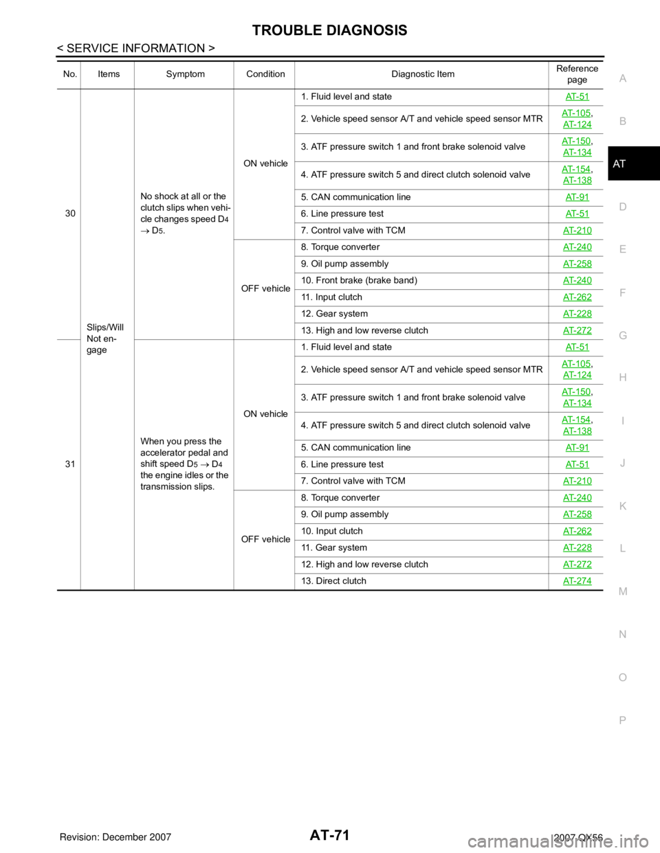
30
Slips/Will
Not en-
gageNo shock at all or the
clutch slips when vehi-
cle changes speed D4
→ D
5.ON vehicle1. Fluid level and stateAT- 5 1
2. Vehicle speed sensor A/T and vehicle speed sensor MTRAT- 1 0 5,
AT-124
3. ATF pressure switch 1 and front brake solenoid valveAT- 1 5 0,
AT-134
4. ATF pressure switch 5 and direct clutch solenoid valveAT- 1 5 4,
AT-138
5. CAN communication lineAT- 9 1
6. Line pressure testAT- 5 1
7. Control valve with TCMAT-210
OFF vehicle8. Torque converterAT-240
9. Oil pump assemblyAT-258
10. Front brake (brake band)AT-240
11. Input clutchAT-262
12. Gear systemAT-228
13. High and low reverse clutchAT-272
31When you press the
accelerator pedal and
shift speed D5 → D4
the engine idles or the
transmission slips.ON vehicle1. Fluid level and stateAT- 5 1
2. Vehicle speed sensor A/T and vehicle speed sensor MTRAT- 1 0 5,
AT-124
3. ATF pressure switch 1 and front brake solenoid valveAT- 1 5 0,
AT-134
4. ATF pressure switch 5 and direct clutch solenoid valveAT- 1 5 4,
AT-138
5. CAN communication lineAT- 9 1
6. Line pressure testAT- 5 1
7. Control valve with TCMAT-210
OFF vehicle8. Torque converterAT-240
9. Oil pump assemblyAT-258
10. Input clutchAT-262
11. Gear systemAT-228
12. High and low reverse clutchAT-272
13. Direct clutchAT-274
No. Items Symptom Condition Diagnostic ItemReference
page
Page 142 of 3061

AT-72
< SERVICE INFORMATION >
TROUBLE DIAGNOSIS
32
Slips/Will
Not en-
gageWhen you press the
accelerator pedal and
shift speed D4 → D3
the engine idles or the
transmission slips.ON vehicle1. Fluid level and stateAT- 5 1
2. Vehicle speed sensor A/T and vehicle speed sensor MTRAT- 1 0 5,
AT- 1 2 4
3. ATF pressure switch 3 and input clutch solenoid valveAT- 1 5 2,
AT- 1 3 0
4. ATF pressure switch 1 and front brake solenoid valveAT- 1 5 0,
AT- 1 3 4
5. CAN communication lineAT- 9 1
6. Line pressure testAT- 5 1
7. Control valve with TCMAT- 2 1 0
OFF vehicle8. Torque converter AT- 2 4 0
9. Oil pump assemblyAT- 2 5 8
10. 3rd one-way clutchAT- 2 6 0
11. Gear systemAT- 2 2 8
12. High and low reverse clutchAT- 2 7 2
13. Forward one- way clutch (Parts behind drum support is
impossible to perform inspection by disassembly. Refer to AT-
19, AT- 2 0.)AT- 2 4 0
14. Forward brake (Parts behind drum support is impossible
to perform inspection by disassembly. Refer to AT- 1 9
, AT- 2 0.)AT- 2 4 0
33When you press the
accelerator pedal and
shift speed D3 → D2
the engine idles or the
transmission slips.ON vehicle1. Fluid level and stateAT- 5 1
2. Vehicle speed sensor A/T and vehicle speed sensor MTRAT- 1 0 5,
AT- 1 2 4
3. ATF pressure switch 6, high and low reverse clutch sole-
noid valveAT- 1 5 6,
AT- 1 4 2
4. ATF pressure switch 5 and direct clutch solenoid valveAT- 1 5 4,
AT- 1 3 8
5. CAN communication lineAT- 9 1
6. Line pressure testAT- 5 1
7. Control valve with TCMAT- 2 1 0
OFF vehicle8. Torque converterAT- 2 4 0
9. Oil pump assemblyAT- 2 5 8
10. 3rd one-way clutchAT- 2 6 0
11. Gear systemAT- 2 2 8
12. Direct clutchAT- 2 7 4
13. Forward brake (Parts behind drum support is impossible
to perform inspection by disassembly. Refer to AT- 1 9
, AT- 2 0.)AT- 2 4 0
No. Items Symptom Condition Diagnostic ItemReference
page
Page 143 of 3061

TROUBLE DIAGNOSIS
AT-73
< SERVICE INFORMATION >
D
E
F
G
H
I
J
K
L
MA
B
AT
N
O
P
34
Slips/Will
Not En-
gageWhen you press the
accelerator pedal and
shift speed D2 → D1
the engine idles or the
transmission slips.ON vehicle1. Fluid level and stateAT- 5 1
2. Vehicle speed sensor A/T and vehicle speed sensor MTRAT- 1 0 5,
AT-124
3. ATF pressure switch 5 and direct clutch solenoid valveAT- 1 5 4,
AT-138
4. CAN communication lineAT- 9 1
5. Line pressure testAT- 5 1
6. Control valve with TCMAT-210
OFF vehicle7. Torque converterAT-240
8. Oil pump assemblyAT-258
9. 3rd one-way clutchAT-260
10. 1st one-way clutchAT-267
11. Gear systemAT-228
12. Reverse brakeAT-240
13. Forward one- way clutch (Parts behind drum support is
impossible to perform inspection by disassembly. Refer to AT-
19, AT- 2 0.)AT-240
14. Forward brake (Parts behind drum support is impossible
to perform inspection by disassembly. Refer to AT- 1 9
, AT- 2 0.)AT-240
35With selector lever in
“D” position, accelera-
tion is extremely poor.ON vehicle1. Fluid level and stateAT- 5 1
2. Line pressure testAT- 5 1
3. Accelerator pedal position sensorAT- 11 7
4. CAN communication lineAT- 9 1
5. PNP switchAT- 9 9
6. Control cable adjustmentAT-208
7. Control valve with TCMAT-210
OFF vehicle8. Torque converterAT-240
9. Oil pump assemblyAT-258
10. 1st one-way clutchAT-267
11. Gear systemAT-228
12. Reverse brakeAT-240
13. Forward one- way clutch (Parts behind drum support is
impossible to perform inspection by disassembly. Refer to AT-
19, AT- 2 0.)AT-240
14. Forward brake (Parts behind drum support is impossible
to perform inspection by disassembly. Refer to AT- 1 9
, AT- 2 0.)AT-240
No. Items Symptom Condition Diagnostic ItemReference
page
Page 150 of 3061
AT-80
< SERVICE INFORMATION >
TROUBLE DIAGNOSIS
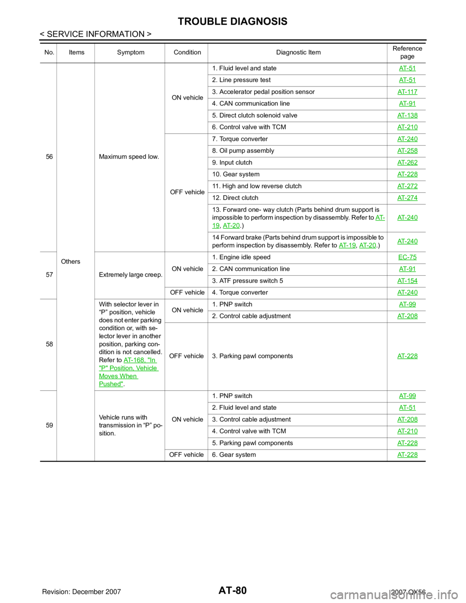
56
OthersMaximum speed low.ON vehicle1. Fluid level and stateAT- 5 1
2. Line pressure testAT- 5 1
3. Accelerator pedal position sensorAT- 11 7
4. CAN communication lineAT- 9 1
5. Direct clutch solenoid valveAT- 1 3 8
6. Control valve with TCMAT- 2 1 0
OFF vehicle7. Torque converterAT- 2 4 0
8. Oil pump assemblyAT- 2 5 8
9. Input clutchAT- 2 6 2
10. Gear systemAT- 2 2 8
11. High and low reverse clutchAT- 2 7 2
12. Direct clutchAT- 2 7 4
13. Forward one- way clutch (Parts behind drum support is
impossible to perform inspection by disassembly. Refer to AT-
19, AT- 2 0.)AT- 2 4 0
14 Forward brake (Parts behind drum support is impossible to
perform inspection by disassembly. Refer to AT- 1 9
, AT- 2 0.)AT- 2 4 0
57 Extremely large creep.ON vehicle1. Engine idle speed EC-75
2. CAN communication lineAT- 9 1
3. ATF pressure switch 5AT- 1 5 4
OFF vehicle 4. Torque converterAT- 2 4 0
58With selector lever in
“P” position, vehicle
does not enter parking
condition or, with se-
lector lever in another
position, parking con-
dition is not cancelled.
Refer to AT-168, "
In
"P" Position, Vehicle
Moves When
Pushed".ON vehicle1. PNP switchAT- 9 9
2. Control cable adjustmentAT- 2 0 8
OFF vehicle 3. Parking pawl componentsAT- 2 2 8
59Vehicle runs with
transmission in “P” po-
sition.ON vehicle1. PNP switchAT- 9 9
2. Fluid level and stateAT- 5 1
3. Control cable adjustmentAT- 2 0 8
4. Control valve with TCMAT- 2 1 0
5. Parking pawl componentsAT- 2 2 8
OFF vehicle 6. Gear systemAT- 2 2 8
No. Items Symptom Condition Diagnostic ItemReference
page
Page 151 of 3061

TROUBLE DIAGNOSIS
AT-81
< SERVICE INFORMATION >
D
E
F
G
H
I
J
K
L
MA
B
AT
N
O
P
60
OthersVehicle runs with
transmission in “N” po-
sition.
Refer to AT- 1 6 9 , "In
"N" Position, Vehicle
Moves".ON vehicle1. PNP switchAT- 9 9
2. Fluid level and stateAT- 5 1
3. Control cable adjustmentAT-208
4. Control valve with TCMAT-210
OFF vehicle5. Input clutchAT-262
6. Gear systemAT-228
7. Direct clutchAT-274
8. Reverse brakeAT-240
9. Forward one- way clutch (Parts behind drum support is im-
possible to perform inspection by disassembly. Refer to AT-
19, AT- 2 0.)AT-240
10. Forward brake (Parts behind drum support is impossible
to perform inspection by disassembly. Refer to AT- 1 9
, AT- 2 0.)AT-240
61Engine does not start
in “N” or “P” position.
Refer to AT- 1 6 8 , "En-
gine Cannot Be Start-
ed in "P" or "N"
Position".ON vehicle1. Ignition switch and starterPG-3
, SC-
9
2. Control cable adjustmentAT-208
3. PNP switchAT- 9 9
62Engine starts in posi-
tions other than “N” or
“P”.ON vehicle1. Ignition switch and starterPG-3
, SC-
9
2. Control cable adjustmentAT-208
3. PNP switchAT- 9 9
63 Engine stall.ON vehicle1. Fluid level and stateAT- 5 1
2. Engine speed signalAT-109
3. Turbine revolution sensorAT-103
4. Torque converter clutch solenoid valveAT- 111
5. CAN communication lineAT- 9 1
6. Control valve with TCMAT-210
OFF vehicle 7. Torque converterAT-240
64Engine stalls when se-
lect lever shifted “N” →
“D”, “R”.ON vehicle1. Fluid level and stateAT- 5 1
2. Engine speed signalAT-109
3. Turbine revolution sensorAT-103
4. Torque converter clutch solenoid valveAT- 111
5. CAN communication lineAT- 9 1
6. Control valve with TCMAT-210
OFF vehicle 7. Torque converterAT-240
No. Items Symptom Condition Diagnostic ItemReference
page
Page 239 of 3061
TROUBLE DIAGNOSIS FOR SYMPTOMS
AT-169
< SERVICE INFORMATION >
D
E
F
G
H
I
J
K
L
MA
B
AT
N
O
P
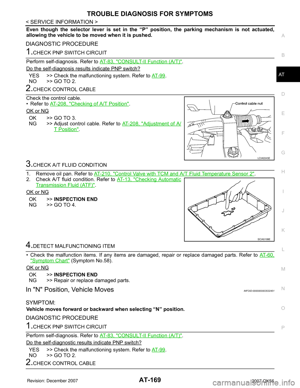
Even though the selector lever is set in the “P” position, the parking mechanism is not actuated,
allowing the vehicle to be moved when it is pushed.
DIAGNOSTIC PROCEDURE
1.CHECK PNP SWITCH CIRCUIT
Perform self-diagnosis. Refer to AT-83, "
CONSULT-II Function (A/T)".
Do the self-diagnosis results indicate PNP switch?
YES >> Check the malfunctioning system. Refer to AT- 9 9.
NO >> GO TO 2.
2.CHECK CONTROL CABLE
Check the control cable.
• Refer to AT-208, "
Checking of A/T Position".
OK or NG
OK >> GO TO 3.
NG >> Adjust control cable. Refer to AT-208, "
Adjustment of A/
T Position".
3.CHECK A/T FLUID CONDITION
1. Remove oil pan. Refer to AT-210, "
Control Valve with TCM and A/T Fluid Temperature Sensor 2".
2. Check A/T fluid condition. Refer to AT-13, "
Checking Automatic
Transmission Fluid (ATF)".
OK or NG
OK >>INSPECTION END
NG >> GO TO 4.
4.DETECT MALFUNCTIONING ITEM
• Check the malfunction items. If any items are damaged, repair or replace damaged parts. Refer to AT-60,
"Symptom Chart" (Symptom No.58).
OK or NG
OK >>INSPECTION END
NG >> Repair or replace damaged parts.
In "N" Position, Vehicle MovesINFOID:0000000003532451
SYMPTOM:
Vehicle moves forward or backward when selecting “N” position.
DIAGNOSTIC PROCEDURE
1.CHECK PNP SWITCH CIRCUIT
Perform self-diagnosis. Refer to AT-83, "
CONSULT-II Function (A/T)".
Do the self-diagnostic results indicate PNP switch?
YES >> Check the malfunctioning system. Refer to AT- 9 9.
NO >> GO TO 2.
2.CHECK CONTROL CABLE
LCIA0345E
SCIA5199E
Page 240 of 3061
AT-170
< SERVICE INFORMATION >
TROUBLE DIAGNOSIS FOR SYMPTOMS
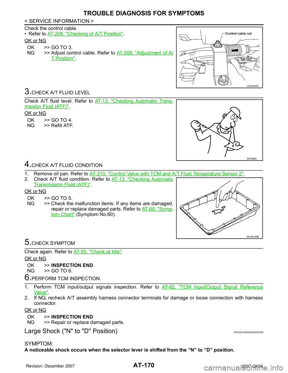
Check the control cable.
• Refer to AT-208, "
Checking of A/T Position".
OK or NG
OK >> GO TO 3.
NG >> Adjust control cable. Refer to AT-208, "
Adjustment of A/
T Position".
3.CHECK A/T FLUID LEVEL
Check A/T fluid level. Refer to AT-13, "
Checking Automatic Trans-
mission Fluid (ATF)".
OK or NG
OK >> GO TO 4.
NG >> Refill ATF.
4.CHECK A/T FLUID CONDITION
1. Remove oil pan. Refer to AT-210, "
Control Valve with TCM and A/T Fluid Temperature Sensor 2".
2. Check A/T fluid condition. Refer to AT-13, "
Checking Automatic
Transmission Fluid (ATF)".
OK or NG
OK >> GO TO 5.
NG >> Check the malfunction items. If any items are damaged,
repair or replace damaged parts. Refer to AT-60, "
Symp-
tom Chart" (Symptom No.60).
5.CHECK SYMPTOM
Check again. Refer to AT-55, "
Check at Idle".
OK or NG
OK >>INSPECTION END
NG >> GO TO 6.
6.PERFORM TCM INSPECTION
1. Perform TCM input/output signals inspection. Refer to AT-82, "
TCM Input/Output Signal Reference
Va l u e".
2. If NG, recheck A/T assembly harness connector terminals for damage or loose connection with harness
connector.
OK or NG
OK >>INSPECTION END
NG >> Repair or replace damaged parts.
Large Shock ("N" to "D" Position)INFOID:0000000003532452
SYMPTOM:
A noticeable shock occurs when the selector lever is shifted from the “N” to “D” position.
LCIA0345E
SAT638A
SCIA5199E
Page 241 of 3061
TROUBLE DIAGNOSIS FOR SYMPTOMS
AT-171
< SERVICE INFORMATION >
D
E
F
G
H
I
J
K
L
MA
B
AT
N
O
P
DIAGNOSTIC PROCEDURE
1.CHECK SELF-DIAGNOSTIC RESULTS
Perform self-diagnosis. Refer to AT-83, "
CONSULT-II Function (A/T)".
Do the self-diagnostic results indicate A/T fluid temperature sensor, engine speed signal, accelerator pedal
position sensor, ATF pressure switch 1, front brake solenoid valve, CAN communication line?
YES >> Check the malfunctioning system. Refer to AT- 11 9, AT-109, AT- 11 7' AT-150' AT-134' AT- 9 1.
NO >> GO TO 2.
2.ENGINE IDLE SPEED
Check the engine idle speed. Refer to EC-75, "
Idle Speed and Ignition Timing Check".
OK or NG
OK >> GO TO 3.
NG >> Repair.
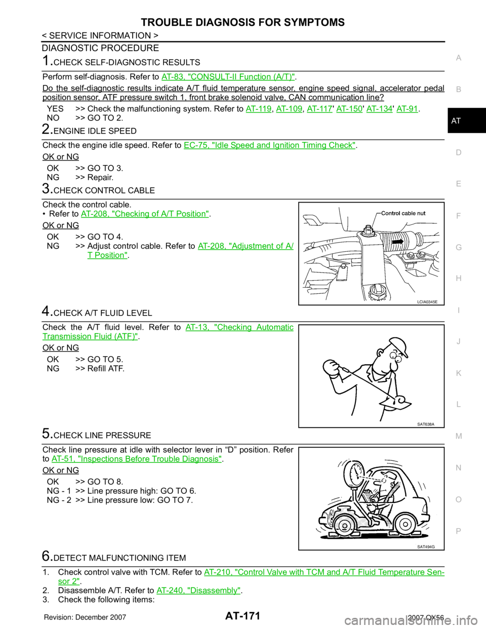
3.CHECK CONTROL CABLE
Check the control cable.
• Refer to AT-208, "
Checking of A/T Position".
OK or NG
OK >> GO TO 4.
NG >> Adjust control cable. Refer to AT-208, "
Adjustment of A/
T Position".
4.CHECK A/T FLUID LEVEL
Check the A/T fluid level. Refer to AT-13, "
Checking Automatic
Transmission Fluid (ATF)".
OK or NG
OK >> GO TO 5.
NG >> Refill ATF.
5.CHECK LINE PRESSURE
Check line pressure at idle with selector lever in “D” position. Refer
to AT-51, "
Inspections Before Trouble Diagnosis".
OK or NG
OK >> GO TO 8.
NG - 1 >> Line pressure high: GO TO 6.
NG - 2 >> Line pressure low: GO TO 7.
6.DETECT MALFUNCTIONING ITEM
1. Check control valve with TCM. Refer to AT-210, "
Control Valve with TCM and A/T Fluid Temperature Sen-
sor 2".
2. Disassemble A/T. Refer to AT-240, "
Disassembly".
3. Check the following items:
LCIA0345E
SAT638A
SAT494G
Page 242 of 3061

AT-172
< SERVICE INFORMATION >
TROUBLE DIAGNOSIS FOR SYMPTOMS
- Oil pump assembly. Refer to AT-258, "Oil Pump".
OK or NG
OK >> GO TO 8.
NG >> Repair or replace damaged parts.
7.DETECT MALFUNCTIONING ITEM
1. Check control valve with TCM. Refer to AT-210, "
Control Valve with TCM and A/T Fluid Temperature Sen-
sor 2".
2. Disassemble A/T. Refer to AT-240, "
Disassembly".
3. Check the following items:
- Oil pump assembly. Refer to AT-258, "
Oil Pump".
- Power train system. Refer to AT-240, "
Disassembly".
- Transmission case. Refer to AT-240, "
Disassembly".
OK or NG
OK >> GO TO 8.
NG >> Repair or replace damaged parts.
8.CHECK A/T FLUID CONDITION
1. Remove oil pan. Refer to AT-210, "
Control Valve with TCM and A/T Fluid Temperature Sensor 2".
2. Check A/T fluid condition. Refer to AT-13, "
Checking Automatic
Transmission Fluid (ATF)".
OK or NG
OK >> GO TO 10.
NG >> GO TO 9.
9.DETECT MALFUNCTIONING ITEM
• Check the malfunction items. If any items are damaged, repair or replace damaged parts. Refer to AT-60,
"Symptom Chart" (Symptom No.1).
OK or NG
OK >> GO TO 10.
NG >> Repair or replace damaged parts.
10.CHECK SYMPTOM
Check again. Refer to AT-55, "
Check at Idle".
OK or NG
OK >>INSPECTION END
NG >> GO TO 11.
11 .PERFORM TCM INSPECTION
1. Perform TCM input/output signals inspection. Refer to AT-82, "
TCM Input/Output Signal Reference
Va l u e".
2. If NG, recheck A/T assembly harness connector terminals for damage or loose connection with harness
connector.
OK or NG
OK >>INSPECTION END
NG >> Repair or replace damaged parts.
Vehicle Does Not Creep Backward in "R" PositionINFOID:0000000003532453
SYMPTOM:
The vehicle does not creep in the “R” position. Or an extreme lack of acceleration is observed.
DIAGNOSTIC PROCEDURE
SCIA5199E