coolant reservoir INFINITI QX56 2007 Factory Service Manual
[x] Cancel search | Manufacturer: INFINITI, Model Year: 2007, Model line: QX56, Model: INFINITI QX56 2007Pages: 3061, PDF Size: 64.56 MB
Page 994 of 3061

PREPARATION
CO-5
< SERVICE INFORMATION >
C
D
E
F
G
H
I
J
K
L
MA
CO
N
P O
Tool nameDescription
Power toolLoosening bolts and nuts
Radiator cap tester Checking radiator and radiator cap
Coolant system tester adapter Adapting radiator cap tester to reservoir filler
neck
Coolant system tester adapter Adapting radiator cap tester to reservoir cap
PBIC0190E
PBIC1982E
WBIA0408E
WBIA0409E
Page 995 of 3061

CO-6
< SERVICE INFORMATION >
OVERHEATING CAUSE ANALYSIS
OVERHEATING CAUSE ANALYSIS
Troubleshooting ChartINFOID:0000000003531566
Symptom Check items
Cooling sys-
tem parts
malfunctionPoor heat transferWater pump malfunction Worn or loose drive belt
— Thermostat stuck closed —
Damaged finsDust contamination or pa-
per clogging
Physical damage
Clogged radiator cooling
tubeExcess foreign material
(rust, dirt, sand, etc.)
Water cut valve malfunctionExcess foreign material
(rust, dirt, sand, etc.), phys-
ical damage
Reduced air flowCooling fan does not oper-
ate
Fan assembly — High resistance to fan rota-
tion
Damaged fan blades
Damaged radiator shroud — — —
Improper engine coolant
mixture ratio———
Poor engine coolant quality — Engine coolant density —
Insufficient engine coolantEngine coolant leaksCooling hoseLoose clamp
Cracked hose
Water pump Poor sealing
Radiator capLoose
Poor sealing
RadiatorO-ring for damage, deterio-
ration or improper fitting
Cracked radiator tank
Cracked radiator core
Reservoir tank Cracked reservoir tank
Overflowing reservoir tankExhaust gas leaks into cool-
ing systemCylinder head deterioration
Cylinder head gasket deteri-
oration
Page 998 of 3061

ENGINE COOLANT
CO-9
< SERVICE INFORMATION >
C
D
E
F
G
H
I
J
K
L
MA
CO
N
P O
ENGINE COOLANT
InspectionINFOID:0000000003531569
LEVEL CHECK
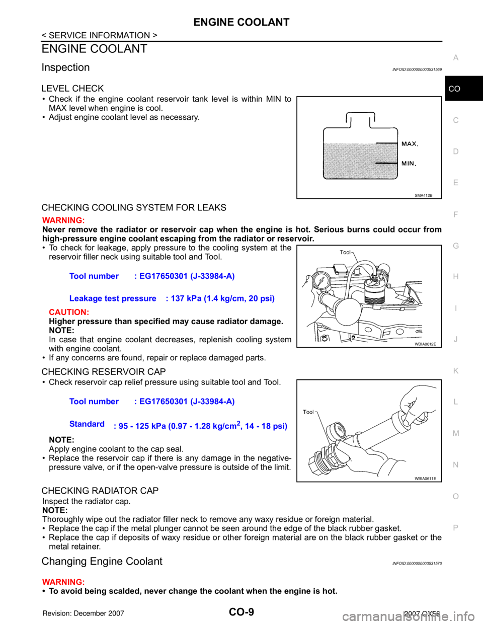
• Check if the engine coolant reservoir tank level is within MIN to
MAX level when engine is cool.
• Adjust engine coolant level as necessary.
CHECKING COOLING SYSTEM FOR LEAKS
WARNING:
Never remove the radiator or reservoir cap when the engine is hot. Serious burns could occur from
high-pressure engine coolant escaping from the radiator or reservoir.
• To check for leakage, apply pressure to the cooling system at the
reservoir filler neck using suitable tool and Tool.
CAUTION:
Higher pressure than specified may cause radiator damage.
NOTE:
In case that engine coolant decreases, replenish cooling system
with engine coolant.
• If any concerns are found, repair or replace damaged parts.
CHECKING RESERVOIR CAP
• Check reservoir cap relief pressure using suitable tool and Tool.
NOTE:
Apply engine coolant to the cap seal.
• Replace the reservoir cap if there is any damage in the negative-
pressure valve, or if the open-valve pressure is outside of the limit.
CHECKING RADIATOR CAP
Inspect the radiator cap.
NOTE:
Thoroughly wipe out the radiator filler neck to remove any waxy residue or foreign material.
• Replace the cap if the metal plunger cannot be seen around the edge of the black rubber gasket.
• Replace the cap if deposits of waxy residue or other foreign material are on the black rubber gasket or the
metal retainer.
Changing Engine CoolantINFOID:0000000003531570
WARNING:
• To avoid being scalded, never change the coolant when the engine is hot.
SMA412B
Tool number : EG17650301 (J-33984-A)
Leakage test pressure : 137 kPa (1.4 kg/cm, 20 psi)
WBIA0612E
Tool number : EG17650301 (J-33984-A)
Standard
: 95 - 125 kPa (0.97 - 1.28 kg/cm
2, 14 - 18 psi)
WBIA0611E
Page 999 of 3061

CO-10
< SERVICE INFORMATION >
ENGINE COOLANT
• Wrap a thick cloth around the cap to carefully remove the cap. First, turn the cap a quarter of a turn
to release any built-up pressure, then push down and turn the cap all the way to remove it.
DRAINING ENGINE COOLANT
1. Turn ignition switch ON and set temperature control lever all the way to HOT position or the highest tem-
perature position. Wait 10 seconds and turn ignition switch OFF.
2. Remove the engine front undercover using power tool.
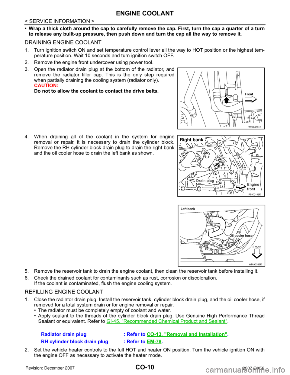
3. Open the radiator drain plug at the bottom of the radiator, and
remove the radiator filler cap. This is the only step required
when partially draining the cooling system (radiator only).
CAUTION:
Do not to allow the coolant to contact the drive belts.
4. When draining all of the coolant in the system for engine
removal or repair, it is necessary to drain the cylinder block.
Remove the RH cylinder block drain plug to drain the right bank
and the oil cooler hose to drain the left bank as shown.
5. Remove the reservoir tank to drain the engine coolant, then clean the reservoir tank before installing it.
6. Check the drained coolant for contaminants such as rust, corrosion or discoloration.
If the coolant is contaminated, flush the engine cooling system.
REFILLING ENGINE COOLANT
1. Close the radiator drain plug. Install the reservoir tank, cylinder block drain plug, and the oil cooler hose, if
removed for a total system drain or for engine removal or repair.
• The radiator must be completely empty of coolant and water.
• Apply sealant to the threads of the cylinder block drain plug. Use Genuine High Performance Thread
Sealant or equivalent. Refer to GI-45, "
Recommended Chemical Product and Sealant".
2. Set the vehicle heater controls to the full HOT and heater ON position. Turn the vehicle ignition ON with
the engine OFF as necessary to activate the heater mode.
WBIA0391E
PBIC0146E
WBIA0392E
Radiator drain plug : Refer to CO-13, "Removal and Installation".
RH cylinder block drain plug : Refer to EM-78
.
Page 1000 of 3061

ENGINE COOLANT
CO-11
< SERVICE INFORMATION >
C
D
E
F
G
H
I
J
K
L
MA
CO
N
P O
3. Remove the vented reservoir cap and replace it with a non-vented reservoir cap before filling the cooling
system.
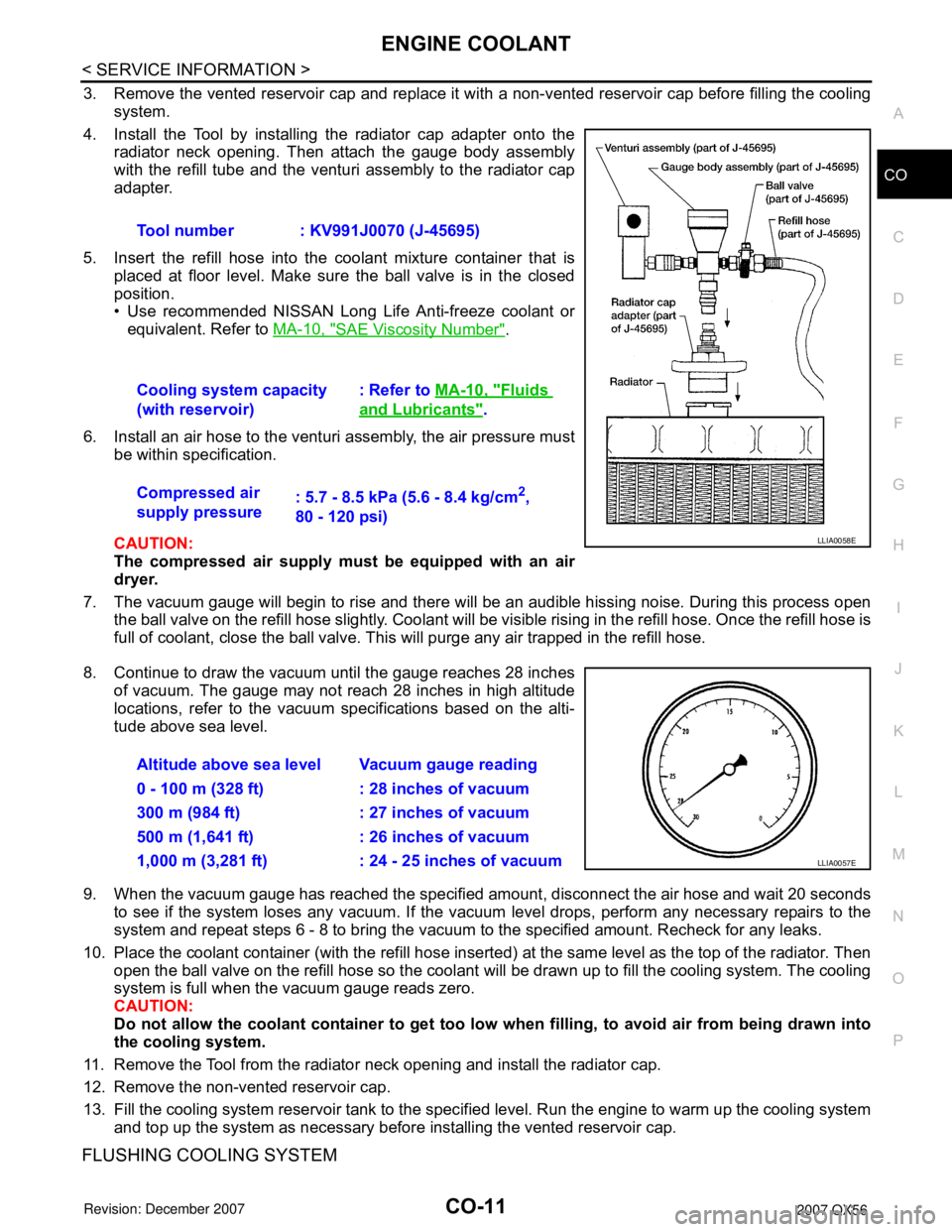
4. Install the Tool by installing the radiator cap adapter onto the
radiator neck opening. Then attach the gauge body assembly
with the refill tube and the venturi assembly to the radiator cap
adapter.
5. Insert the refill hose into the coolant mixture container that is
placed at floor level. Make sure the ball valve is in the closed
position.
• Use recommended NISSAN Long Life Anti-freeze coolant or
equivalent. Refer to MA-10, "
SAE Viscosity Number".
6. Install an air hose to the venturi assembly, the air pressure must
be within specification.
CAUTION:
The compressed air supply must be equipped with an air
dryer.
7. The vacuum gauge will begin to rise and there will be an audible hissing noise. During this process open
the ball valve on the refill hose slightly. Coolant will be visible rising in the refill hose. Once the refill hose is
full of coolant, close the ball valve. This will purge any air trapped in the refill hose.
8. Continue to draw the vacuum until the gauge reaches 28 inches
of vacuum. The gauge may not reach 28 inches in high altitude
locations, refer to the vacuum specifications based on the alti-
tude above sea level.
9. When the vacuum gauge has reached the specified amount, disconnect the air hose and wait 20 seconds
to see if the system loses any vacuum. If the vacuum level drops, perform any necessary repairs to the
system and repeat steps 6 - 8 to bring the vacuum to the specified amount. Recheck for any leaks.
10. Place the coolant container (with the refill hose inserted) at the same level as the top of the radiator. Then
open the ball valve on the refill hose so the coolant will be drawn up to fill the cooling system. The cooling
system is full when the vacuum gauge reads zero.
CAUTION:
Do not allow the coolant container to get too low when filling, to avoid air from being drawn into
the cooling system.
11. Remove the Tool from the radiator neck opening and install the radiator cap.
12. Remove the non-vented reservoir cap.
13. Fill the cooling system reservoir tank to the specified level. Run the engine to warm up the cooling system
and top up the system as necessary before installing the vented reservoir cap.
FLUSHING COOLING SYSTEM
Tool number : KV991J0070 (J-45695)
Cooling system capacity
(with reservoir): Refer to MA-10, "
Fluids
and Lubricants".
Compressed air
supply pressure: 5.7 - 8.5 kPa (5.6 - 8.4 kg/cm
2,
80 - 120 psi)
LLIA0058E
Altitude above sea level Vacuum gauge reading
0 - 100 m (328 ft) : 28 inches of vacuum
300 m (984 ft) : 27 inches of vacuum
500 m (1,641 ft) : 26 inches of vacuum
1,000 m (3,281 ft) : 24 - 25 inches of vacuum
LLIA0057E
Page 1001 of 3061

CO-12
< SERVICE INFORMATION >
ENGINE COOLANT
1. Drain the water from the engine cooling system.
2. Fill the radiator and the reservoir tank (to the “MAX” line), with water. Reinstall the radiator cap and leave
the vented reservoir cap off.
3. Run the engine until it reaches normal operating temperature.
4. Press the engine accelerator two or three times under no-load.
5. Stop the engine and wait until it cools down.
6. Drain the water from the engine cooling system.
7. Repeat steps 2 through 6 until clear water begins to drain from the radiator.
Page 1002 of 3061

RADIATOR
CO-13
< SERVICE INFORMATION >
C
D
E
F
G
H
I
J
K
L
MA
CO
N
P O
RADIATOR
Removal and InstallationINFOID:0000000003531571
WARNING:
Never remove the radiator cap when the engine is hot. Serious burns could occur from high-pressure
engine coolant escaping from the radiator.
REMOVAL
CAUTION:
Perform when the engine is cold.
1. Remove engine room cover. Refer to EM-12, "
Removal and Installation".
2. Drain engine coolant from the radiator. Refer to CO-9, "
Changing Engine Coolant".
3. Remove air cleaner and air duct assembly. Refer to EM-15, "
Removal and Installation".
4. Disconnect A/T fluid cooler hoses.
• Install blind plug to avoid leakage of A/T fluid.
5. Disconnect radiator upper and lower hoses from radiator.
CAUTION:
Do not allow coolant to contact drive belts.
WBIA0694E
1. Radiator 2. Bolt 3. Mounting rubber
4. A/T fluid cooler hose 5. Radiator hose (lower) 6. Air guides
7. Radiator shroud (upper) 8. Radiator shroud (lower) 9. Drain plug
10. Radiator hose (upper) 11. Reservoir tank hose 12. By-pass hose
13. Reservoir tank 14. Reservoir tank cap A. To radiator fill neck
B. To A/T cooler tube C. To water suction pipe D. To thermostat housing
Page 1011 of 3061

CO-22
< SERVICE INFORMATION >
SERVICE DATA AND SPECIFICATIONS (SDS)
SERVICE DATA AND SPECIFICATIONS (SDS)
Standard and LimitINFOID:0000000003531577
ENGINE COOLANT CAPACITY (APPROXIMATE)
Unit: (US gal, Imp gal)
THERMOSTAT
RADIATOR
Unit: kPa (kg/cm2, psi)
Engine coolant capacity with reservoir tank ("MAX" level) 14.4 (3 3/4, 3 1/8)
Valve opening temperature 80 - 84°C (176 - 183°F)
Maximum valve lift More than 10 mm/95°C (0.39 in/203°F)
Valve closing temperature 77°C (171°F) or higher
Reservoir cap relief pressure Standard 95 - 125 (0.97- 1.28, 14 - 18)
Leakage test pressure 137 (1.4, 20)
Page 1180 of 3061

TROUBLE DIAGNOSIS
EC-97
< SERVICE INFORMATION >
C
D
E
F
G
H
I
J
K
L
MA
EC
N
P O
13. Intake valve timing control position
sensor (bank 1) (view with engine
cover and intake air duct removed)14. Intake valve timing control solenoid
valve (bank 2) (view with engine cov-
er and intake air duct removed)15. Drive belt (view with engine cover
and intake air duct removed)
16. Radiator hose (view with engine cov-
er and intake air duct removed)17. Intake valve timing control solenoid
valve (bank 1) (view with engine cov-
er and intake air duct removed)
1. Knock sensor (bank 1) (view with en-
gine removed)2. Knock sensor (bank 2) (view with en-
gine removed)3. Battery current sensor
4. Power steering pressure sensor 5. Power steering fluid reservoir 6. Intake manifold
7. Engine coolant temperature sensor 8. Ignition coils (with power transistor) 9. Ignition coil (with power transistor)
10. Injector harness connectors (bank 2) 11. Injector harness connectors (bank 1)
BBIA0774E
Page 1553 of 3061

EC-470
< SERVICE INFORMATION >
DTC P1217 ENGINE OVER TEMPERATURE
On Board Diagnosis Logic
INFOID:0000000003531991
If the cooling fan or another component in the cooling system malfunctions, engine coolant temperature will
rise.
When the engine coolant temperature reaches an abnormally high temperature condition, a malfunction is
indicated.
This self-diagnosis has the one trip detection logic.
CAUTION:
When a malfunction is indicated, be sure to replace the coolant. Refer to CO-9, "
Changing Engine
Coolant". Also, replace the engine oil. Refer to LU-9, "Changing Engine Oil".
1. Fill radiator with coolant up to specified level with a filling speed of 2 liters per minute. Be sure to
use coolant with the proper mixture ratio. Refer to MA-10, "
SAE Viscosity Number".
2. After refilling coolant, run engine to ensure that no water-flow noise is emitted.
Overall Function CheckINFOID:0000000003531992
Use this procedure to check the overall function of the cooling fan. During this check, a DTC might not be con-
firmed.
WARNING:
Never remove the radiator cap and/or reservoir tank cap when the engine is hot. Serious burns could
be caused by high pressure fluid escaping from the radiator and/or reservoir tank.
Wrap a thick cloth around cap. Carefully remove the cap by turning it a quarter turn to allow built-up
pressure to escape. Then turn the cap all the way off.
WITH CONSULT-II
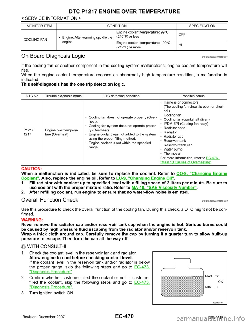
1. Check the coolant level in the reservoir tank and radiator.
Allow engine to cool before checking coolant level.
If the coolant level in the reservoir tank and/or radiator is below
the proper range, skip the following steps and go to EC-473,
"Diagnosis Procedure".
2. Confirm whether customer filled the coolant or not. If customer
filled the coolant, skip the following steps and go to EC-473,
"Diagnosis Procedure".
3. Turn ignition switch ON.
COOLING FAN• Engine: After warming up, idle the
engineEngine coolant temperature: 99°C
(210°F) or lessOFF
Engine coolant temperature: 100°C
(212°F) or moreHI MONITOR ITEM CONDITION SPECIFICATION
DTC No. Trouble diagnosis name DTC detecting condition Possible cause
P1217
1217Engine over tempera-
ture (Overheat)• Cooling fan does not operate properly (Over-
heat).
• Cooling fan system does not operate proper-
ly (Overheat).
• Engine coolant was not added to the system
using the proper filling method.
• Engine coolant is not within the specified
range.• Harness or connectors
(The cooling fan circuit is open or short-
ed.)
• Cooling fan
• Cooling fan (crankshaft diven)
• IPDM E/R (Cooling fan relay)
•Radiator hose
•Radiator
•Radiator cap
• Reservoir tank
• Reservoir tank cap
• Water pump
•Thermostat
For more information, refer to EC-476,
"Main 13 Causes of Overheating".
SEF621W