weight INFINITI QX56 2007 Factory Owner's Manual
[x] Cancel search | Manufacturer: INFINITI, Model Year: 2007, Model line: QX56, Model: INFINITI QX56 2007Pages: 3061, PDF Size: 64.56 MB
Page 1985 of 3061

HOW TO USE THIS MANUAL
GI-19
< SERVICE INFORMATION >
C
D
E
F
G
H
I
J
K
L
MB
GI
N
O
P
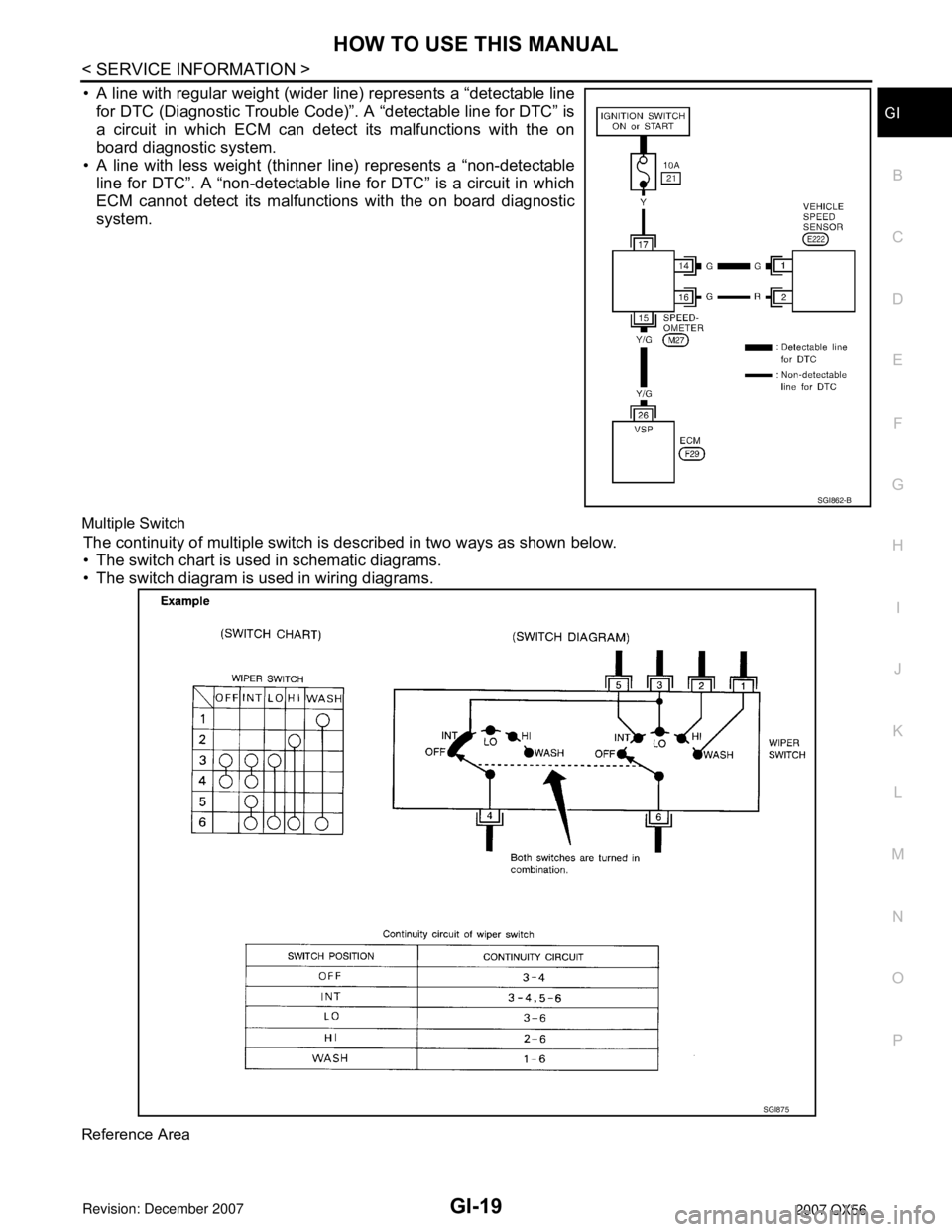
• A line with regular weight (wider line) represents a “detectable line
for DTC (Diagnostic Trouble Code)”. A “detectable line for DTC” is
a circuit in which ECM can detect its malfunctions with the on
board diagnostic system.
• A line with less weight (thinner line) represents a “non-detectable
line for DTC”. A “non-detectable line for DTC” is a circuit in which
ECM cannot detect its malfunctions with the on board diagnostic
system.
Multiple Switch
The continuity of multiple switch is described in two ways as shown below.
• The switch chart is used in schematic diagrams.
• The switch diagram is used in wiring diagrams.
Reference Area
SGI862-B
SGI875
Page 2013 of 3061

IDENTIFICATION INFORMATION
GI-47
< SERVICE INFORMATION >
C
D
E
F
G
H
I
J
K
L
MB
GI
N
O
P
Identification NumberINFOID:0000000003531504
VEHICLE IDENTIFICATION NUMBER ARRANGEMENT
1. Emission control information label 2. Tire placard 3. F.M.V.S.S. certification label
4. Vehicle identification number plate 5. Vacuum hose diagram
WAIA0053E
Position Character Qualifier Definition
1
5N3 Manufacturer 5N3: USA produced multi-purpose vehicle 2
3
4 A Engine type A: VK56DE
5 A Vehicle line A: Infiniti QX56
6 0 Model change (0-9)
7 8 Body type 8: 4 door wagon
8AGross vehicle
weight ratingA: 2WD, 4-wheel ABS, Class E
B: 4WD, 4-wheel ABS, Class E
9 * Check digit(0 to 9 or X) The code for the check digit is determined by a mathematical com-
putation.
10 7 Model year 2007
11 NManufacturing
plantN: Canton Mississippi
12
XXXXXVehicle serial num-
berChassis number 13
14
15
16
17
Page 2228 of 3061

HEADLAMP (FOR USA)
LT-21
< SERVICE INFORMATION >
C
D
E
F
G
H
I
J
L
MA
B
LT
N
O
P
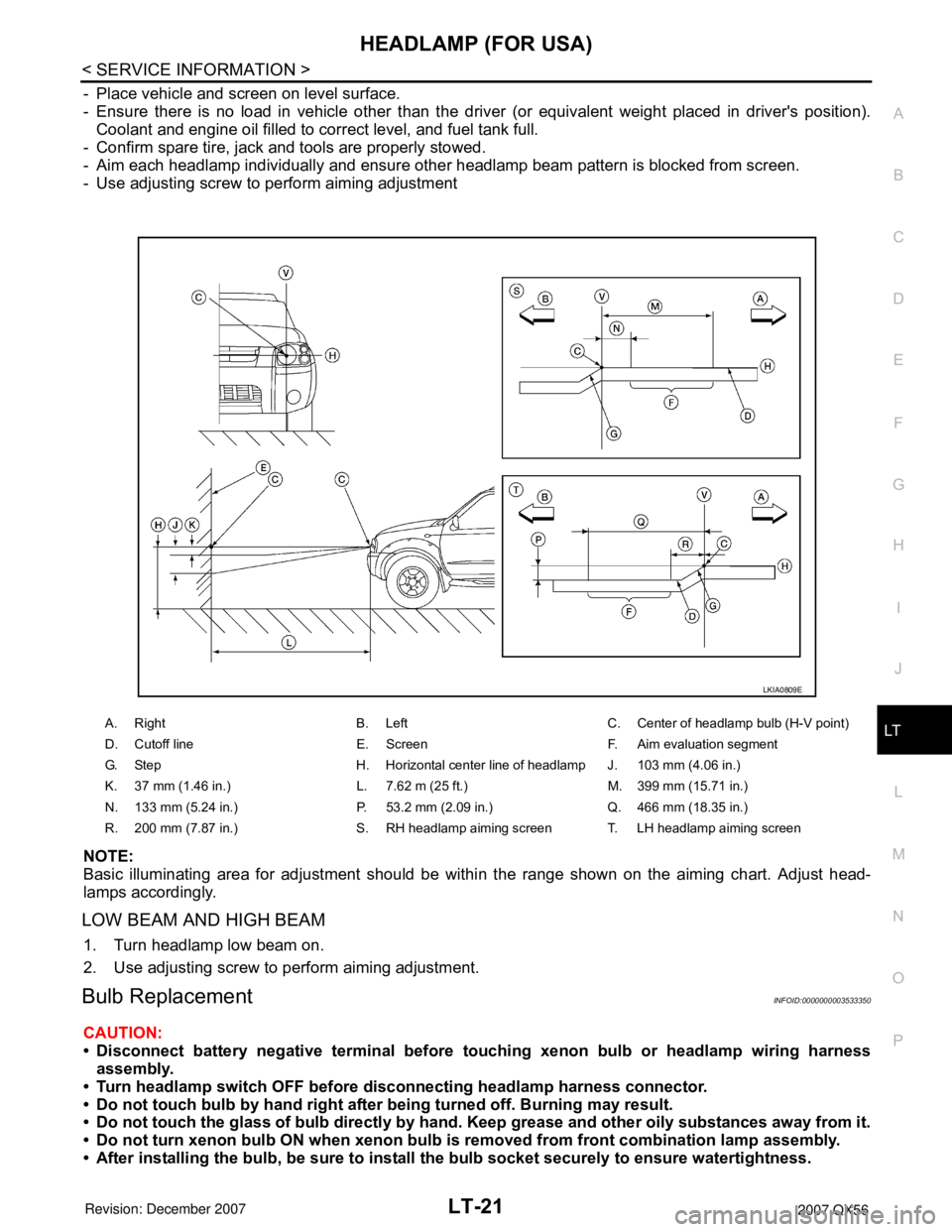
- Place vehicle and screen on level surface.
- Ensure there is no load in vehicle other than the driver (or equivalent weight placed in driver's position).
Coolant and engine oil filled to correct level, and fuel tank full.
- Confirm spare tire, jack and tools are properly stowed.
- Aim each headlamp individually and ensure other headlamp beam pattern is blocked from screen.
- Use adjusting screw to perform aiming adjustment
NOTE:
Basic illuminating area for adjustment should be within the range shown on the aiming chart. Adjust head-
lamps accordingly.
LOW BEAM AND HIGH BEAM
1. Turn headlamp low beam on.
2. Use adjusting screw to perform aiming adjustment.
Bulb ReplacementINFOID:0000000003533350
CAUTION:
• Disconnect battery negative terminal before touching xenon bulb or headlamp wiring harness
assembly.
• Turn headlamp switch OFF before disconnecting headlamp harness connector.
• Do not touch bulb by hand right after being turned off. Burning may result.
• Do not touch the glass of bulb directly by hand. Keep grease and other oily substances away from it.
• Do not turn xenon bulb ON when xenon bulb is removed from front combination lamp assembly.
• After installing the bulb, be sure to install the bulb socket securely to ensure watertightness.
A. Right B. Left C. Center of headlamp bulb (H-V point)
D. Cutoff line E. Screen F. Aim evaluation segment
G. Step H. Horizontal center line of headlamp J. 103 mm (4.06 in.)
K. 37 mm (1.46 in.) L. 7.62 m (25 ft.) M. 399 mm (15.71 in.)
N. 133 mm (5.24 in.) P. 53.2 mm (2.09 in.) Q. 466 mm (18.35 in.)
R. 200 mm (7.87 in.) S. RH headlamp aiming screen T. LH headlamp aiming screen
LKIA0809E
Page 2262 of 3061

FRONT FOG LAMP
LT-55
< SERVICE INFORMATION >
C
D
E
F
G
H
I
J
L
MA
B
LT
N
O
P
Aiming AdjustmentINFOID:0000000003533400
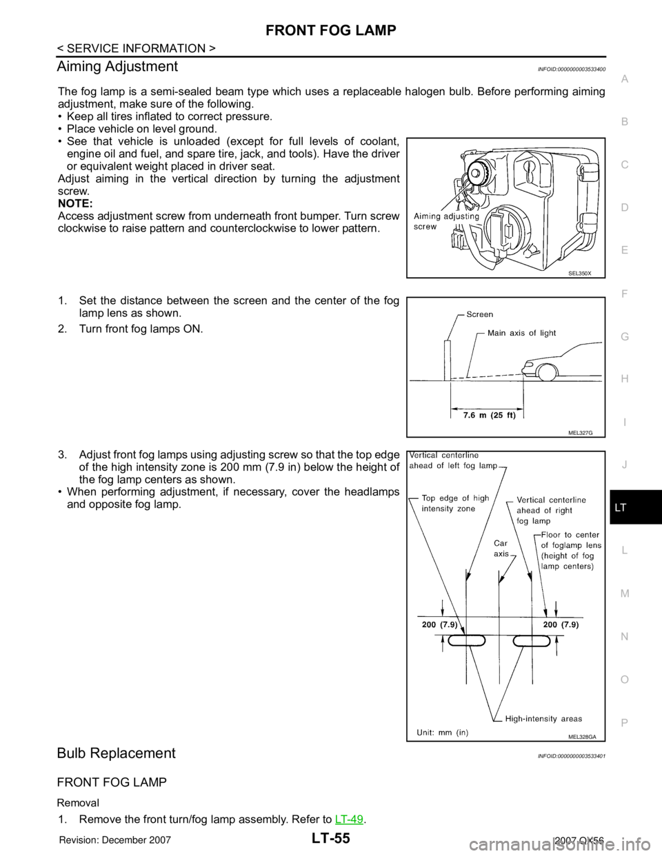
The fog lamp is a semi-sealed beam type which uses a replaceable halogen bulb. Before performing aiming
adjustment, make sure of the following.
• Keep all tires inflated to correct pressure.
• Place vehicle on level ground.
• See that vehicle is unloaded (except for full levels of coolant,
engine oil and fuel, and spare tire, jack, and tools). Have the driver
or equivalent weight placed in driver seat.
Adjust aiming in the vertical direction by turning the adjustment
screw.
NOTE:
Access adjustment screw from underneath front bumper. Turn screw
clockwise to raise pattern and counterclockwise to lower pattern.
1. Set the distance between the screen and the center of the fog
lamp lens as shown.
2. Turn front fog lamps ON.
3. Adjust front fog lamps using adjusting screw so that the top edge
of the high intensity zone is 200 mm (7.9 in) below the height of
the fog lamp centers as shown.
• When performing adjustment, if necessary, cover the headlamps
and opposite fog lamp.
Bulb ReplacementINFOID:0000000003533401
FRONT FOG LAMP
Removal
1. Remove the front turn/fog lamp assembly. Refer to LT- 4 9.
SEL350X
MEL327G
MEL328GA
Page 2361 of 3061

LU-16
< SERVICE INFORMATION >
OIL PUMP
• (Clearance) = (Inner diameter of oil pump body) - (Outer diameter of inner rotor)
Regulator Valve Clearance
Check regulator valve to oil pump cover clearance using the following formula.
• (Clearance) = D
1 (Valve hole diameter) - D2 (Outer Diameter of
valve)
CAUTION:
• Coat regulator valve with engine oil.
• Check that it falls smoothly into the regulator valve hole by its
own weight.
ASSEMBLY
Installation is in the reverse order of removal.
NOTE:
Install the inner rotor and outer rotor with the punched marks on the
oil pump cover side.Inner rotor to brazed portion of housing
clearance
: 0.045 - 0.091 mm (0.0018 - 0.0036 in)
Regulator valve to oil pump cover
: 0.040 - 0.097 mm (0.0016 - 0.0038 in)
PBIC0143E
PBIC0144E
Page 2388 of 3061

MA-26
< SERVICE INFORMATION >
CHASSIS AND BODY MAINTENANCE
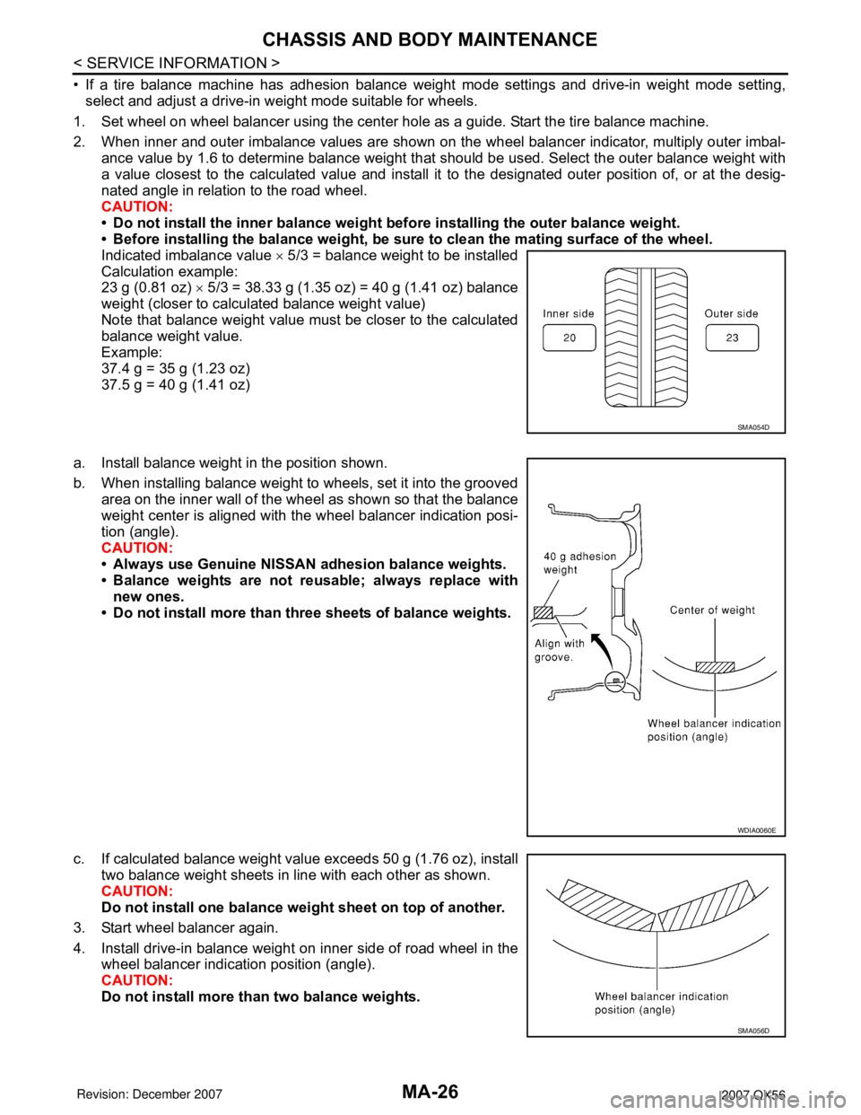
• If a tire balance machine has adhesion balance weight mode settings and drive-in weight mode setting,
select and adjust a drive-in weight mode suitable for wheels.
1. Set wheel on wheel balancer using the center hole as a guide. Start the tire balance machine.
2. When inner and outer imbalance values are shown on the wheel balancer indicator, multiply outer imbal-
ance value by 1.6 to determine balance weight that should be used. Select the outer balance weight with
a value closest to the calculated value and install it to the designated outer position of, or at the desig-
nated angle in relation to the road wheel.
CAUTION:
• Do not install the inner balance weight before installing the outer balance weight.
• Before installing the balance weight, be sure to clean the mating surface of the wheel.
Indicated imbalance value × 5/3 = balance weight to be installed
Calculation example:
23 g (0.81 oz) × 5/3 = 38.33 g (1.35 oz) = 40 g (1.41 oz) balance
weight (closer to calculated balance weight value)
Note that balance weight value must be closer to the calculated
balance weight value.
Example:
37.4 g = 35 g (1.23 oz)
37.5 g = 40 g (1.41 oz)
a. Install balance weight in the position shown.
b. When installing balance weight to wheels, set it into the grooved
area on the inner wall of the wheel as shown so that the balance
weight center is aligned with the wheel balancer indication posi-
tion (angle).
CAUTION:
• Always use Genuine NISSAN adhesion balance weights.
• Balance weights are not reusable; always replace with
new ones.
• Do not install more than three sheets of balance weights.
c. If calculated balance weight value exceeds 50 g (1.76 oz), install
two balance weight sheets in line with each other as shown.
CAUTION:
Do not install one balance weight sheet on top of another.
3. Start wheel balancer again.
4. Install drive-in balance weight on inner side of road wheel in the
wheel balancer indication position (angle).
CAUTION:
Do not install more than two balance weights.
SMA054D
WDIA0060E
SMA056D
Page 2995 of 3061

WT-6
< SERVICE INFORMATION >
WHEEL AND TIRE ASSEMBLY
WHEEL AND TIRE ASSEMBLY
Balancing WheelsINFOID:0000000003532690
Removal
1. Using releasing agent, remove double-faced adhesive tape from the wheel.
CAUTION:
• Be careful not to scratch the wheel during removal.
• After removing double-faced adhesive tape, wipe clean traces of releasing agent from the wheel.
Wheel Balance Adjustment
• If a tire balance machine has adhesion balance weight mode settings and drive-in weight mode setting,
select and adjust a drive-in weight mode suitable for wheels.
1. Set wheel on wheel balancer using the center hole as a guide. Start the tire balance machine.
2. When inner and outer imbalance values are shown on the wheel balancer indicator, multiply outer imbal-
ance value by 1.6 to determine balance weight that should be used. Select the outer balance weight with
a value closest to the calculated value and install it to the designated outer position of, or at the desig-
nated angle in relation to the road wheel.
CAUTION:
• Do not install the inner balance weight before installing the outer balance weight.
• Before installing the balance weight, be sure to clean the mating surface of the wheel.
Indicated imbalance value × 5/3 = balance weight to be installed
Calculation example:
23 g (0.81 oz) × 5/3 = 38.33 g (1.35 oz) = 40 g (1.41 oz) balance
weight (closer to calculated balance weight value)
Note that balance weight value must be closer to the calculated
balance weight value.
Example:
37.4 g = 35 g (1.23 oz)
37.5 g = 40 g (1.41 oz)
a. Install balance weight in the position shown.
b. When installing balance weight to wheels, set it into the grooved
area on the inner wall of the wheel as shown so that the balance
weight center is aligned with the wheel balancer indication posi-
tion (angle).
CAUTION:
• Always use Genuine NISSAN adhesion balance weights.
• Balance weights are not reusable; always replace with
new ones.
• Do not install more than three sheets of balance weights.
SMA054D
WDIA0060E
Page 2996 of 3061

WHEEL AND TIRE ASSEMBLY
WT-7
< SERVICE INFORMATION >
C
D
F
G
H
I
J
K
L
MA
B
WT
N
O
P
c. If calculated balance weight value exceeds 50 g (1.76 oz), install
two balance weight sheets in line with each other as shown.
CAUTION:
Do not install one balance weight sheet on top of another.
3. Start wheel balancer again.
4. Install drive-in balance weight on inner side of road wheel in the
wheel balancer indication position (angle).
CAUTION:
Do not install more than two balance weights.
5. Start wheel balancer. Make sure that inner and outer residual
imbalance values are 5 g (0.18 oz) each or below.
• If either residual imbalance value exceeds 5 g (0.18 oz),
repeat installation procedures.
Wheel balance (Maximum allowable imbalance):
RotationINFOID:0000000003532691
NOTE:
Follow the maintenance schedule for tire rotation service intervals. Refer to MA-6
.
1. Rotate the tires on each side from front to back as shown. Do
not include the spare tire when rotating the tires.
CAUTION:
When installing wheels, tighten them diagonally by dividing
the work two to three times in order to prevent the wheels
from developing any distortion.
2. Adjust the tire pressure to specification. Refer to WT-28, "
Tire" .
3. After the tire rotation, retighten the wheel nuts after the vehicle
has been driven for 1,000 km (600 miles), and also after every
wheel and tire have been installed such as after repairing a flat tire.
Maximum allowable imbalanceDynamic (At rim flange) 5 g (0.18 oz) (one side)
Static 10 g (0.35 oz)
SMA056D
Wheel nut torque : 133 N·m (14 kg-m, 98 ft-lb)
SMA829C