service INFINITI QX56 2007 Factory Service Manual
[x] Cancel search | Manufacturer: INFINITI, Model Year: 2007, Model line: QX56, Model: INFINITI QX56 2007Pages: 3061, PDF Size: 64.56 MB
Page 390 of 3061

ATC-20
< SERVICE INFORMATION >
OIL
OIL
Maintenance of Oil Quantity in CompressorINFOID:0000000003533232
The oil in the compressor circulates through the system with the refrigerant. Add oil to compressor when
replacing any component or after a large refrigerant leakage has occurred. It is important to maintain the spec-
ified amount.
If oil quantity is not maintained properly, the following malfunctions may result:
• Lack of oil: May lead to a seized compressor
• Excessive oil: Inadequate cooling (thermal exchange interference)
OIL
Name: NISSAN A/C System Oil Type S or equivalent
CHECKING AND ADJUSTING
CAUTION:
If excessive oil leakage is noted, do no t perform the oil return operation.
Start the engine and set the following conditions:
Test Condition
• Engine speed: Idling to 1,200 rpm
• A/C switch: On
• Blower fan speed: MAX position
• Temp. control: Optional [Set so that intake air temperature is 25 ° to 30 ° C (77 ° to 86 °F)]
• Intake position: Recirculation ( )
• Perform oil return operation for about ten minutes
Adjust the oil quantity according to the following table.
Oil Adjusting Procedure for Components Replacement Except Compressor
After replacing any of the following major component s, add the correct amount of oil to the system.
Amount of oil to be added :
• *1: If refrigerant leak is small, no addition of oil is needed.
Oil Adjustment Procedure for Compressor Replacement
Part replaced Oil to be added to system
Remarks
Amount of oil
m (US fl oz, Imp fl oz)
Front evaporator 75 (2.5, 2.6) —
Rear evaporator 75 (2.5, 2.6) —
Condenser 75 (2.5, 2.6) —
Liquid tank 5 (0.2, 0.2) Add if compressor is not replaced.
In case of refrigerant leak 30 (1.0, 1.1) Large leak
— Small leak *1
Page 391 of 3061

OIL
ATC-21
< SERVICE INFORMATION >
C
D E
F
G H
I
K L
M A
B
AT C
N
O P
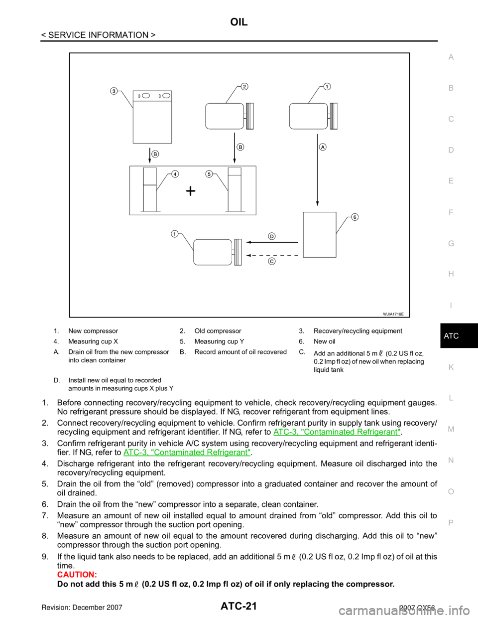
1. Before connecting recovery/recycling equipment to vehicle, check recovery/recycling equipment gauges.
No refrigerant pressure should be displayed. If NG, recover refrigerant from equipment lines.
2. Connect recovery/recycling equipment to vehicle. Confir m refrigerant purity in supply tank using recovery/
recycling equipment and refrigerant identifier. If NG, refer to AT C - 3 , "
Contaminated Refrigerant".
3. Confirm refrigerant purity in vehicle A/C system using recovery/recycling equipment and refrigerant identi-
fier. If NG, refer to AT C - 3 , "
Contaminated Refrigerant".
4. Discharge refrigerant into the refrigerant recove ry/recycling equipment. Measure oil discharged into the
recovery/recycling equipment.
5. Drain the oil from the “old” (removed) compress or into a graduated container and recover the amount of
oil drained.
6. Drain the oil from the “new” compressor into a separate, clean container.
7. Measure an amount of new oil installed equal to am ount drained from “old” compressor. Add this oil to
“new” compressor through the suction port opening.
8. Measure an amount of new oil equal to the amount recovered during discharging. Add this oil to “new” compressor through the suction port opening.
9. If the liquid tank also needs to be replaced, add an additional 5 m (0.2 US fl oz, 0.2 Imp fl oz) of oil at this
time.
CAUTION:
Do not add this 5 m (0.2 US fl oz, 0.2 Imp fl oz) of oil if only replacing the compressor.
1. New compressor 2. Old compressor 3. Recovery/recycling equipment
4. Measuring cup X 5. Measuring cup Y 6. New oil
A. Drain oil from the new compressor
into clean container B. Record amount of oil recovered C.
Add an additional 5 m (0.2 US fl oz,
0.2 Imp fl oz) of new oil when replacing
liquid tank
D. Install new oil equal to recorded amounts in measuring cups X plus Y
WJIA1716E
Page 392 of 3061

ATC-22
< SERVICE INFORMATION >
AIR CONDITIONER CONTROL
AIR CONDITIONER CONTROL
DescriptionINFOID:0000000003533233
The front air control provides automatic regulation of the vehicle's interior temperature. The system is based
on the driver's and passenger's selected "set temperat ure", regardless of the outside temperature changes.
This is done by utilizing a microcomputer, also referred to as the front air control, which receives input signals
from the following seven sensors:
• Ambient sensor
• In-vehicle sensor
• Intake sensor
• Optical sensor (providing one input for driver and one input for passenger side)
• PBR (Position Balanced Resistor)
• Vehicle speed sensor (via CAN communication)
• Engine coolant temperature (via CAN communication)
The front air control uses these signals (including the set temperature) to automatically control:
• Outlet air volume
• Air temperature
• Air distribution
The front air control also provides separate regulation of the vehicle's interior temperature for the rear passen-
ger area. The system is based on the temperature and r ear blower settings selected from rear control
switches located on the front air control, or from the temperature and rear blower settings selected from rear
control switches on the rear air control, when the front air control switches are set to the rear position.
The front air control is used to select: • Outlet air volume
• Air temperature/distribution
OperationINFOID:0000000003533234
AIR MIX DOORS CONTROL
The air mix doors are automatically controlled so that in-vehicle temperature is maintained at a predetermined
value by the temperature setting, ambient temper ature, in-vehicle temperature and amount of sunload.
BLOWER SPEED CONTROL
Blower speed is automatically controlled by the temperat ure setting, ambient temperature, in-vehicle tempera-
ture, intake temperature, amount of sunload and air mix door position.
When AUTO switch is pressed, the blower motor starts to gradually increase air flow volume (if required).
When engine coolant temperature is low, the blower moto r operation is delayed to prevent cool air from flow-
ing.
INTAKE DOOR CONTROL
The intake door is automatically controlled by the tem perature setting, ambient temperature, in-vehicle tem-
perature, intake temperature, amount of sunl oad and by the ON-OFF operation of the compressor.
MODE DOOR CONTROL
The mode door is automatically controlled by the temperat ure setting, ambient temperature, in-vehicle temper-
ature, intake temperature and amount of sunload.
DEFROSTER DOOR CONTROL
The defroster door is controlled by: Turning the defroster dial to front defroster.
Page 393 of 3061

AIR CONDITIONER CONTROLATC-23
< SERVICE INFORMATION >
C
DE
F
G H
I
K L
M A
B
AT C
N
O P
MAGNET CLUTCH CONTROL
When A/C switch or DEF switch is pressed, front air control inputs compressor ON signal to BCM.
BCM sends compressor ON signal to ECM and front air control via CAN communication line.
ECM judges whether compressor can be turned ON, based on each sensor status (refrigerant pressure sen-
sor signal, throttle angle sensor, etc.). If it judges compressor can be turned ON, it sends compressor ON sig-
nal to IPDM E/R, via CAN communication line.
Upon receipt of compressor ON signal from ECM, IPDM E/R turns air conditioner relay ON to operate com-
pressor.
SELF-DIAGNOSTIC SYSTEM
The self-diagnostic system is built into the front air cont rol to quickly locate the cause of symptoms. Refer to
ATC-48, "
A/C System Self-Diagnosis Function"
Description of Control SystemINFOID:0000000003533235
The control system consists of input sensors, swit ches, the front air control (microcomputer) and outputs.
WJIA2144E
Page 394 of 3061

ATC-24
< SERVICE INFORMATION >
AIR CONDITIONER CONTROL
The relationship of these components is shown in the figure below:
Control OperationINFOID:0000000003533236
Front air control
DISPLAY SCREEN
Displays the operational status of the system.
AUTO SWITCH
• The compressor, intake door, air mix doors, outlet doors and blower speed are automatically controlled so
that the in-vehicle temperature will reach, and be mainta ined at the set temperature selected by the operator.
• When pressing AUTO switch, air inlet, air outlet, bl ower speed, and discharge air temperature are automati-
cally controlled.
WJIA1917E
WJIA1714E
Page 395 of 3061

AIR CONDITIONER CONTROLATC-25
< SERVICE INFORMATION >
C
DE
F
G H
I
K L
M A
B
AT C
N
O P
TEMPERATURE CONTROL DIAL (TEMPE RATURE CONTROL) (DRIVER SIDE)
Increases or decreases the set temperature.
TEMPERATURE CONTROL DIAL (TEMPERATURE CONTROL) (PASSENGER SIDE)
Increases or decreases the set temperature.
TEMPERATURE CONTROL DIAL (TEMPERA TURE AND MODE CONTROL) (REAR)
Increases or decreases the set temperature. The mode al so changes from foot at full hot setting, to foot/vent
mid-range (warm) setting, and then to panel on full cold setting.
RECIRCULATION ( ) SWITCH
• When REC switch is ON, REC switch indicator turns ON, and air inlet is set to REC.
• When REC switch is turned OFF, or when compressor is turned from ON to OFF, REC switch is automati-
cally turned OFF. REC mode can be re-entered by pressing REC switch again.
• REC switch is not operated when DEF switch is tu rned ON, at the D/F position or in floor position.
DEFROSTER ( ) SWITCH
Positions the air outlet doors to the defrost position. Al so positions the intake doors to the outside air position.
REAR WINDOW DEFOGGER SWITCH
When switch is ON, rear window and door mirrors are defogged.
OFF SWITCH
The compressor and blower are OFF, the intake doors are set to the outside air position, and the air outlet
doors are set to the foot (75% foot and 25% defrost) position.
A/C SWITCH
The compressor is ON or OFF.
(Pressing the A/C switch when the AUTO switch is ON will turn off the A/C switch and compressor.)
MODE SWITCH (FRONT)
Controls the air discharge outlets.
FRONT BLOWER CONTROL DIAL
Manually control the blower speed. Seven speeds are av ailable for manual control (as shown on the display
screen).
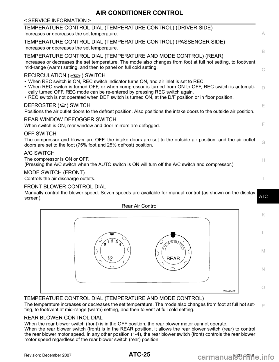
Rear Air Control
TEMPERATURE CONTROL DIAL (TEM PERATURE AND MODE CONTROL)
The temperature increases or decreases the set temperat ure. The mode also changes from foot at full hot set-
ting, to foot/vent at mid-range (warm) setti ng, and then to vent at full cold setting.
REAR BLOWER CONTROL DIAL
When the rear blower switch (front) is in the OFF position, the rear blower motor cannot operate.
When the rear blower switch (front) is in the REAR positi on, it allows the rear blower switch (rear) to control
the rear blower motor speed. In any other position (1-4), the rear blower switch (front) controls the rear blower
motor speed regardless of the rear blower switch (rear) position.
WJIA1042E
Page 396 of 3061

ATC-26
< SERVICE INFORMATION >
AIR CONDITIONER CONTROL
Discharge Air Flow
INFOID:0000000003533237
FRONT
REAR
WJIA0540E
WJIA0528E
WJIA0541E
Page 397 of 3061

AIR CONDITIONER CONTROLATC-27
< SERVICE INFORMATION >
C
DE
F
G H
I
K L
M A
B
AT C
N
O P
System Description (Front)INFOID:0000000003533238
SWITCHES AND THEIR CONTROL FUNCTION
WJIA1236E
WJIA1680E
Page 398 of 3061

ATC-28
< SERVICE INFORMATION >
AIR CONDITIONER CONTROL
System Description (Rear)
INFOID:0000000003533239
SWITCHES AND THEIR CONTROL FUNCTION
WJIA1237E
WJIA0623E
Page 399 of 3061

AIR CONDITIONER CONTROLATC-29
< SERVICE INFORMATION >
C
DE
F
G H
I
K L
M A
B
AT C
N
O P
CAN Communication System DescriptionINFOID:0000000003533240
Refer to LAN-4.
WJIA1067E