brake INFINITI QX56 2007 Factory Owner's Guide
[x] Cancel search | Manufacturer: INFINITI, Model Year: 2007, Model line: QX56, Model: INFINITI QX56 2007Pages: 3061, PDF Size: 64.56 MB
Page 73 of 3061

AT-3
D
E
F
G
H
I
J
K
L
MA
B
AT
N
O
P N On Board Diagnosis Logic ....................................
128
Possible Cause .....................................................128
DTC Confirmation Procedure ................................128
Diagnosis Procedure .............................................128
DTC P1752 INPUT CLUTCH SOLENOID
VALVE ..............................................................
130
Description ............................................................130
CONSULT-II Reference Value in Data Monitor
Mode .....................................................................
130
On Board Diagnosis Logic ....................................130
Possible Cause .....................................................130
DTC Confirmation Procedure ................................130
Diagnosis Procedure .............................................130
DTC P1754 INPUT CLUTCH SOLENOID
VALVE FUNCTION ..........................................
132
Description ............................................................132
CONSULT-II Reference Value in Data Monitor
Mode .....................................................................
132
On Board Diagnosis Logic ....................................132
Possible Cause .....................................................132
DTC Confirmation Procedure ................................132
Diagnosis Procedure .............................................133
DTC P1757 FRONT BRAKE SOLENOID
VALVE ..............................................................
134
Description ............................................................134
CONSULT-II Reference Value in Data Monitor
Mode .....................................................................
134
On Board Diagnosis Logic ....................................134
Possible Cause .....................................................134
DTC Confirmation Procedure ................................134
Diagnosis Procedure .............................................134
DTC P1759 FRONT BRAKE SOLENOID
VALVE FUNCTION ..........................................
136
Description ............................................................136
CONSULT-II Reference Value in Data Monitor
Mode .....................................................................
136
On Board Diagnosis Logic ....................................136
Possible Cause .....................................................136
DTC Confirmation Procedure ................................136
Diagnosis Procedure .............................................137
DTC P1762 DIRECT CLUTCH SOLENOID
VALVE ..............................................................
138
Description ............................................................138
CONSULT-II Reference Value in Data Monitor
Mode .....................................................................
138
On Board Diagnosis Logic ....................................138
Possible Cause .....................................................138
DTC Confirmation Procedure ................................138
Diagnosis Procedure .............................................138
DTC P1764 DIRECT CLUTCH SOLENOID
VALVE FUNCTION ..........................................
140
Description ............................................................140
CONSULT-II Reference Value in Data Monitor
Mode .....................................................................
140
On Board Diagnosis Logic .....................................140
Possible Cause ......................................................140
DTC Confirmation Procedure ................................140
Diagnosis Procedure .............................................141
DTC P1767 HIGH AND LOW REVERSE
CLUTCH SOLENOID VALVE .........................
142
Description .............................................................142
CONSULT-II Reference Value in Data Monitor
Mode ......................................................................
142
On Board Diagnosis Logic .....................................142
Possible Cause ......................................................142
DTC Confirmation Procedure ................................142
Diagnosis Procedure .............................................142
DTC P1769 HIGH AND LOW REVERSE
CLUTCH SOLENOID VALVE FUNCTION ......
144
Description .............................................................144
CONSULT-II Reference Value in Data Monitor
Mode ......................................................................
144
On Board Diagnosis Logic .....................................144
Possible Cause ......................................................144
DTC Confirmation Procedure ................................144
Diagnosis Procedure .............................................145
DTC P1772 LOW COAST BRAKE SOLENOID
VALVE .............................................................
146
Description .............................................................146
CONSULT-II Reference Value in Data Monitor
Mode ......................................................................
146
On Board Diagnosis Logic .....................................146
Possible Cause ......................................................146
DTC Confirmation Procedure ................................146
Diagnosis Procedure .............................................146
DTC P1774 LOW COAST BRAKE SOLENOID
VALVE FUNCTION .........................................
148
Description .............................................................148
CONSULT-II Reference Value in Data Monitor
Mode ......................................................................
148
On Board Diagnosis Logic .....................................148
Possible Cause ......................................................148
DTC Confirmation Procedure ................................148
Diagnosis Procedure .............................................149
DTC P1841 ATF PRESSURE SWITCH 1 .......150
Description .............................................................150
CONSULT-II Reference Value in Data Monitor
Mode ......................................................................
150
On Board Diagnosis Logic .....................................150
Possible Cause ......................................................150
DTC Confirmation Procedure ................................150
Diagnosis Procedure .............................................150
DTC P1843 ATF PRESSURE SWITCH 3 .......152
Description .............................................................152
CONSULT-II Reference Value in Data Monitor
Mode ......................................................................
152
On Board Diagnosis Logic .....................................152
Possible Cause ......................................................152
Page 74 of 3061

AT-4
DTC Confirmation Procedure ................................152
Diagnosis Procedure .............................................152
DTC P1845 ATF PRESSURE SWITCH 5 ........154
Description .............................................................154
CONSULT-II Reference Value in Data Monitor
Mode ......................................................................
154
On Board Diagnosis Logic .....................................154
Possible Cause ......................................................154
DTC Confirmation Procedure ................................154
Diagnosis Procedure .............................................154
DTC P1846 ATF PRESSURE SWITCH 6 ........156
Description .............................................................156
CONSULT-II Reference Value in Data Monitor
Mode ......................................................................
156
On Board Diagnosis Logic .....................................156
Possible Cause ......................................................156
DTC Confirmation Procedure ................................156
Diagnosis Procedure .............................................156
MAIN POWER SUPPLY AND GROUND CIR-
CUIT .................................................................
158
Wiring Diagram - AT - MAIN ..................................158
Diagnosis Procedure .............................................159
CLOSED THROTTLE POSITION AND WIDE
OPEN THROTTLE POSITION CIRCUIT .........
161
CONSULT-II Reference Value in Data Monitor
Mode ......................................................................
161
Diagnosis Procedure .............................................161
BRAKE SIGNAL CIRCUIT ..............................162
CONSULT-II Reference Value in Data Monitor
Mode ......................................................................
162
Diagnosis Procedure .............................................162
TOW MODE SWITCH ......................................163
Description .............................................................163
Wiring Diagram - AT - TMSW ................................163
Diagnosis Procedure .............................................164
TROUBLE DIAGNOSIS FOR SYMPTOMS .....165
Wiring Diagram - AT - NONDTC ............................165
A/T Check Indicator Lamp Does Not Come On .....167
Engine Cannot Be Started in "P" or "N" Position ...168
In "P" Position, Vehicle Moves When Pushed .......168
In "N" Position, Vehicle Moves ..............................169
Large Shock ("N" to "D" Position) ..........................170
Vehicle Does Not Creep Backward in "R" Position ..172
Vehicle Does Not Creep Forward in "D" Position ..175
Vehicle Cannot Be Started from D1 .......................177
A/T Does Not Shift: D1→ D2 ..................................179
A/T Does Not Shift: D2→ D3 ..................................181
A/T Does Not Shift: D3→ D4 ..................................183
A/T Does Not Shift: D4→ D5 ..................................185
A/T Does Not Perform Lock-up .............................187
A/T Does Not Hold Lock-up Condition ...................189
Lock-up Is Not Released .......................................190
Engine Speed Does Not Return to Idle .................191
A/T Does Not Shift: 5th gear → 4th gear ..............192
A/T Does Not Shift: 4th gear → 3rd gear ..............194
A/T Does Not Shift: 3rd gear → 2nd gear .............196
A/T Does Not Shift: 2nd gear → 1st gear .............197
Vehicle Does Not Decelerate By Engine Brake ....199
A/T SHIFT LOCK SYSTEM ..............................202
Description ............................................................202
Shift Lock System Electrical Parts Location ..........202
Wiring Diagram - AT - SHIFT ................................203
Shift Lock Control Unit Reference Value ..............204
Component Inspection ..........................................204
SHIFT CONTROL SYSTEM .............................207
Control Device Removal and Installation ..............207
Adjustment of A/T Position ....................................208
Checking of A/T Position .......................................208
ON-VEHICLE SERVICE ...................................209
Oil Pan ..................................................................209
Control Valve with TCM and A/T Fluid Tempera-
ture Sensor 2 ........................................................
210
Rear Oil Seal .........................................................219
AIR BREATHER HOSE ....................................221
Removal and Installation .......................................221
TRANSMISSION ASSEMBLY ..........................223
Removal and Installation (2WD) ...........................223
Removal and Installation (4WD) ...........................225
OVERHAUL ......................................................228
Component ...........................................................228
Oil Channel ...........................................................235
Location of Adjusting Shims, Needle Bearings,
Thrust Washers and Snap Rings ..........................
237
DISASSEMBLY ................................................240
Disassembly ..........................................................240
REPAIR FOR COMPONENT PARTS ..............258
Oil Pump ...............................................................258
Front Sun Gear, 3rd One-Way Clutch ...................260
Front Carrier, Input Clutch, Rear Internal Gear .....262
Mid Sun Gear, Rear Sun Gear, High and Low Re-
verse Clutch Hub ..................................................
267
High and Low Reverse Clutch ..............................272
Direct Clutch .........................................................274
ASSEMBLY ......................................................277
Assembly (1) .........................................................277
Adjustment ............................................................290
Assembly (2) .........................................................292
SERVICE DATA AND SPECIFICATIONS
(SDS) ................................................................
298
General Specification ............................................298
Vehicle Speed When Shifting Gears .....................298
Vehicle Speed When Performing and Releasing
Complete Lock-up .................................................
299
Stall Speed ............................................................299
Page 75 of 3061

AT-5
D
E
F
G
H
I
J
K
L
MA
B
AT
N
O
P N Line Pressure ........................................................
299
A/T Fluid Temperature Sensor ..............................299
Turbine Revolution Sensor ....................................299
Vehicle Speed Sensor A/T (Revolution Sensor) ....299
Reverse brake .......................................................300
Total End Play .......................................................300
Page 81 of 3061
PREPARATION
AT-11
< SERVICE INFORMATION >
D
E
F
G
H
I
J
K
L
MA
B
AT
N
O
P
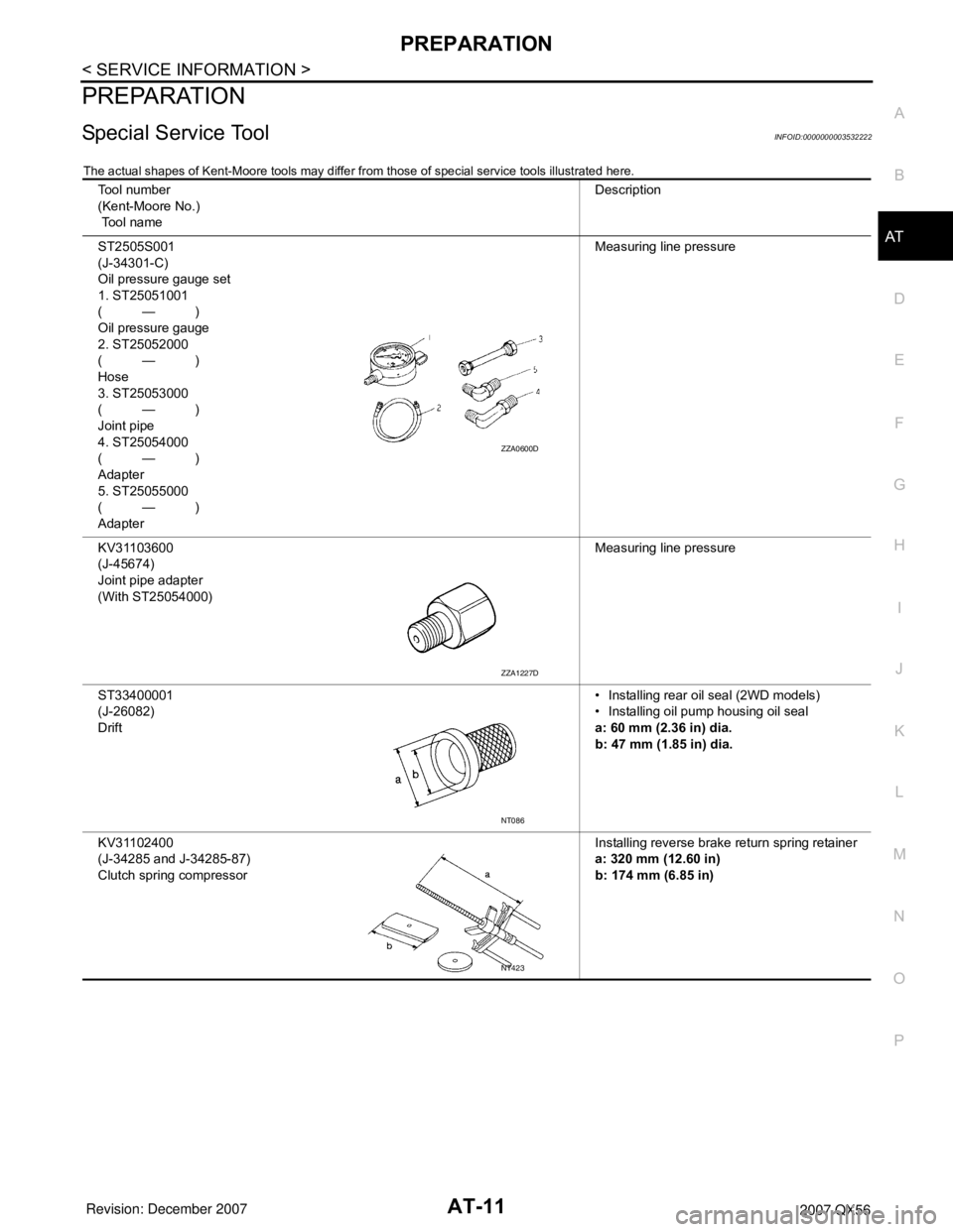
PREPARATION
Special Service ToolINFOID:0000000003532222
The actual shapes of Kent-Moore tools may differ from those of special service tools illustrated here.
Tool number
(Kent-Moore No.)
Tool nameDescription
ST2505S001
(J-34301-C)
Oil pressure gauge set
1. ST25051001
(—)
Oil pressure gauge
2. ST25052000
(—)
Hose
3. ST25053000
(—)
Joint pipe
4. ST25054000
(—)
Adapter
5. ST25055000
(—)
AdapterMeasuring line pressure
KV31103600
(J-45674)
Joint pipe adapter
(With ST25054000)Measuring line pressure
ST33400001
(J-26082)
Drift• Installing rear oil seal (2WD models)
• Installing oil pump housing oil seal
a: 60 mm (2.36 in) dia.
b: 47 mm (1.85 in) dia.
KV31102400
(J-34285 and J-34285-87)
Clutch spring compressorInstalling reverse brake return spring retainer
a: 320 mm (12.60 in)
b: 174 mm (6.85 in)
ZZA0600D
ZZA1227D
NT086
NT423
Page 84 of 3061
AT-14
< SERVICE INFORMATION >
A/T FLUID
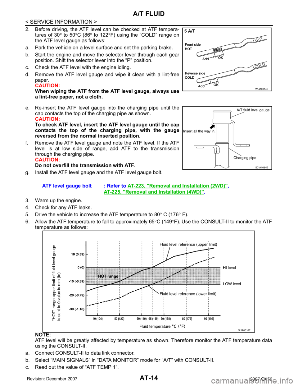
2. Before driving, the ATF level can be checked at ATF tempera-
tures of 30° to 50°C (86° to 122°F) using the “COLD” range on
the ATF level gauge as follows:
a. Park the vehicle on a level surface and set the parking brake.
b. Start the engine and move the selector lever through each gear
position. Shift the selector lever into the “P” position.
c. Check the ATF level with the engine idling.
d. Remove the ATF level gauge and wipe it clean with a lint-free
paper.
CAUTION:
When wiping the ATF from the ATF level gauge, always use
a lint-free paper, not a cloth.
e. Re-insert the ATF level gauge into the charging pipe until the
cap contacts the top of the charging pipe as shown.
CAUTION:
To check ATF level, insert the ATF level gauge until the cap
contacts the top of the charging pipe, with the gauge
reversed from the normal inserted position.
f. Remove the ATF level gauge and note the ATF level. If the ATF
level is at low side of range, add ATF to the transmission
through the charging pipe.
CAUTION:
Do not overfill the transmission with ATF.
g. Install the ATF level gauge and the ATF level gauge bolt.
3. Warm up the engine.
4. Check for any ATF leaks.
5. Drive the vehicle to increase the ATF temperature to 80° C (176° F).
6. Allow the ATF temperature to fall to approximately 65°C (149°F). Use the CONSULT-II to monitor the ATF
temperature as follows:
NOTE:
ATF level will be greatly affected by temperature as shown. Therefore monitor the ATF temperature data
using the CONSULT-II.
a. Connect CONSULT-II to data link connector.
b. Select “MAIN SIGNALS” in “DATA MONITOR” mode for “A/T” with CONSULT-II.
c. Read out the value of “ATF TEMP 1”.
WLIA0014E
ATF level gauge bolt : Refer to AT-223, "Removal and Installation (2WD)",
AT-225, "
Removal and Installation (4WD)".
SCIA1684E
SLIA0016E
Page 89 of 3061
A/T CONTROL SYSTEM
AT-19
< SERVICE INFORMATION >
D
E
F
G
H
I
J
K
L
MA
B
AT
N
O
P
A/T CONTROL SYSTEM
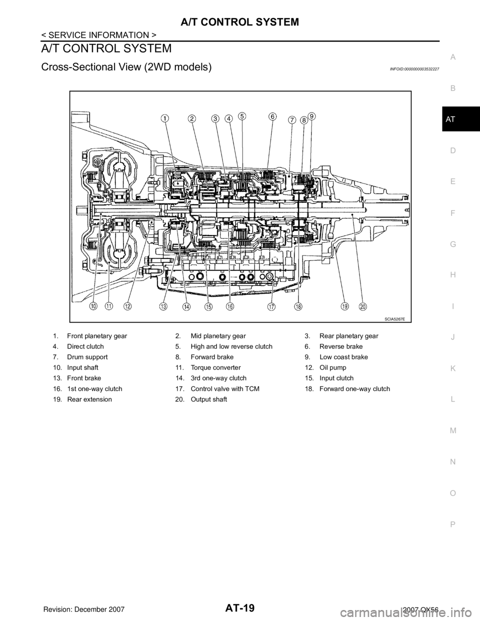
Cross-Sectional View (2WD models)INFOID:0000000003532227
1. Front planetary gear 2. Mid planetary gear 3. Rear planetary gear
4. Direct clutch 5. High and low reverse clutch 6. Reverse brake
7. Drum support 8. Forward brake 9. Low coast brake
10. Input shaft 11. Torque converter 12. Oil pump
13. Front brake 14. 3rd one-way clutch 15. Input clutch
16. 1st one-way clutch 17. Control valve with TCM 18. Forward one-way clutch
19. Rear extension 20. Output shaft
SCIA5267E
Page 90 of 3061
AT-20
< SERVICE INFORMATION >
A/T CONTROL SYSTEM
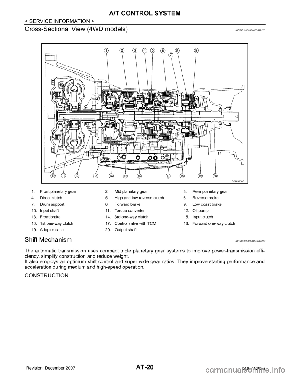
Cross-Sectional View (4WD models)
INFOID:0000000003532228
Shift MechanismINFOID:0000000003532229
The automatic transmission uses compact triple planetary gear systems to improve power-transmission effi-
ciency, simplify construction and reduce weight.
It also employs an optimum shift control and super wide gear ratios. They improve starting performance and
acceleration during medium and high-speed operation.
CONSTRUCTION
1. Front planetary gear 2. Mid planetary gear 3. Rear planetary gear
4. Direct clutch 5. High and low reverse clutch 6. Reverse brake
7. Drum support 8. Forward brake 9. Low coast brake
10. Input shaft 11. Torque converter 12. Oil pump
13. Front brake 14. 3rd one-way clutch 15. Input clutch
16. 1st one-way clutch 17. Control valve with TCM 18. Forward one-way clutch
19. Adapter case 20. Output shaft
SCIA5268E
Page 91 of 3061
A/T CONTROL SYSTEM
AT-21
< SERVICE INFORMATION >
D
E
F
G
H
I
J
K
L
MA
B
AT
N
O
P
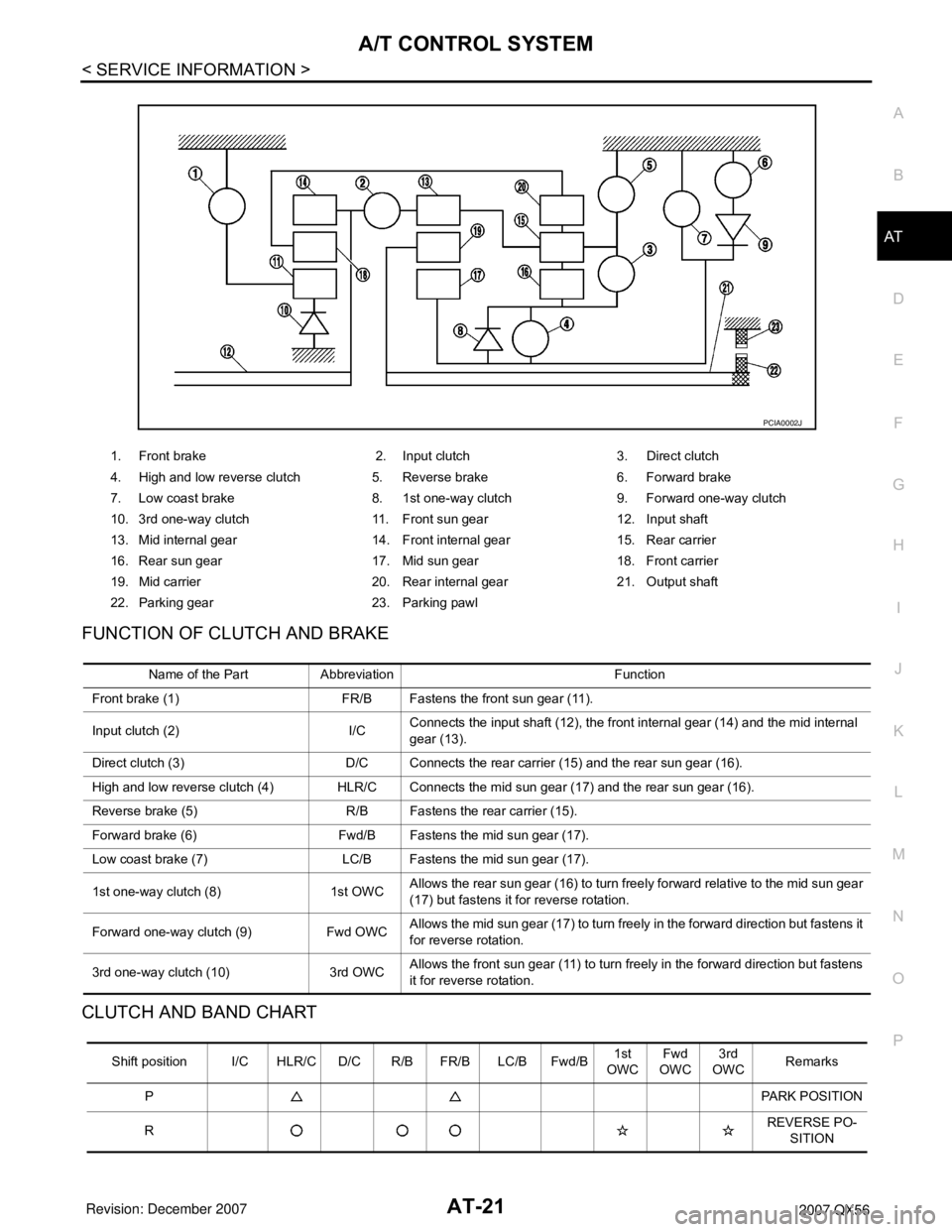
FUNCTION OF CLUTCH AND BRAKE
CLUTCH AND BAND CHART
1. Front brake 2. Input clutch 3. Direct clutch
4. High and low reverse clutch 5. Reverse brake 6. Forward brake
7. Low coast brake 8. 1st one-way clutch 9. Forward one-way clutch
10. 3rd one-way clutch 11. Front sun gear 12. Input shaft
13. Mid internal gear 14. Front internal gear 15. Rear carrier
16. Rear sun gear 17. Mid sun gear 18. Front carrier
19. Mid carrier 20. Rear internal gear 21. Output shaft
22. Parking gear 23. Parking pawl
PCIA0002J
Name of the Part Abbreviation Function
Front brake (1) FR/B Fastens the front sun gear (11).
Input clutch (2) I/CConnects the input shaft (12), the front internal gear (14) and the mid internal
gear (13).
Direct clutch (3) D/C Connects the rear carrier (15) and the rear sun gear (16).
High and low reverse clutch (4) HLR/C Connects the mid sun gear (17) and the rear sun gear (16).
Reverse brake (5) R/B Fastens the rear carrier (15).
Forward brake (6) Fwd/B Fastens the mid sun gear (17).
Low coast brake (7) LC/B Fastens the mid sun gear (17).
1st one-way clutch (8) 1st OWCAllows the rear sun gear (16) to turn freely forward relative to the mid sun gear
(17) but fastens it for reverse rotation.
Forward one-way clutch (9) Fwd OWCAllows the mid sun gear (17) to turn freely in the forward direction but fastens it
for reverse rotation.
3rd one-way clutch (10) 3rd OWCAllows the front sun gear (11) to turn freely in the forward direction but fastens
it for reverse rotation.
Shift position I/C HLR/C D/C R/B FR/B LC/B Fwd/B1st
OWCFwd
OWC3rd
OWCRemarks
PPARK POSITION
RREVERSE PO-
SITION
Page 93 of 3061

A/T CONTROL SYSTEM
AT-23
< SERVICE INFORMATION >
D
E
F
G
H
I
J
K
L
MA
B
AT
N
O
P
Since both the forward brake and the reverse brake are released, torque from the input shaft drive is not trans-
mitted to the output shaft.
“P” Position
• The same as for the “N” position, both the forward brake and the reverse brake are released, so torque from
the input shaft drive is not transmitted to the output shaft.
• The parking pawl linked with the select lever meshes with the parking gear and fastens the output shaft
mechanically.
“D”, “4”, “3”, “2” Positions 1st Gear
• The forward brake and the forward one-way clutch regulate reverse rotation of the mid sun gear.
• The 1st one-way clutch regulates reverse rotation of the rear sun gear.
• The 3rd one-way clutch regulates reverse rotation of the front sun gear.
• During deceleration, the mid sun gear turns forward, so the forward one-way clutch idles and the engine
brake is not activated.
1. Front brake 2. Input clutch 3. Direct clutch
4. High and low reverse clutch 5. Reverse brake 6. Forward brake
7. Low coast brake 8. 1st one-way clutch 9. Forward one-way clutch
10. 3rd one-way clutch 11. Front sun gear 12. Input shaft
13. Mid internal gear 14. Front internal gear 15. Rear carrier
16. Rear sun gear 17. Mid sun gear 18. Front carrier
19. Mid carrier 20. Rear internal gear 21. Output shaft
22. Parking gear 23. Parking pawl
PCIA0003J
Page 94 of 3061
AT-24
< SERVICE INFORMATION >
A/T CONTROL SYSTEM
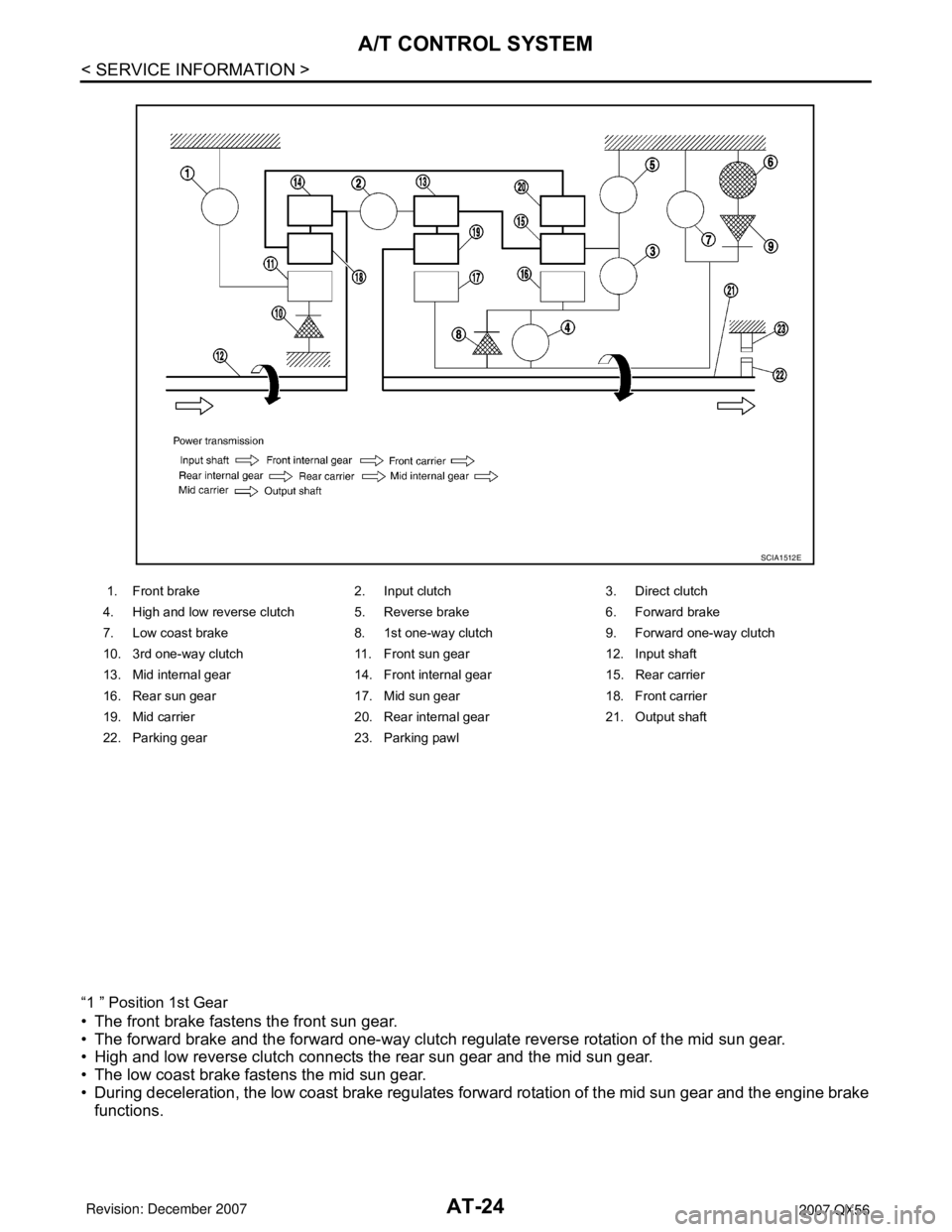
“1 ” Position 1st Gear
• The front brake fastens the front sun gear.
• The forward brake and the forward one-way clutch regulate reverse rotation of the mid sun gear.
• High and low reverse clutch connects the rear sun gear and the mid sun gear.
• The low coast brake fastens the mid sun gear.
• During deceleration, the low coast brake regulates forward rotation of the mid sun gear and the engine brake
functions.
1. Front brake 2. Input clutch 3. Direct clutch
4. High and low reverse clutch 5. Reverse brake 6. Forward brake
7. Low coast brake 8. 1st one-way clutch 9. Forward one-way clutch
10. 3rd one-way clutch 11. Front sun gear 12. Input shaft
13. Mid internal gear 14. Front internal gear 15. Rear carrier
16. Rear sun gear 17. Mid sun gear 18. Front carrier
19. Mid carrier 20. Rear internal gear 21. Output shaft
22. Parking gear 23. Parking pawl
SCIA1512E