ECU INFINITI QX56 2007 Factory Workshop Manual
[x] Cancel search | Manufacturer: INFINITI, Model Year: 2007, Model line: QX56, Model: INFINITI QX56 2007Pages: 3061, PDF Size: 64.56 MB
Page 289 of 3061
ON-VEHICLE SERVICE
AT-219
< SERVICE INFORMATION >
D
E
F
G
H
I
J
K
L
MA
B
AT
N
O
P
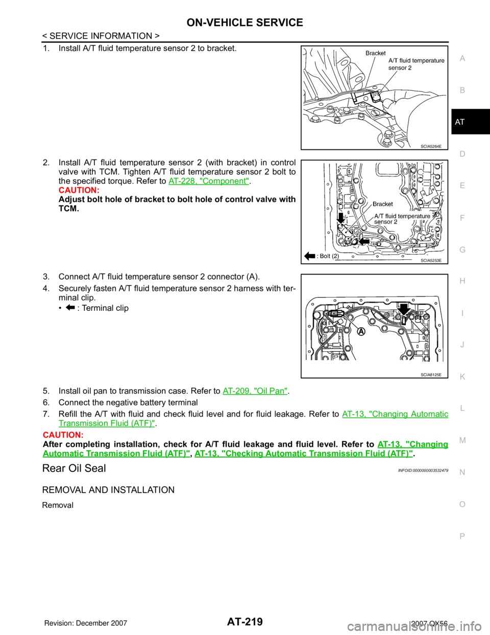
1. Install A/T fluid temperature sensor 2 to bracket.
2. Install A/T fluid temperature sensor 2 (with bracket) in control
valve with TCM. Tighten A/T fluid temperature sensor 2 bolt to
the specified torque. Refer to AT-228, "
Component".
CAUTION:
Adjust bolt hole of bracket to bolt hole of control valve with
TCM.
3. Connect A/T fluid temperature sensor 2 connector (A).
4. Securely fasten A/T fluid temperature sensor 2 harness with ter-
minal clip.
• : Terminal clip
5. Install oil pan to transmission case. Refer to AT-209, "
Oil Pan".
6. Connect the negative battery terminal
7. Refill the A/T with fluid and check fluid level and for fluid leakage. Refer to AT-13, "
Changing Automatic
Transmission Fluid (ATF)".
CAUTION:
After completing installation, check for A/T fluid leakage and fluid level. Refer to AT-13, "
Changing
Automatic Transmission Fluid (ATF)", AT-13, "Checking Automatic Transmission Fluid (ATF)".
Rear Oil SealINFOID:0000000003532479
REMOVAL AND INSTALLATION
Removal
SCIA5264E
SCIA5253E
SCIA8125E
Page 294 of 3061
AT-224
< SERVICE INFORMATION >
TRANSMISSION ASSEMBLY
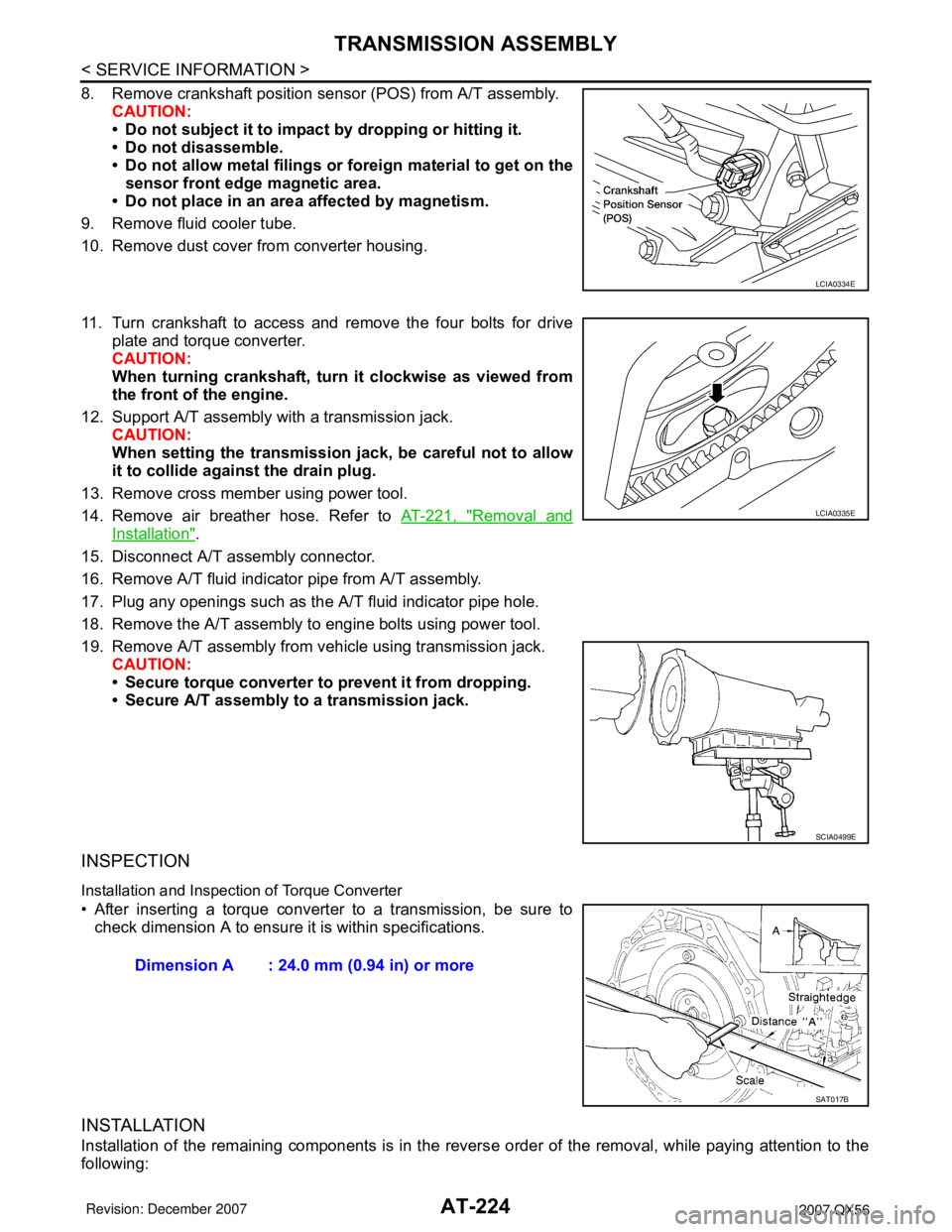
8. Remove crankshaft position sensor (POS) from A/T assembly.
CAUTION:
• Do not subject it to impact by dropping or hitting it.
• Do not disassemble.
• Do not allow metal filings or foreign material to get on the
sensor front edge magnetic area.
• Do not place in an area affected by magnetism.
9. Remove fluid cooler tube.
10. Remove dust cover from converter housing.
11. Turn crankshaft to access and remove the four bolts for drive
plate and torque converter.
CAUTION:
When turning crankshaft, turn it clockwise as viewed from
the front of the engine.
12. Support A/T assembly with a transmission jack.
CAUTION:
When setting the transmission jack, be careful not to allow
it to collide against the drain plug.
13. Remove cross member using power tool.
14. Remove air breather hose. Refer to AT-221, "
Removal and
Installation".
15. Disconnect A/T assembly connector.
16. Remove A/T fluid indicator pipe from A/T assembly.
17. Plug any openings such as the A/T fluid indicator pipe hole.
18. Remove the A/T assembly to engine bolts using power tool.
19. Remove A/T assembly from vehicle using transmission jack.
CAUTION:
• Secure torque converter to prevent it from dropping.
• Secure A/T assembly to a transmission jack.
INSPECTION
Installation and Inspection of Torque Converter
• After inserting a torque converter to a transmission, be sure to
check dimension A to ensure it is within specifications.
INSTALLATION
Installation of the remaining components is in the reverse order of the removal, while paying attention to the
following:
LCIA0334E
LCIA0335E
SCIA0499E
Dimension A : 24.0 mm (0.94 in) or more
SAT017B
Page 295 of 3061
TRANSMISSION ASSEMBLY
AT-225
< SERVICE INFORMATION >
D
E
F
G
H
I
J
K
L
MA
B
AT
N
O
P
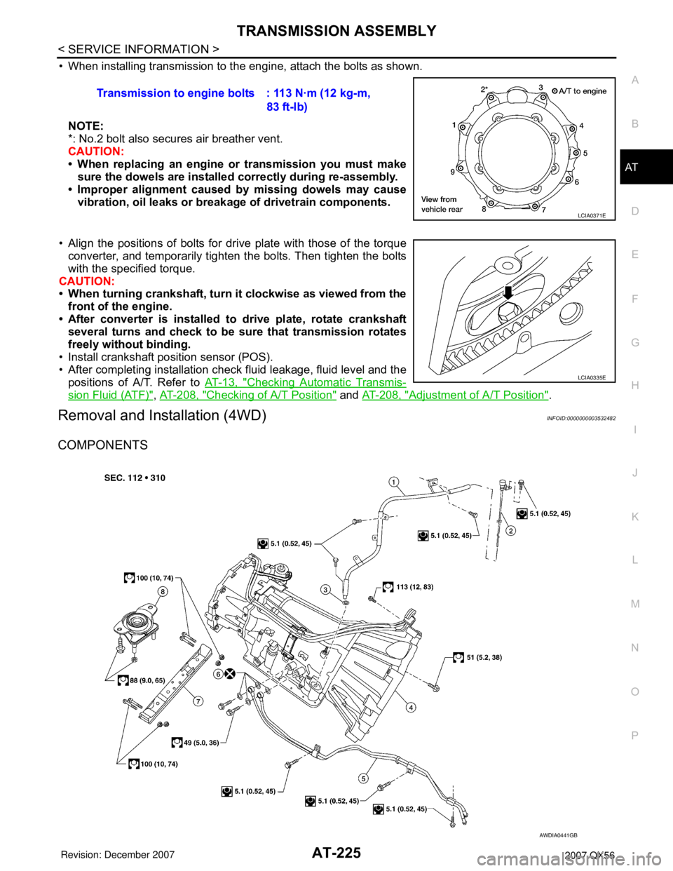
• When installing transmission to the engine, attach the bolts as shown.
NOTE:
*: No.2 bolt also secures air breather vent.
CAUTION:
• When replacing an engine or transmission you must make
sure the dowels are installed correctly during re-assembly.
• Improper alignment caused by missing dowels may cause
vibration, oil leaks or breakage of drivetrain components.
• Align the positions of bolts for drive plate with those of the torque
converter, and temporarily tighten the bolts. Then tighten the bolts
with the specified torque.
CAUTION:
• When turning crankshaft, turn it clockwise as viewed from the
front of the engine.
• After converter is installed to drive plate, rotate crankshaft
several turns and check to be sure that transmission rotates
freely without binding.
• Install crankshaft position sensor (POS).
• After completing installation check fluid leakage, fluid level and the
positions of A/T. Refer to AT-13, "
Checking Automatic Transmis-
sion Fluid (ATF)", AT-208, "Checking of A/T Position" and AT-208, "Adjustment of A/T Position".
Removal and Installation (4WD)INFOID:0000000003532482
COMPONENTS
Transmission to engine bolts : 113 N·m (12 kg-m,
83 ft-lb)
LCIA0371E
LCIA0335E
AWDIA0441GB
Page 297 of 3061
TRANSMISSION ASSEMBLY
AT-227
< SERVICE INFORMATION >
D
E
F
G
H
I
J
K
L
MA
B
AT
N
O
P
17. Plug any openings such as the fluid charging pipe hole.
18. Remove A/T assembly to engine bolts using power tool.
19. Remove A/T assembly with transfer from vehicle.
CAUTION:
• Secure torque converter to prevent it from dropping.
• Secure A/T assembly to transmission jack.
20. Remove transfer from A/T assembly. Refer to TF-128, "
Removal and Installation".
INSPECTION
Installation and Inspection of Torque Converter
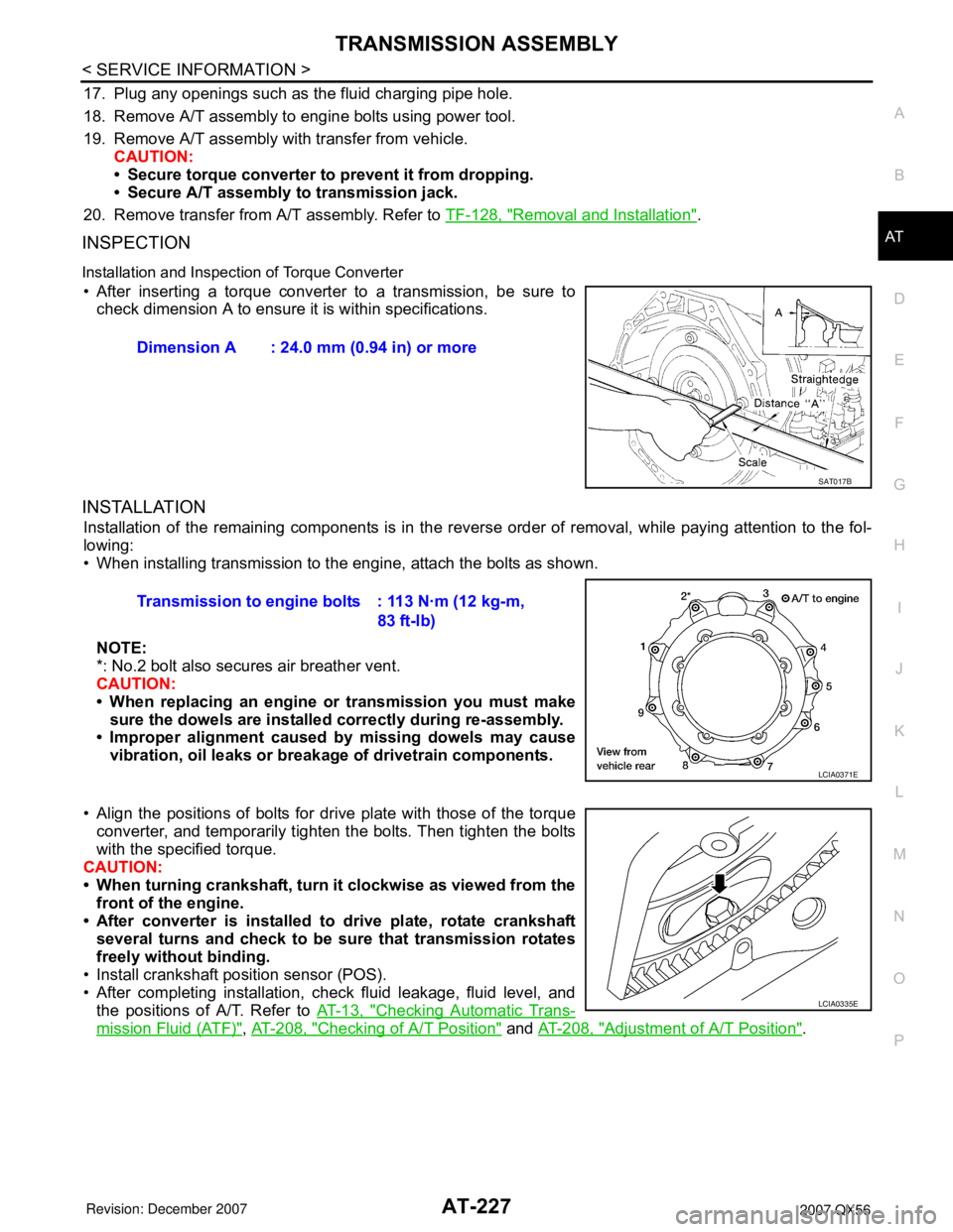
• After inserting a torque converter to a transmission, be sure to
check dimension A to ensure it is within specifications.
INSTALLATION
Installation of the remaining components is in the reverse order of removal, while paying attention to the fol-
lowing:
• When installing transmission to the engine, attach the bolts as shown.
NOTE:
*: No.2 bolt also secures air breather vent.
CAUTION:
• When replacing an engine or transmission you must make
sure the dowels are installed correctly during re-assembly.
• Improper alignment caused by missing dowels may cause
vibration, oil leaks or breakage of drivetrain components.
• Align the positions of bolts for drive plate with those of the torque
converter, and temporarily tighten the bolts. Then tighten the bolts
with the specified torque.
CAUTION:
• When turning crankshaft, turn it clockwise as viewed from the
front of the engine.
• After converter is installed to drive plate, rotate crankshaft
several turns and check to be sure that transmission rotates
freely without binding.
• Install crankshaft position sensor (POS).
• After completing installation, check fluid leakage, fluid level, and
the positions of A/T. Refer to AT-13, "
Checking Automatic Trans-
mission Fluid (ATF)", AT-208, "Checking of A/T Position" and AT-208, "Adjustment of A/T Position". Dimension A : 24.0 mm (0.94 in) or more
SAT017B
Transmission to engine bolts : 113 N·m (12 kg-m,
83 ft-lb)
LCIA0371E
LCIA0335E
Page 313 of 3061
DISASSEMBLY
AT-243
< SERVICE INFORMATION >
D
E
F
G
H
I
J
K
L
MA
B
AT
N
O
P
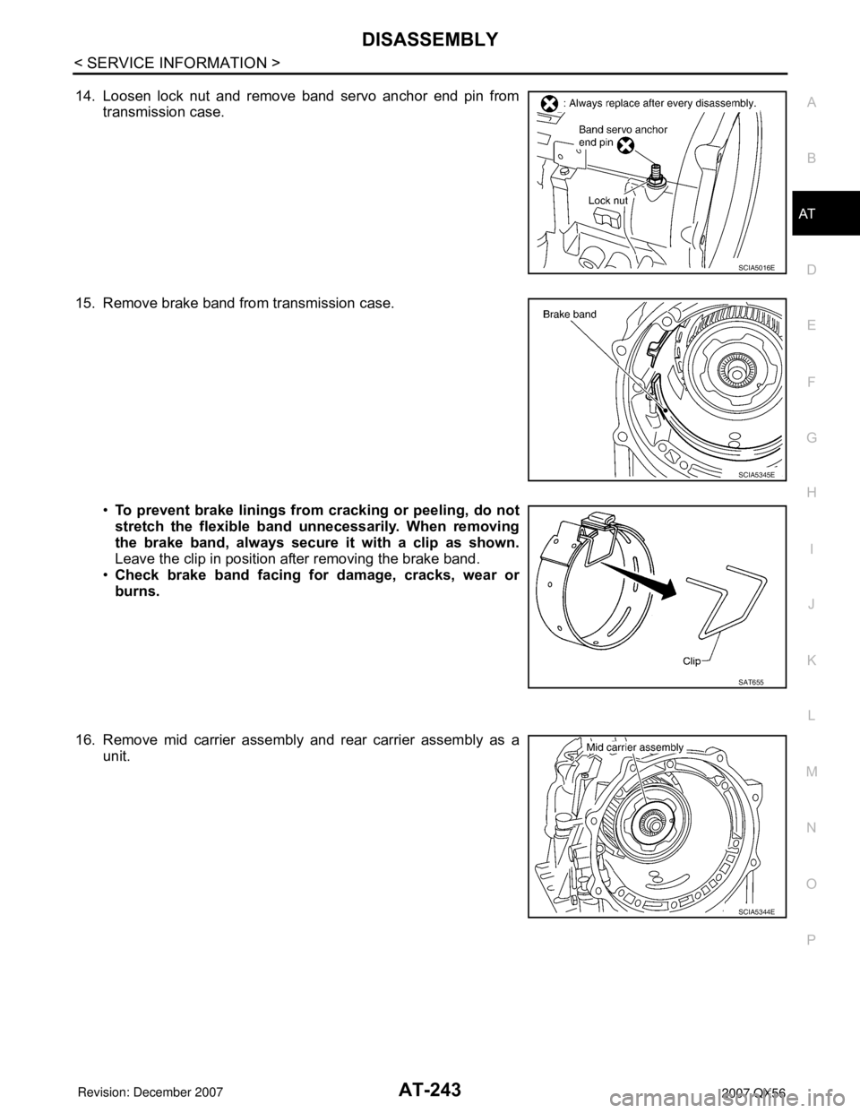
14. Loosen lock nut and remove band servo anchor end pin from
transmission case.
15. Remove brake band from transmission case.
•To prevent brake linings from cracking or peeling, do not
stretch the flexible band unnecessarily. When removing
the brake band, always secure it with a clip as shown.
Leave the clip in position after removing the brake band.
•Check brake band facing for damage, cracks, wear or
burns.
16. Remove mid carrier assembly and rear carrier assembly as a
unit.
SCIA5016E
SCIA5345E
SAT655
SCIA5344E
Page 350 of 3061
AT-280
< SERVICE INFORMATION >
ASSEMBLY
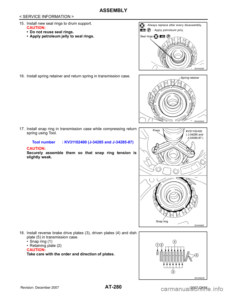
15. Install new seal rings to drum support.
CAUTION:
• Do not reuse seal rings.
• Apply petroleum jelly to seal rings.
16. Install spring retainer and return spring in transmission case.
17. Install snap ring in transmission case while compressing return
spring using Tool.
CAUTION:
Securely assemble them so that snap ring tension is
slightly weak.
18. Install reverse brake drive plates (3), driven plates (4) and dish
plate (5) in transmission case.
• Snap ring (1)
• Retaining plate (2)
CAUTION:
Take care with the order and direction of plates.
SCIA3333E
SCIA2324E
Tool number : KV31102400 (J-34285 and J-34285-87)
SCIA5582E
WCIA0625E
Page 365 of 3061
ASSEMBLY
AT-295
< SERVICE INFORMATION >
D
E
F
G
H
I
J
K
L
MA
B
AT
N
O
P
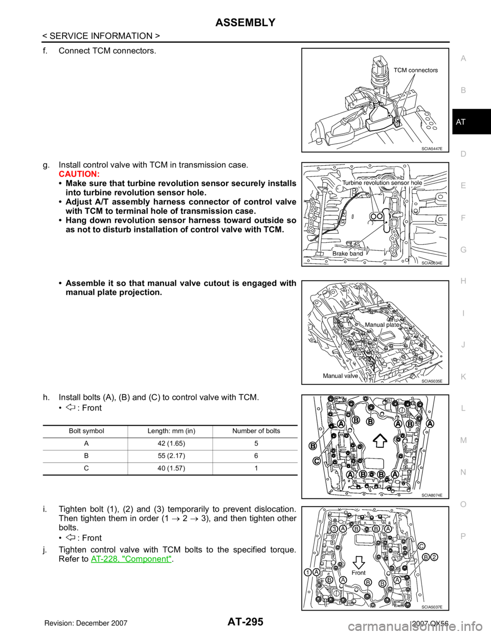
f. Connect TCM connectors.
g. Install control valve with TCM in transmission case.
CAUTION:
• Make sure that turbine revolution sensor securely installs
into turbine revolution sensor hole.
• Adjust A/T assembly harness connector of control valve
with TCM to terminal hole of transmission case.
• Hang down revolution sensor harness toward outside so
as not to disturb installation of control valve with TCM.
• Assemble it so that manual valve cutout is engaged with
manual plate projection.
h. Install bolts (A), (B) and (C) to control valve with TCM.
• : Front
i. Tighten bolt (1), (2) and (3) temporarily to prevent dislocation.
Then tighten them in order (1 → 2 → 3), and then tighten other
bolts.
• : Front
j. Tighten control valve with TCM bolts to the specified torque.
Refer to AT-228, "
Component".
SCIA5447E
SCIA5034E
SCIA5035E
Bolt symbol Length: mm (in) Number of bolts
A 42 (1.65) 5
B 55 (2.17) 6
C 40 (1.57) 1
SCIA8074E
SCIA5037E
Page 366 of 3061
AT-296
< SERVICE INFORMATION >
ASSEMBLY
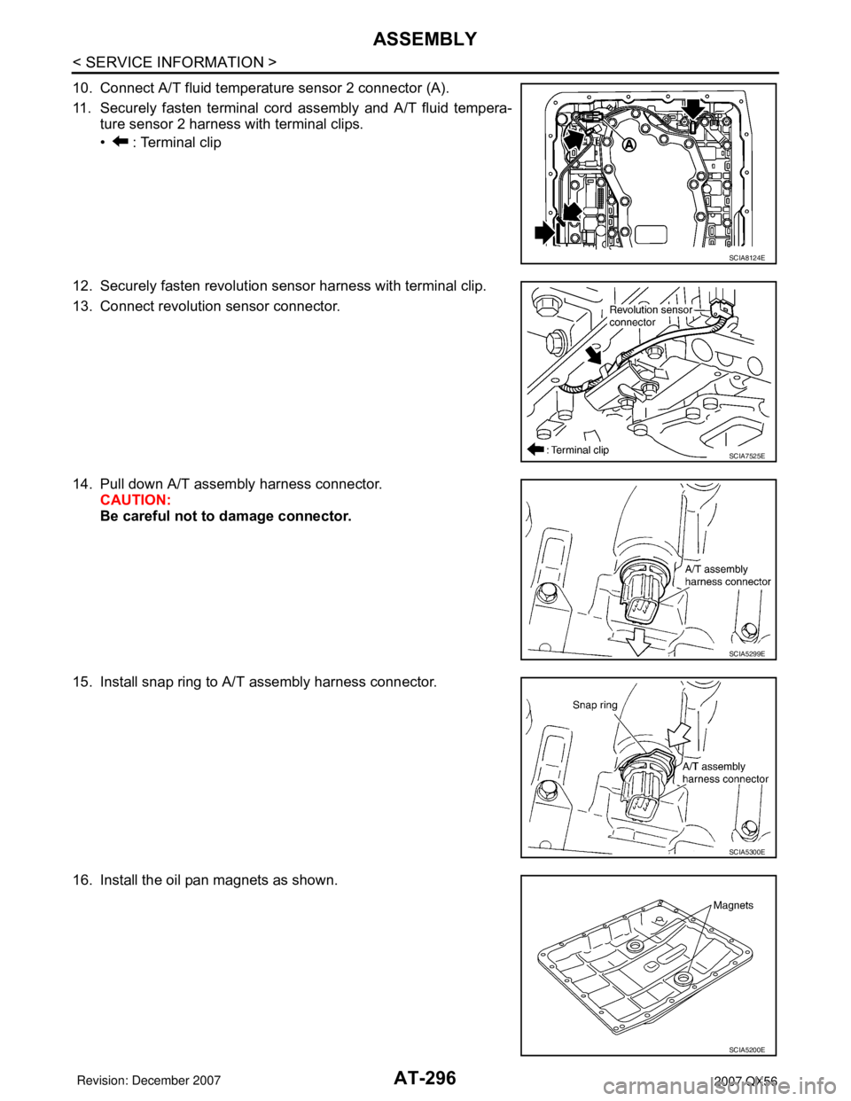
10. Connect A/T fluid temperature sensor 2 connector (A).
11. Securely fasten terminal cord assembly and A/T fluid tempera-
ture sensor 2 harness with terminal clips.
• : Terminal clip
12. Securely fasten revolution sensor harness with terminal clip.
13. Connect revolution sensor connector.
14. Pull down A/T assembly harness connector.
CAUTION:
Be careful not to damage connector.
15. Install snap ring to A/T assembly harness connector.
16. Install the oil pan magnets as shown.
SCIA8124E
SCIA7525E
SCIA5299E
SCIA5300E
SCIA5200E
Page 400 of 3061
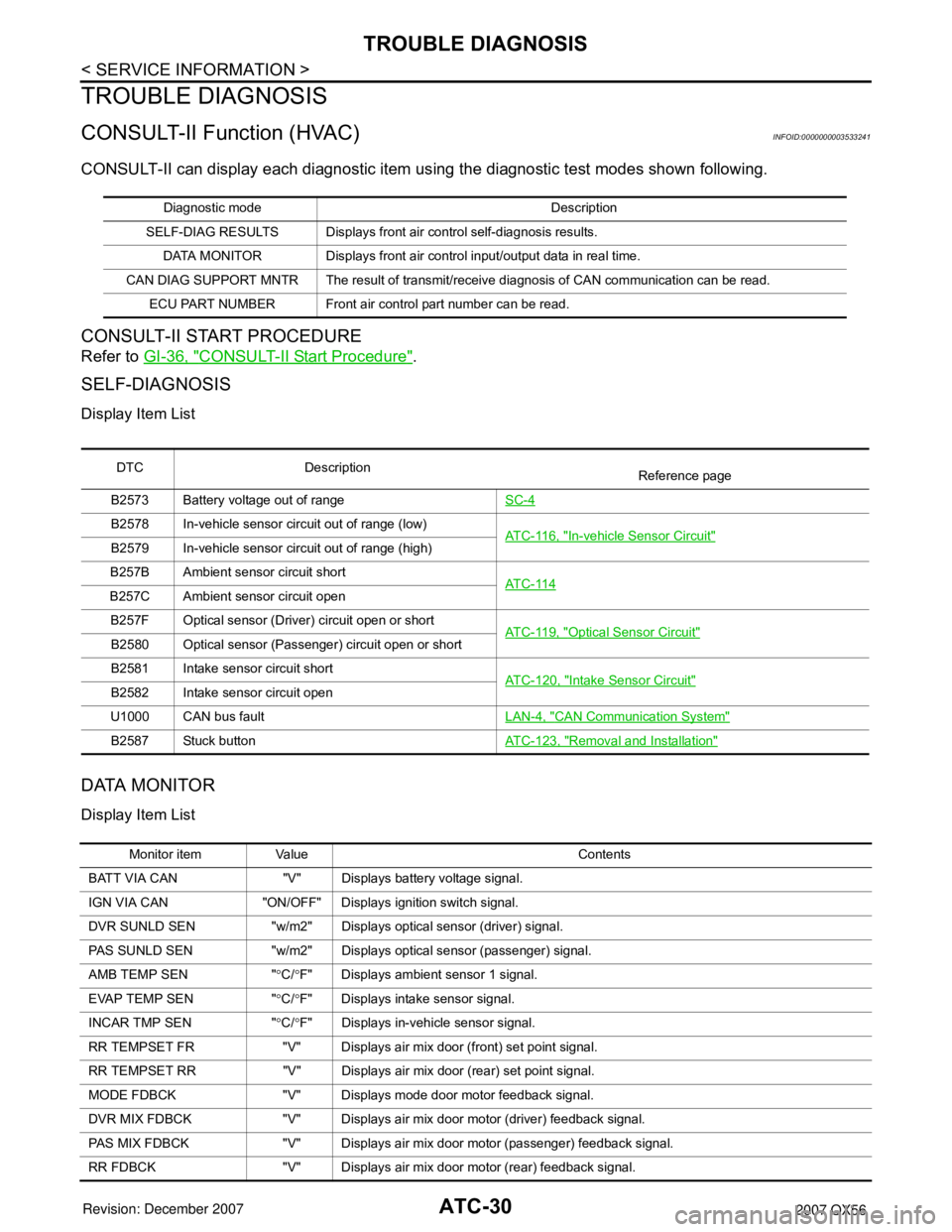
ATC-30
< SERVICE INFORMATION >
TROUBLE DIAGNOSIS
TROUBLE DIAGNOSIS
CONSULT-II Function (HVAC)INFOID:0000000003533241
CONSULT-II can display each diagnostic item using the diagnostic test modes shown following.
CONSULT-II START PROCEDURE
Refer to GI-36, "CONSULT-II Start Procedure".
SELF-DIAGNOSIS
Display Item List
DATA MONITOR
Display Item List
Diagnostic mode Description
SELF-DIAG RESULTS Displays front ai r control self-diagnosis results.
DATA MONITOR Displays front air control input/output data in real time.
CAN DIAG SUPPORT MNTR The result of transmit/receive diagnosis of CAN communication can be read. ECU PART NUMBER Front air control part number can be read.
DTC Description Reference page
B2573 Battery voltage out of range SC-4
B2578 In-vehicle sensor circuit out of range (low)
AT C - 11 6 , "In-vehicle Sensor Circuit"B2579 In-vehicle sensor circuit out of range (high)
B257B Ambient sensor circuit short AT C - 11 4
B257C Ambient sensor circuit open
B257F Optical sensor (Driver) circuit open or short AT C - 11 9 , "
Optical Sensor Circuit"B2580 Optical sensor (Passenger) circuit open or short
B2581 Intake sensor circuit shortATC-120, "
Intake Sensor Circuit"B2582 Intake sensor circuit open
U1000 CAN bus fault LAN-4, "
CAN Communication System"
B2587 Stuck buttonATC-123, "Removal and Installation"
Monitor item Value Contents
BATT VIA CAN "V" Displays battery voltage signal.
IGN VIA CAN "ON/OFF" Displays ignition switch signal.
DVR SUNLD SEN "w/m2" Displays optical sensor (driver) signal.
PAS SUNLD SEN "w/m2" Displays optical sensor (passenger) signal.
AMB TEMP SEN " °C/ °F" Displays ambient sensor 1 signal.
EVAP TEMP SEN " °C/ °F" Displays intake sensor signal.
INCAR TMP SEN " °C/ °F" Displays in-vehicle sensor signal.
RR TEMPSET FR "V" Displays air mix door (front) set point signal.
RR TEMPSET RR "V" Displays air mi x door (rear) set point signal.
MODE FDBCK "V" Displays mode door motor feedback signal.
DVR MIX FDBCK "V" Displays air mix do or motor (driver) feedback signal.
PAS MIX FDBCK "V" Displays air mix door motor (passenger) feedback signal.
RR FDBCK "V" Displays air mix door motor (rear) feedback signal.
Page 401 of 3061
TROUBLE DIAGNOSISATC-31
< SERVICE INFORMATION >
C
DE
F
G H
I
K L
M A
B
AT C
N
O P
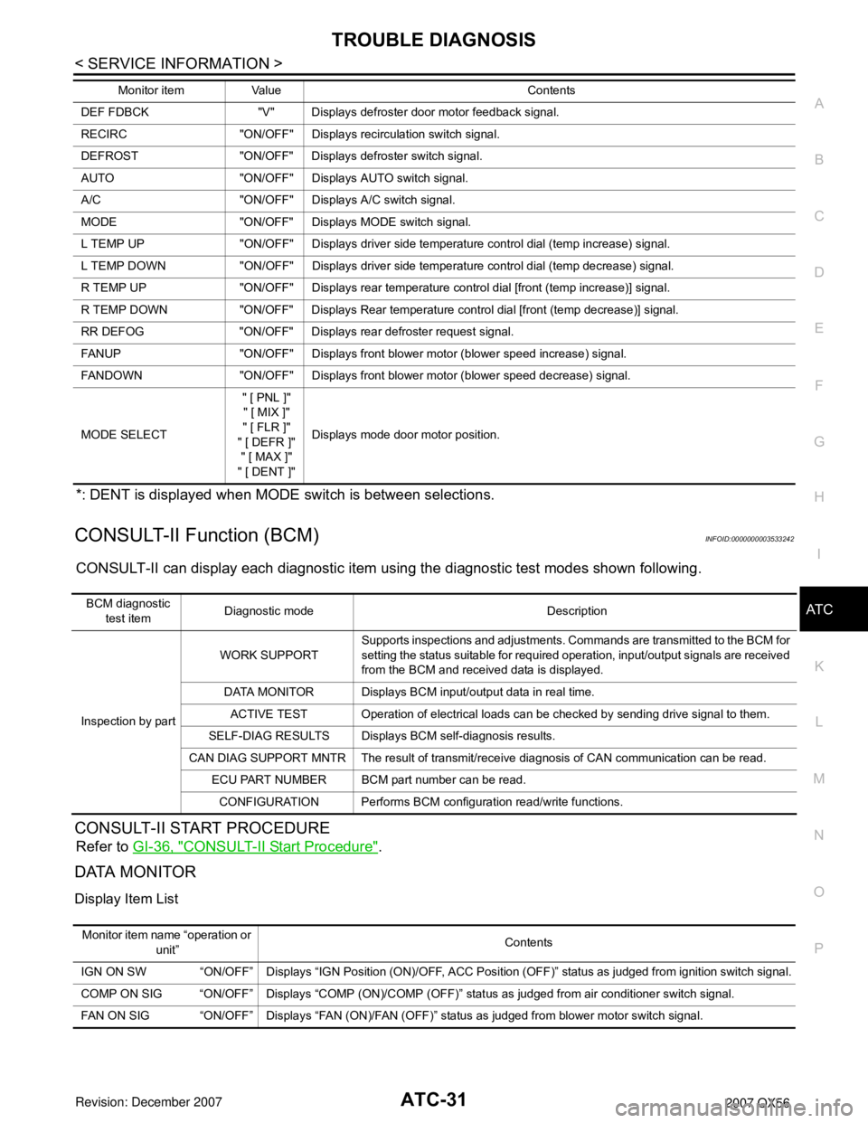
*: DENT is displayed when MODE switch is between selections.
CONSULT-II Function (BCM)INFOID:0000000003533242
CONSULT-II can display each diagnostic item us ing the diagnostic test modes shown following.
CONSULT-II START PROCEDURE
Refer to GI-36, "CONSULT-II Start Procedure".
DATA MONITOR
Display Item List
DEF FDBCK "V" Displays defroster door motor feedback signal.
RECIRC "ON/OFF" Disp lays recirculation switch signal.
DEFROST "ON/OFF" Displays defroster switch signal.
AUTO "ON/OFF" Displays AUTO switch signal.
A/C "ON/OFF" Displays A/C switch signal.
MODE "ON/OFF" Displays MODE switch signal.
L TEMP UP "ON/OFF" Displays driver side temperature control dial (temp increase) signal.
L TEMP DOWN "ON/OFF" Displays driver side temperature control dial (temp decrease) signal.
R TEMP UP "ON/OFF" Displays rear temperature control dial [front (temp increase)] signal.
R TEMP DOWN "ON/OFF" Displays Rear temperature control dial [front (temp decrease)] signal.
RR DEFOG "ON/OFF" Displays rear defroster request signal.
FANUP "ON/OFF" Displays front blower motor (blower speed increase) signal.
FANDOWN "ON/OFF" Displays front blower motor (blower speed decrease) signal.
MODE SELECT " [ PNL ]"
" [ MIX ]"
" [ FLR ]"
" [ DEFR ]" " [ MAX ]"
" [ DENT ]" Displays mode door motor position.
Monitor item Value Contents
BCM diagnostic
test item Diagnostic mode Description
Inspection by part WORK SUPPORT
Supports inspections and adjustments. Commands are transmitted to the BCM for
setting the status suitable for required operation, input/output signals are received
from the BCM and received data is displayed.
DATA MONITOR Displays BCM input/output data in real time. ACTIVE TEST Operation of electrical loads can be checked by sending drive signal to them.
SELF-DIAG RESULTS Displays BCM self-diagnosis results.
CAN DIAG SUPPORT MNTR The result of transmit/receive diagnosis of CAN communication can be read. ECU PART NUMBER BCM part number can be read.
CONFIGURATION Performs BCM configuration read/write functions.
Monitor item name “operation or unit” Contents
IGN ON SW “ON/OFF” Displays “IGN Position (ON)/OFF, ACC Position (OFF)” status as judged from ignition switch signal.
COMP ON SIG “ON/OFF” Displays “COMP (ON)/COMP (OFF)” stat us as judged from air conditioner switch signal.
FAN ON SIG “ON/OFF” Displays “FAN (ON)/FAN (OFF)” status as judged from blower motor switch signal.