rear door INFINITI QX56 2007 Factory Service Manual
[x] Cancel search | Manufacturer: INFINITI, Model Year: 2007, Model line: QX56, Model: INFINITI QX56 2007Pages: 3061, PDF Size: 64.56 MB
Page 371 of 3061

ATC-1
AIR CONDITIONER
C
DE
F
G H
I
K L
M
SECTION AT C
A
B
AT C
N
O P
CONTENTS
AUTOMATIC AIR CONDITIONER
SERVICE INFORMATION .. ..........................3
PRECAUTIONS .............................................. .....3
Precaution for Supplemental Restraint System
(SRS) "AIR BAG" and "SEAT BELT PRE-TEN-
SIONER" ............................................................. ......
3
Precaution for Working with HFC-134a (R-134a) ......3
Contaminated Refrigerant .........................................3
General Refrigerant Precaution ................................4
Precaution for Leak Detection Dye ...........................4
A/C Identification Label .............................................4
Precaution for Refrigerant Connection ......................4
Precaution for Service of Compressor ................ ......9
Precaution for Service Equipment ....................... ......9
PREPARATION ..................................................12
Special Service Tool ........................................... ....12
HFC-134a (R-134a) Service Tool and Equipment ....12
Commercial Service Tool ........................................14
REFRIGERATION SYSTEM ..............................16
Refrigerant Cycle ................................................ ....16
Refrigerant System Protection ................................16
Component Part Location ................................... ....17
OIL ......................................................................20
Maintenance of Oil Quantity in Compressor ....... ....20
AIR CONDITIONER CONTROL .........................22
Description .......................................................... ....22
Operation ................................................................22
Description of Control System .................................23
Control Operation ....................................................24
Discharge Air Flow ..................................................26
System Description (Front) .....................................27
System Description (Rear) .................................. ....28
CAN Communication System Description ...............29
TROUBLE DIAGNOSIS .....................................30
CONSULT-II Function (HVAC) ............................ ....30
CONSULT-II Function (BCM) ..................................31
How to Perform Trouble Diagnosis for Quick and
Accurate Repair ................................................... ....
32
Component Parts and Harness Connector Loca-
tion ...........................................................................
32
Schematic ................................................................36
Wiring Diagram - A/C,A - .........................................37
Front Air Control Terminal and Reference Value ....47
A/C System Self-Diagnosis Function .......................48
Operational Check (Front) ................................... ....50
Operational Check (Rear) ........................................51
Power Supply and Ground Circuit for Front Air
Control ................................................................. ....
52
Mode Door Motor Circuit .........................................54
Air Mix Door Motor Circuit ................................... ....59
Intake Door Motor Circuit .........................................70
Defroster Door Motor Circuit ....................................74
Front Blower Motor Circuit .......................................78
Rear Blower Motor Circuit ................................... ....85
Rear Air Control Circuit ............................................93
Magnet Clutch Circuit ..............................................96
Insufficient Cooling ................................................100
Insufficient Heating ................................................108
Noise .....................................................................109
Self-Diagnosis .......................................................111
Memory Function ...................................................112
Water Valve Circuit ................................................113
Ambient Sensor Circuit ..........................................114
In-vehicle Sensor Circuit ........................................116
Optical Sensor Circuit ............................................119
Intake Sensor Circuit .............................................120
CONTROL UNIT ..............................................123
Removal and Installation .......................................123
AMBIENT SENSOR ........................................124
Removal and Installation .......................................124
IN-VEHICLE SENSOR ....................................125
Removal and Installation .......................................125
OPTICAL SENSOR .........................................126
Page 372 of 3061

ATC-2
Removal and Installation .......................................126
INTAKE SENSOR ............................................127
Removal and Installation ..................................... ..127
BLOWER MOTOR ...........................................128
Component .......................................................... ..128
Removal and Installation .......................................128
IN-CABIN MICROFILTER ................................130
Removal and Installation ..................................... ..130
HEATER & COOLING UNIT ASSEMBLY .......132
Component .......................................................... ..132
Removal and Installation .......................................133
HEATER CORE ...............................................135
Component .......................................................... ..135
Removal and Installation .......................................136
DEFROSTER DOOR MOTOR .........................138
Removal and Installation ..................................... ..138
INTAKE DOOR MOTOR ..................................139
Removal and Installation ..................................... ..139
MODE DOOR MOTOR ....................................140
Removal and Installation ..................................... ..140
AIR MIX DOOR MOTOR ..................................141
Component .......................................................... ..141
Removal and Installation .......................................141
VARIABLE BLOWER CONTROL ...................143
Removal and Installation ..................................... ..143
REAR BLOWER MOTOR RESISTOR ............144
Removal and Installation ..................................... ..144
DUCTS AND GRILLES ....................................145
Component .......................................................... .145
Removal and Installation .......................................148
REFRIGERANT LINES ................................... ..150
HFC-134a (R-134a) Service Procedure ............... .150
Component ...........................................................152
Removal and Installation for Compressor .............154
Removal and Installation for Compressor Clutch ..155
Removal and Installation for Low-Pressure Flexi-
ble Hose ............................................................... .
158
Removal and Installation for High-pressure Flexi-
ble Hose ............................................................... .
158
Removal and Installation for High-pressure Pipe ..158
Removal and Installation for Low-Pressure Pipe ..159
Removal and Installation for Rear High- and Low-
Pressure A/C and Heater Core Pipes .................. .
159
Removal and Installation for Underfloor Rear
High- and Low-Pressure A/C and Heater Core
Pipes .................................................................... .
160
Removal and Installation for Refrigerant Pressure
Sensor .................................................................. .
161
Removal and Installation for Condenser ...............161
Removal and Installation for Front Evaporator .....163
Removal and Installation for Rear Evaporator ......164
Removal and Installation for Front Expansion
Valve .....................................................................
165
Removal and Installation for Rear Expansion
Valve .................................................................... .
165
Checking of Refrigerant Leaks ..............................166
Checking System for Leaks Using the Fluorescent
Dye Leak Detector ................................................
166
Dye Injection .........................................................166
Electronic Refrigerant Leak Detector ....................167
SERVICE DATA AND SPECIFICATIONS
(SDS) ................................................................
170
Service Data and Specification (SDS) ..................170
Page 392 of 3061

ATC-22
< SERVICE INFORMATION >
AIR CONDITIONER CONTROL
AIR CONDITIONER CONTROL
DescriptionINFOID:0000000003533233
The front air control provides automatic regulation of the vehicle's interior temperature. The system is based
on the driver's and passenger's selected "set temperat ure", regardless of the outside temperature changes.
This is done by utilizing a microcomputer, also referred to as the front air control, which receives input signals
from the following seven sensors:
• Ambient sensor
• In-vehicle sensor
• Intake sensor
• Optical sensor (providing one input for driver and one input for passenger side)
• PBR (Position Balanced Resistor)
• Vehicle speed sensor (via CAN communication)
• Engine coolant temperature (via CAN communication)
The front air control uses these signals (including the set temperature) to automatically control:
• Outlet air volume
• Air temperature
• Air distribution
The front air control also provides separate regulation of the vehicle's interior temperature for the rear passen-
ger area. The system is based on the temperature and r ear blower settings selected from rear control
switches located on the front air control, or from the temperature and rear blower settings selected from rear
control switches on the rear air control, when the front air control switches are set to the rear position.
The front air control is used to select: • Outlet air volume
• Air temperature/distribution
OperationINFOID:0000000003533234
AIR MIX DOORS CONTROL
The air mix doors are automatically controlled so that in-vehicle temperature is maintained at a predetermined
value by the temperature setting, ambient temper ature, in-vehicle temperature and amount of sunload.
BLOWER SPEED CONTROL
Blower speed is automatically controlled by the temperat ure setting, ambient temperature, in-vehicle tempera-
ture, intake temperature, amount of sunload and air mix door position.
When AUTO switch is pressed, the blower motor starts to gradually increase air flow volume (if required).
When engine coolant temperature is low, the blower moto r operation is delayed to prevent cool air from flow-
ing.
INTAKE DOOR CONTROL
The intake door is automatically controlled by the tem perature setting, ambient temperature, in-vehicle tem-
perature, intake temperature, amount of sunl oad and by the ON-OFF operation of the compressor.
MODE DOOR CONTROL
The mode door is automatically controlled by the temperat ure setting, ambient temperature, in-vehicle temper-
ature, intake temperature and amount of sunload.
DEFROSTER DOOR CONTROL
The defroster door is controlled by: Turning the defroster dial to front defroster.
Page 395 of 3061
AIR CONDITIONER CONTROLATC-25
< SERVICE INFORMATION >
C
DE
F
G H
I
K L
M A
B
AT C
N
O P
TEMPERATURE CONTROL DIAL (TEMPE RATURE CONTROL) (DRIVER SIDE)
Increases or decreases the set temperature.
TEMPERATURE CONTROL DIAL (TEMPERATURE CONTROL) (PASSENGER SIDE)
Increases or decreases the set temperature.
TEMPERATURE CONTROL DIAL (TEMPERA TURE AND MODE CONTROL) (REAR)
Increases or decreases the set temperature. The mode al so changes from foot at full hot setting, to foot/vent
mid-range (warm) setting, and then to panel on full cold setting.
RECIRCULATION ( ) SWITCH
• When REC switch is ON, REC switch indicator turns ON, and air inlet is set to REC.
• When REC switch is turned OFF, or when compressor is turned from ON to OFF, REC switch is automati-
cally turned OFF. REC mode can be re-entered by pressing REC switch again.
• REC switch is not operated when DEF switch is tu rned ON, at the D/F position or in floor position.
DEFROSTER ( ) SWITCH
Positions the air outlet doors to the defrost position. Al so positions the intake doors to the outside air position.
REAR WINDOW DEFOGGER SWITCH
When switch is ON, rear window and door mirrors are defogged.
OFF SWITCH
The compressor and blower are OFF, the intake doors are set to the outside air position, and the air outlet
doors are set to the foot (75% foot and 25% defrost) position.
A/C SWITCH
The compressor is ON or OFF.
(Pressing the A/C switch when the AUTO switch is ON will turn off the A/C switch and compressor.)
MODE SWITCH (FRONT)
Controls the air discharge outlets.
FRONT BLOWER CONTROL DIAL
Manually control the blower speed. Seven speeds are av ailable for manual control (as shown on the display
screen).
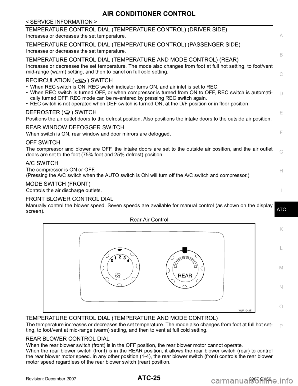
Rear Air Control
TEMPERATURE CONTROL DIAL (TEM PERATURE AND MODE CONTROL)
The temperature increases or decreases the set temperat ure. The mode also changes from foot at full hot set-
ting, to foot/vent at mid-range (warm) setti ng, and then to vent at full cold setting.
REAR BLOWER CONTROL DIAL
When the rear blower switch (front) is in the OFF position, the rear blower motor cannot operate.
When the rear blower switch (front) is in the REAR positi on, it allows the rear blower switch (rear) to control
the rear blower motor speed. In any other position (1-4), the rear blower switch (front) controls the rear blower
motor speed regardless of the rear blower switch (rear) position.
WJIA1042E
Page 400 of 3061
ATC-30
< SERVICE INFORMATION >
TROUBLE DIAGNOSIS
TROUBLE DIAGNOSIS
CONSULT-II Function (HVAC)INFOID:0000000003533241
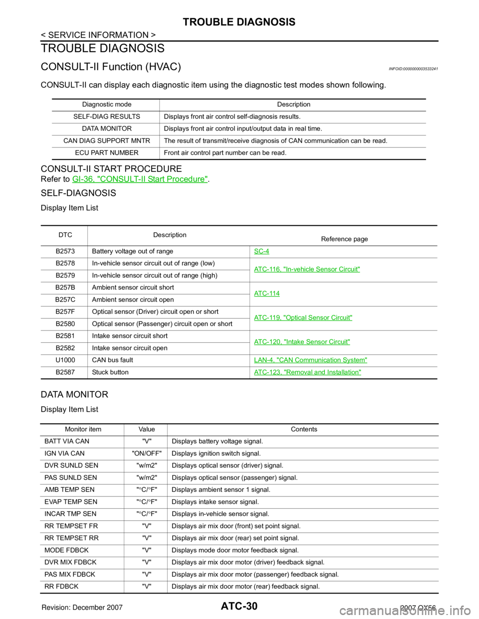
CONSULT-II can display each diagnostic item using the diagnostic test modes shown following.
CONSULT-II START PROCEDURE
Refer to GI-36, "CONSULT-II Start Procedure".
SELF-DIAGNOSIS
Display Item List
DATA MONITOR
Display Item List
Diagnostic mode Description
SELF-DIAG RESULTS Displays front ai r control self-diagnosis results.
DATA MONITOR Displays front air control input/output data in real time.
CAN DIAG SUPPORT MNTR The result of transmit/receive diagnosis of CAN communication can be read. ECU PART NUMBER Front air control part number can be read.
DTC Description Reference page
B2573 Battery voltage out of range SC-4
B2578 In-vehicle sensor circuit out of range (low)
AT C - 11 6 , "In-vehicle Sensor Circuit"B2579 In-vehicle sensor circuit out of range (high)
B257B Ambient sensor circuit short AT C - 11 4
B257C Ambient sensor circuit open
B257F Optical sensor (Driver) circuit open or short AT C - 11 9 , "
Optical Sensor Circuit"B2580 Optical sensor (Passenger) circuit open or short
B2581 Intake sensor circuit shortATC-120, "
Intake Sensor Circuit"B2582 Intake sensor circuit open
U1000 CAN bus fault LAN-4, "
CAN Communication System"
B2587 Stuck buttonATC-123, "Removal and Installation"
Monitor item Value Contents
BATT VIA CAN "V" Displays battery voltage signal.
IGN VIA CAN "ON/OFF" Displays ignition switch signal.
DVR SUNLD SEN "w/m2" Displays optical sensor (driver) signal.
PAS SUNLD SEN "w/m2" Displays optical sensor (passenger) signal.
AMB TEMP SEN " °C/ °F" Displays ambient sensor 1 signal.
EVAP TEMP SEN " °C/ °F" Displays intake sensor signal.
INCAR TMP SEN " °C/ °F" Displays in-vehicle sensor signal.
RR TEMPSET FR "V" Displays air mix door (front) set point signal.
RR TEMPSET RR "V" Displays air mi x door (rear) set point signal.
MODE FDBCK "V" Displays mode door motor feedback signal.
DVR MIX FDBCK "V" Displays air mix do or motor (driver) feedback signal.
PAS MIX FDBCK "V" Displays air mix door motor (passenger) feedback signal.
RR FDBCK "V" Displays air mix door motor (rear) feedback signal.
Page 401 of 3061
TROUBLE DIAGNOSISATC-31
< SERVICE INFORMATION >
C
DE
F
G H
I
K L
M A
B
AT C
N
O P
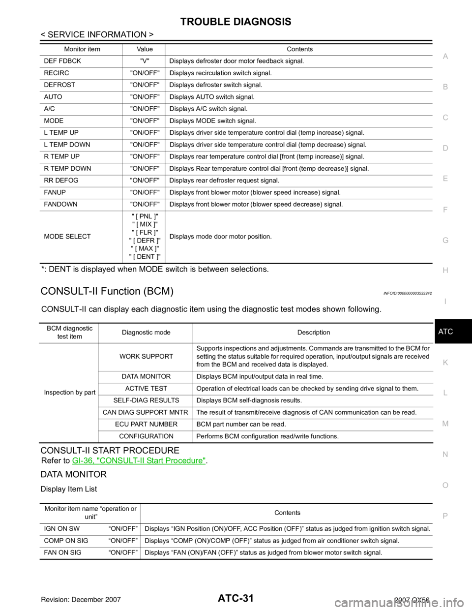
*: DENT is displayed when MODE switch is between selections.
CONSULT-II Function (BCM)INFOID:0000000003533242
CONSULT-II can display each diagnostic item us ing the diagnostic test modes shown following.
CONSULT-II START PROCEDURE
Refer to GI-36, "CONSULT-II Start Procedure".
DATA MONITOR
Display Item List
DEF FDBCK "V" Displays defroster door motor feedback signal.
RECIRC "ON/OFF" Disp lays recirculation switch signal.
DEFROST "ON/OFF" Displays defroster switch signal.
AUTO "ON/OFF" Displays AUTO switch signal.
A/C "ON/OFF" Displays A/C switch signal.
MODE "ON/OFF" Displays MODE switch signal.
L TEMP UP "ON/OFF" Displays driver side temperature control dial (temp increase) signal.
L TEMP DOWN "ON/OFF" Displays driver side temperature control dial (temp decrease) signal.
R TEMP UP "ON/OFF" Displays rear temperature control dial [front (temp increase)] signal.
R TEMP DOWN "ON/OFF" Displays Rear temperature control dial [front (temp decrease)] signal.
RR DEFOG "ON/OFF" Displays rear defroster request signal.
FANUP "ON/OFF" Displays front blower motor (blower speed increase) signal.
FANDOWN "ON/OFF" Displays front blower motor (blower speed decrease) signal.
MODE SELECT " [ PNL ]"
" [ MIX ]"
" [ FLR ]"
" [ DEFR ]" " [ MAX ]"
" [ DENT ]" Displays mode door motor position.
Monitor item Value Contents
BCM diagnostic
test item Diagnostic mode Description
Inspection by part WORK SUPPORT
Supports inspections and adjustments. Commands are transmitted to the BCM for
setting the status suitable for required operation, input/output signals are received
from the BCM and received data is displayed.
DATA MONITOR Displays BCM input/output data in real time. ACTIVE TEST Operation of electrical loads can be checked by sending drive signal to them.
SELF-DIAG RESULTS Displays BCM self-diagnosis results.
CAN DIAG SUPPORT MNTR The result of transmit/receive diagnosis of CAN communication can be read. ECU PART NUMBER BCM part number can be read.
CONFIGURATION Performs BCM configuration read/write functions.
Monitor item name “operation or unit” Contents
IGN ON SW “ON/OFF” Displays “IGN Position (ON)/OFF, ACC Position (OFF)” status as judged from ignition switch signal.
COMP ON SIG “ON/OFF” Displays “COMP (ON)/COMP (OFF)” stat us as judged from air conditioner switch signal.
FAN ON SIG “ON/OFF” Displays “FAN (ON)/FAN (OFF)” status as judged from blower motor switch signal.
Page 402 of 3061

ATC-32
< SERVICE INFORMATION >
TROUBLE DIAGNOSIS
How to Perform Trouble Diagnosis for Quick and Accurate Repair
INFOID:0000000003533243
WORK FLOW
SYMPTOM TABLE
Component Parts and Harness Connector LocationINFOID:0000000003533244
ENGINE COMPARTMENT
*1AT C - 5 0 , "Operational Check (Front)"
or AT C - 5 1 , "
Operational Check
(Rear)" .
SHA900E
Symptom Reference Page
A/C system does not come on. Go to Trouble Diagnosis Procedure for A/C System. AT C - 5 2
A/C system display is malfunctioning. Go to Navigation System. AV- 7 3
A/C system cannot be controlled. Go to Self-diagnosis Function.AT C - 4 8 , "
A/C Sys-
tem Self-Diagno-
sis Function"
Air outlet does not change.
Go to Trouble Diagnosis Procedure for Mode Door Motor. AT C - 5 4
Mode door motor is malfunctioning.
Discharge air temperature does not change.
Go to Trouble Diagnosis Procedure for Air Mix Door Motor. AT C - 5 9
Air mix door motor is malfunctioning.
Intake door does not change.
Go to Trouble Diagnosis Procedure for Intake Door Motor. AT C - 7 0
Intake door motor is malfunctioning.
Defroster door motor is malfunctioning. Go to Trouble Diagnosis Procedure for Defroster Door Motor. AT C - 7 4
Front blower motor operation is malfunction-
ing.Go to Trouble Diagnosis Procedure for Front Blower Motor.
AT C - 7 8
Rear blower motor operation is malfunction-
ing.Go to Trouble Diagnosis Procedure for Rear Blower Motor.
AT C - 8 5
Rear discharge air temperature and/or air
outlet does not change.Go to Trouble Diagnosis Procedure for Rear Air Control circuit.
AT C - 9 3
Magnet clutch does not engage. Go to Trouble Diagnosis Procedure for Magnet Clutch. AT C - 9 6
Insufficient cooling Go to Trouble Diagnosis Procedure for Insufficient Cooling.AT C - 1 0 0
Insufficient heating Go to Trouble Diagnosis Procedure for Insufficient Heating.AT C - 1 0 8
Noise Go to Trouble Diagnosis Procedure for Noise.AT C - 1 0 9
Self-diagnosis cannot be performed. Go to Trouble Diagnosis Procedure for Self-diagnosis. AT C - 111
Memory function does not operate. Go to Trouble Diagnosis Procedure for Memory Function.AT C - 11 2
Page 404 of 3061

ATC-34
< SERVICE INFORMATION >
TROUBLE DIAGNOSIS
1 Front air control M49, M50 2 Rear blower switch (front) M52 3 In-vehicle sensor M32
4 Intake sensor M146 5 Intake door motor M58 6 Variable blower control M122
7 Air mix door motor (passenger) M143 8 Mode door motor M142 9 Defroster door motor M144
10 Air mix door motor (driver) M147 11 Optical sensor M402
WJIA1969E
Page 417 of 3061
TROUBLE DIAGNOSISATC-47
< SERVICE INFORMATION >
C
DE
F
G H
I
K L
M A
B
AT C
N
O P
Front Air Control Termina l and Reference ValueINFOID:0000000003533247
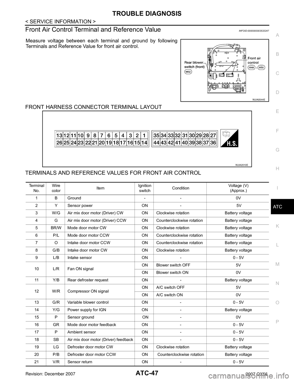
Measure voltage between each terminal and ground by following
Terminals and Reference Value for front air control.
FRONT HARNESS CONNECTOR TERMINAL LAYOUT
TERMINALS AND REFERENCE VALUES FOR FRONT AIR CONTROL
WJIA0544E
WJIA2010E
Te r m i n a l
No. Wire
color ItemIgnition
switch Condition Voltage (V)
(Approx.)
1 B Ground - - 0V
2 Y Sensor power ON - 5V
3 W/G Air mix door motor (Driver) CW ON Clockwise rotation Battery voltage
4 G Air mix door motor (Driver) CCW ON Coun terclockwise rotation Battery voltage
5 BR/W Mode door motor CW ON Clockwise rotation Battery voltage
6 P/L Mode door motor CCW ON Counterclockw ise rotation Battery voltage
7 O Intake door motor CCW ON Counterclockwise rotation Battery voltage
8 G/B Intake door motor CW ON Clockwise rotation Battery voltage
9 L/B Intake sensor ON - 0 - 5V
10 L/R Fan ON signal ON Blower switch OFF 5V
ON Blower switch ON 0V
11 Y/B Rear defroster requ est ON - Battery voltage
12 W/R Compressor ON signal ON A/C switch OFF 5V
ON A/C switch ON 0V
13 G/R Variable blower control ON - 0 - 5V
14 Y/G Power supply for IGN ON - Battery voltage
15 P Sensor ground ON - 0V
16 GR Mode door motor feedback ON - 0 - 5V
17 P Ambient sensor ON - 0 - 5V
18 SB Air mix door motor (D river) feedback ON - 0 - 5V
19 LG Defroster door motor CW ON Clockwise rotation Battery voltage
20 P/B Defroster door motor CCW ON Counterclockwise rotation Battery voltage
21 V/R Sensor return ON - 0 - 5V
Page 418 of 3061
ATC-48
< SERVICE INFORMATION >
TROUBLE DIAGNOSIS
A/C System Self-Diagnosis Function
INFOID:0000000003533248
DESCRIPTION
22 Y/R Power supply for BAT - - Battery voltage
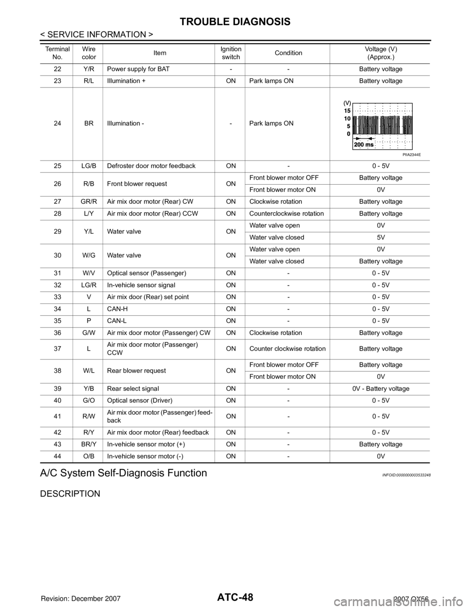
23 R/L Illumination + ON Park lamps ON Battery voltage
24 BR Illumination - - Park lamps ON
25 LG/B Defroster door motor feedback ON - 0 - 5V
26 R/B Front blower request ON Front blower motor OFF Battery voltage
Front blower motor ON 0V
27 GR/R Air mix door motor (Rear) CW ON Clockwise rotation Battery voltage
28 L/Y Air mix door motor (Rear) CCW ON Coun terclockwise rotation Battery voltage
29 Y/L Water valve ON Water valve open 0V
Water valve closed 5V
30 W/G Water valve ON Water valve open 0V
Water valve closed Battery voltage
31 W/V Optical sensor (Passenger) ON - 0 - 5V
32 LG/R In-vehicle sensor signal ON - 0 - 5V
33 V Air mix door (Rear) set point ON - 0 - 5V
34 L CAN-H ON - 0 - 5V
35 P CAN-L ON - 0 - 5V
36 G/W Air mix door motor (Passenger) CW ON Clockwise rotation Battery voltage
37 L Air mix door motor (Passenger)
CCW ON Counter clockwise rotation Battery voltage
38 W/L Rear blower request ON Front blower motor OFF Battery voltage
Front blower motor ON 0V
39 Y/B Rear select signal ON - 0V - Battery voltage
40 G/O Optical sensor (Driver) ON - 0 - 5V
41 R/W Air mix door motor (Passenger) feed-
back ON - 0 - 5V
42 R/Y Air mix door motor (Rear) feedback ON - 0 - 5V
43 BR/Y In-vehicle sensor motor (+) ON - Battery voltage
44 O/B In-vehicle sensor motor (-) ON - 0V
Te r m i n a l
No. Wire
color ItemIgnition
switch Condition Voltage (V)
(Approx.)
PIIA2344E