INFINITI QX56 2008 Factory Service Manual
QX56 2008
INFINITI
INFINITI
https://www.carmanualsonline.info/img/42/57030/w960_57030-0.png
INFINITI QX56 2008 Factory Service Manual
Trending: Cooling system pressure test, dead battery, fuel consumption, immobilizer, Ec-384, fuse box, maintenance schedule
Page 2831 of 4083
PG-64
< COMPONENT DIAGNOSIS >
ELECTRICAL UNITS LOCATION
PASSENGER COMPARTMENT
AAMIA0227GB
Revision: March 20102008 QX56
Page 2832 of 4083
PG
HARNESS CONNECTORPG-65
< COMPONENT DIAGNOSIS >
C
DE
F
G H
I
J
K L
B A
O P
N
HARNESS CONNECTOR
DescriptionINFOID:0000000001744676
HARNESS CONNECTOR (TAB-LOCKING TYPE)
• The tab-locking type connectors help prevent accidental looseness or disconnection.
• The tab-locking type connectors are disconnected by pushi
ng or lifting the locking tab(s). Refer to the figure
below.
Refer to the next page for description of the slide-locking type connector.
CAUTION:
Do not pull the harness or wires when disconnecting the connector.
[Example]
HARNESS CONNECTOR (SLIDE-LOCKING TYPE)
• A new style slide-locking type connector is used on certain systems and components, especially those related to OBD.
• The slide-locking type connectors help prevent incomplete locking and accidental looseness or disconnec- tion.
SEL769DA
Revision: March 2010 2008 QX56
Page 2833 of 4083
PG-66
< COMPONENT DIAGNOSIS >
HARNESS CONNECTOR
• The slide-locking type connectors are disconnected by pushing or pulling the slider. Refer to the figure
below.
CAUTION:
• Do not pull the harness or wires when disconnecting the connector.
• Be careful not to damage the connector su pport bracket when disconnecting the connector.
[Example]
HARNESS CONNECTOR (LEVER LOCKING TYPE)
• Lever locking type harness connectors are used on certain control units and control modules such as ECM, ABS actuator and electric unit (control unit), etc.
• Lever locking type harness connectors are also used on super multiple junction (SMJ) connectors.
• Always confirm the lever is fully locked in place by moving the lever as far as it will go to ensure full connec-
tion.
CAUTION:
SEL769V
Revision: March 2010 2008 QX56
Page 2834 of 4083

PG
HARNESS CONNECTORPG-67
< COMPONENT DIAGNOSIS >
C
DE
F
G H
I
J
K L
B A
O P
N
• Always confirm the lever is full
y released (loosened) before attempting to disconnect or connect
these connectors to avoid damage to the connector housing or terminals.
HARNESS CONNECTOR (DIRECT-CONNECT SRS COMPONENT TYPE)
• SRS direct-connect type harness connectors are used on certain SRS components such as air bag modules
and seat belt pre-tensioners.
• Always pull up to release black locking tab prior to removing connector from SRS components.
• Always push down to lock black locking tab after in stalling connector to SRS components. When locked, the
black locking tab is level with the connector housing.
CAUTION:
• Do not pull the harness or wir es when removing connectors
from SRS components.
1. Control unit with single lever 2. Control unit with dual lever 3. SMJ connector
A. Fasten A. FastenA. Fasten
B.Loosen B.LoosenB.Loosen
C.Lever C.Lever C.Lever
LKIA0670E
WHIA0103E
Revision: March 2010 2008 QX56
Page 2835 of 4083
PG-68
< COMPONENT DIAGNOSIS >
STANDARDIZED RELAY
STANDARDIZED RELAY
DescriptionINFOID:0000000001744677
NORMAL OPEN, NORMAL CLOSED AND MIXED TYPE RELAYS
Relays can mainly be divided into three types: normal open, normal closed and mixed type relays.
TYPE OF STANDARDIZED RELAYS
SEL881H
1M ···················· 1 Make 2M ···················· 2 Make
1T ···················· 1 Transfer 1M·1B ···················· 1 Make 1 Break
SEL882H
Revision: March 2010 2008 QX56
Page 2836 of 4083
PG
STANDARDIZED RELAYPG-69
< COMPONENT DIAGNOSIS >
C
DE
F
G H
I
J
K L
B A
O P
N
SEL188W
Revision: March 2010
2008 QX56
Page 2837 of 4083
PG-70
< COMPONENT DIAGNOSIS >
FUSE BLOCK - JUNCTION BOX (J/B)
FUSE BLOCK - JUNCTION BOX (J/B)
Terminal ArrangementINFOID:0000000001744678
AWMIA0898GB
Revision: March 20102008 QX56
Page 2838 of 4083
PG
FUSE, FUSIBLE LINK AND RELAY BOXPG-71
< COMPONENT DIAGNOSIS >
C
DE
F
G H
I
J
K L
B A
O P
N
FUSE, FUSIBLE LINK AND RELAY BOX
Terminal ArrangementINFOID:0000000001744679
FUSE AND FUSIBLE LINK BOX
AAMIA0217GB
Revision: March 2010
2008 QX56
Page 2839 of 4083
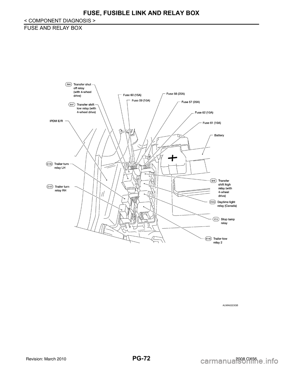
PG-72
< COMPONENT DIAGNOSIS >
FUSE, FUSIBLE LINK AND RELAY BOX
FUSE AND RELAY BOX
ALMIA0223GB
Revision: March 20102008 QX56
Page 2840 of 4083
PG
BATTERYPG-73
< ON-VEHICLE REPAIR >
C
DE
F
G H
I
J
K L
B A
O P
N
ON-VEHICLE REPAIR
BATTERY
Removal and InstallationINFOID:0000000001538891
REMOVAL
1. Disconnect the negative battery terminal (1) and positive battery
terminal (2).
CAUTION:
Remove negative battery terminal first.
2. Remove the battery cover.
3. Remove the battery clamp bolt (3) and battery clamp.
4. Remove the battery.
INSTALLATION
Installation is in the reverse order of removal.
CAUTION:
When installing, in stall the positive battery terminal first.
Reset electronic systems as necessary. Refer to PG-8, "
ADDITIONAL SERVICE WHEN REMOVING BAT-
TERY NEGATIVE TERMINAL : Special Repair Requirement".
⇐
: Front
AWBIA0504ZZ
Battery clamp bolt : 14.7 N·m (1.5 kg-m, 11 ft-lb)
Battery terminal nut : 3.5 N·m (0.36 kg-m, 31 in-lb)
Revision: March 2010 2008 QX56
Trending: 4 wheel drive, keyless entry, fuel pump, fuse, audio, Brake booster, instrument panel


