battery INFINITI QX56 2008 Factory Service Manual
[x] Cancel search | Manufacturer: INFINITI, Model Year: 2008, Model line: QX56, Model: INFINITI QX56 2008Pages: 4083, PDF Size: 81.73 MB
Page 2087 of 4083

PRECAUTIONSFAX-3
< PRECAUTION >
CEF
G H
I
J
K L
M A
B
FA X
N
O P
5. When the repair work is completed, return the ignition switch to the ″LOCK ″ position before connecting
the battery cables. (At this time, the steering lock mechanism will engage.)
6. Perform a self-diagnosis check of al l control units using CONSULT-III.
PrecautionINFOID:0000000001534446
Observe the following precautions when disassembling and servicing the wheel hub and drive shafts.
• Perform work in a location which is as dust-free as possible.
• Before disassembling and servicing, clean the outside of parts.
• Prevention of the entry of foreign objects must be taken into account during disassembly of the component
parts.
• Disassembled parts must be carefully reassembled in the correct order. If work is interrupted, a clean cover
must be placed over parts.
• Paper shop cloths must be used. Fabric shop cloths must not be used because of the danger of lint adhering to parts.
• Disassembled parts (except for rubber parts) should be cleaned with a suitable solvent which shall be removed by blowing with air or wiping with paper shop cloths.
Revision: March 2010 2008 QX56
Page 2101 of 4083

FL-1
ENGINE
C
DE
F
G H
I
J
K L
M
SECTION FL
A
FL
N
O P
CONTENTS
FUEL SYSTEM
PRECAUTION ....... ........................................2
PRECAUTIONS .............................................. .....2
Precaution for Supplemental Restraint System
(SRS) "AIR BAG" and "SEAT BELT PRE-TEN-
SIONER" ............................................................. ......
2
Precaution Necessary for Steering Wheel Rota-
tion After Battery Disconnect ............................... ......
2
FUEL SYSTEM ....................................................4
General Precaution ............................................. ......4
PREPARATION ............................................5
PREPARATION .............................................. .....5
Special Service Tool ........................................... ......5
Commercial Service Tool ..........................................5
BASIC INSPECTION ....................................6
FUEL SYSTEM ............................................... .....6
Checking Fuel Line ............................................. ......6
REMOVAL AND INSTALLATION ................7
FUEL LEVEL SENSOR UNIT, FUEL FILTER
AND FUEL PUMP ASSEMBLY .........................
7
Removal and Installation ..................................... .....7
FUEL TANK ......................................................11
Removal and Installation ..................................... ....11
DISASSEMBLY AND ASSEMBLY ..............16
FUEL LEVEL SENSOR UNIT, FUEL FILTER
AND FUEL PUMP ASSEMBLY ........................
16
Disassembly and Assembly ................................. ....16
SERVICE DATA AND SPECIFICATIONS
(SDS) ............... .......................................... ...
17
SERVICE DATA AND SPECIFICATIONS
(SDS) .................................................................
17
Standard and Limit .............................................. ....17
Revision: March 2010 2008 QX56
Page 2102 of 4083

FL-2
< PRECAUTION >
PRECAUTIONS
PRECAUTION
PRECAUTIONS
Precaution for Supplemental Restraint System (SRS) "AIR BAG" and "SEAT BELT
PRE-TENSIONER"
INFOID:0000000004900804
The Supplemental Restraint System such as “A IR BAG” and “SEAT BELT PRE-TENSIONER”, used along
with a front seat belt, helps to reduce the risk or severity of injury to the driver and front passenger for certain
types of collision. This system includes seat belt switch inputs and dual stage front air bag modules. The SRS
system uses the seat belt switches to determine the front air bag deployment, and may only deploy one front
air bag, depending on the severity of a collision and w hether the front occupants are belted or unbelted.
Information necessary to service the system safely is included in the SR and SB section of this Service Man-
ual.
WARNING:
• To avoid rendering the SRS inopera tive, which could increase the risk of personal injury or death in
the event of a collision which would result in air bag inflation, all maintenance must be performed by
an authorized NISSAN/INFINITI dealer.
• Improper maintenance, including in correct removal and installation of the SRS, can lead to personal
injury caused by unintent ional activation of the system. For re moval of Spiral Cable and Air Bag
Module, see the SR section.
• Do not use electrical test equipmen t on any circuit related to the SRS unless instructed to in this
Service Manual. SRS wiring harn esses can be identified by yellow and/or orange harnesses or har-
ness connectors.
PRECAUTIONS WHEN USING POWER TOOLS (AIR OR ELECTRIC) AND HAMMERS
WARNING:
• When working near the Airbag Diagnosis Sensor Unit or other Airbag System sensors with the Igni-
tion ON or engine running, DO NOT use air or electri c power tools or strike near the sensor(s) with a
hammer. Heavy vibration could activate the sensor( s) and deploy the air bag(s), possibly causing
serious injury.
• When using air or electric power tools or hammers , always switch the Ignition OFF, disconnect the
battery, and wait at least 3 minu tes before performing any service.
Precaution Necessary for Steering W heel Rotation After Battery Disconnect
INFOID:0000000004900803
NOTE:
• This Procedure is applied only to models with Intelligent Key system and NATS (NISSAN ANTI-THEFT SYS-
TEM).
• Remove and install all control units after disconnecting both battery cables with the ignition knob in the
″LOCK ″ position.
• Always use CONSULT-III to perform self-diagnosis as a part of each function inspection after finishing work.
If DTC is detected, perform trouble diagnosis according to self-diagnostic results.
For models equipped with the Intelligent Key system and NATS, an electrically controlled steering lock mech-
anism is adopted on the key cylinder.
For this reason, if the battery is disconnected or if the battery is discharged, the steering wheel will lock and
steering wheel rotation will become impossible.
If steering wheel rotation is required when battery pow er is interrupted, follow the procedure below before
starting the repair operation.
OPERATION PROCEDURE
1. Connect both battery cables. NOTE:
Supply power using jumper cables if battery is discharged.
2. Use the Intelligent Key or mechanical key to turn the ignition switch to the ″ACC ″ position. At this time, the
steering lock will be released.
3. Disconnect both battery cables. The steering lock will remain released and the steering wheel can be rotated.
4. Perform the necessary repair operation.
Revision: March 2010 2008 QX56
Page 2103 of 4083

PRECAUTIONSFL-3
< PRECAUTION >
C
DE
F
G H
I
J
K L
M A
FL
NP
O
5. When the repair work is completed, return the ignition switch to the
″LOCK ″ position before connecting
the battery cables. (At this time, the steering lock mechanism will engage.)
6. Perform a self-diagnosis check of al l control units using CONSULT-III.
Revision: March 2010 2008 QX56
Page 2104 of 4083

FL-4
< PRECAUTION >
FUEL SYSTEM
FUEL SYSTEM
General PrecautionINFOID:0000000001534428
WARNING:
When replacing fuel line parts, be sure to observe the following.
• Put a “CAUTION: INFLAMMABLE” sign in the workshop.
• Be sure to work in a well ventilate d area and furnish workshop with a CO
2 fire extinguisher.
• Do not smoke while servicing fuel system. Keep open flames and sparks away from the work area.
CAUTION:
• Before removing fuel line parts, carry out the following procedures:
- Put drained fuel in an explosi on-proof container and put the lid on securely. Keep the container in
safe area.
- Release fuel pressure from the fuel lines. Refer to EC-494, "
Fuel Pressure Check" .
- Disconnect the battery negative terminal.
• Always replace O-rings and clamps with new ones.
• Do not kink or twist hoses when they are being installed.
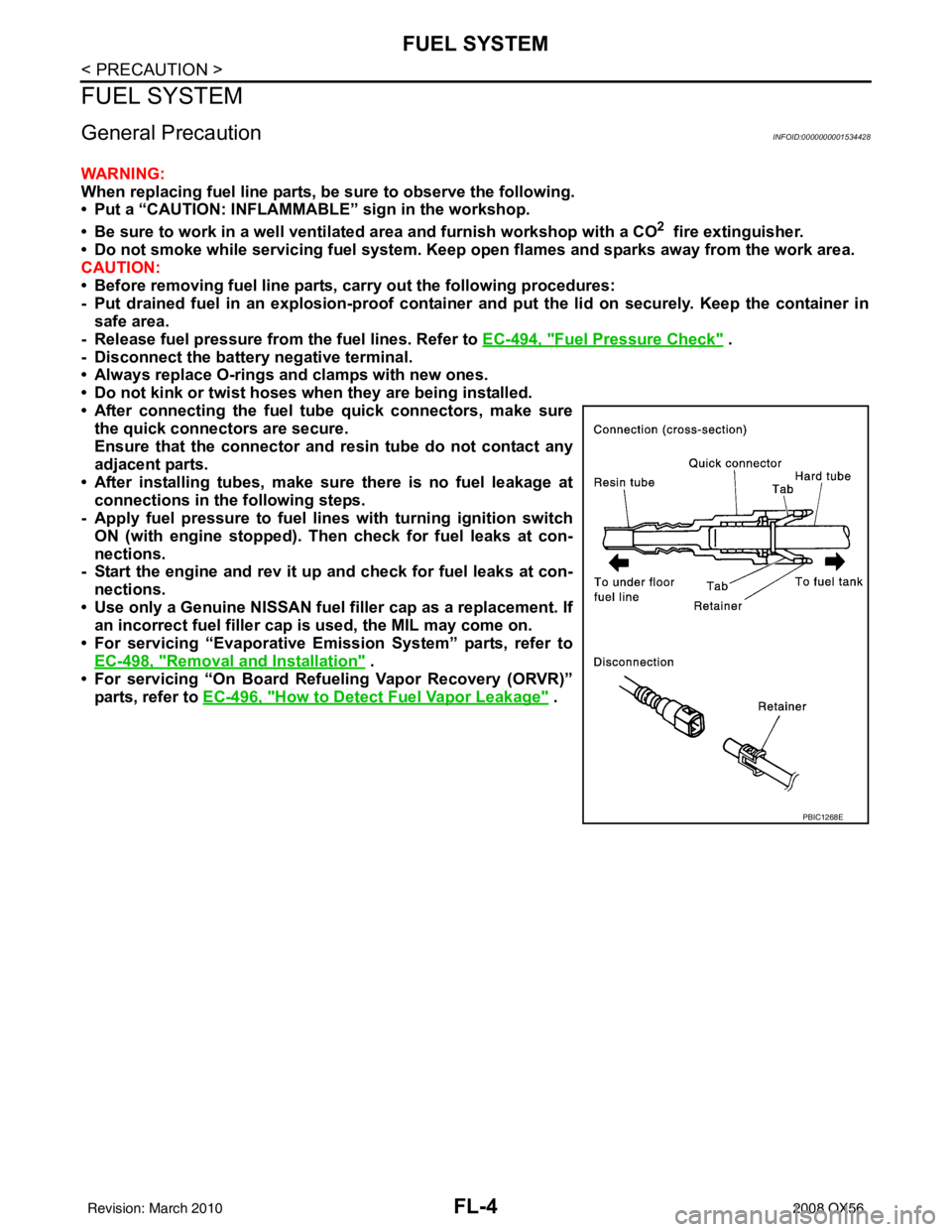
• After connecting the fuel t ube quick connectors, make sure
the quick connectors are secure.
Ensure that the connector and resin tube do not contact any
adjacent parts.
• After installing tubes, make su re there is no fuel leakage at
connections in the following steps.
- Apply fuel pressure to fuel lines with turning ignition switch
ON (with engine stopped). Th en check for fuel leaks at con-
nections.
- Start the engine and rev it up and check for fuel leaks at con-
nections.
• Use only a Genuine NISSAN fuel filler cap as a replacement. If an incorrect fuel filler cap is used, the MIL may come on.
• For servicing “Evaporative Emission System” parts, refer to EC-498, "
Removal and Installation" .
• For servicing “On Board Refueling Vapor Recovery (ORVR)”
parts, refer to EC-496, "
How to Detect Fuel Vapor Leakage" .
PBIC1268E
Revision: March 2010 2008 QX56
Page 2108 of 4083

FL-8
< REMOVAL AND INSTALLATION >
FUEL LEVEL SENSOR UNIT, FUEL FILTER AND FUEL PUMP ASSEMBLY
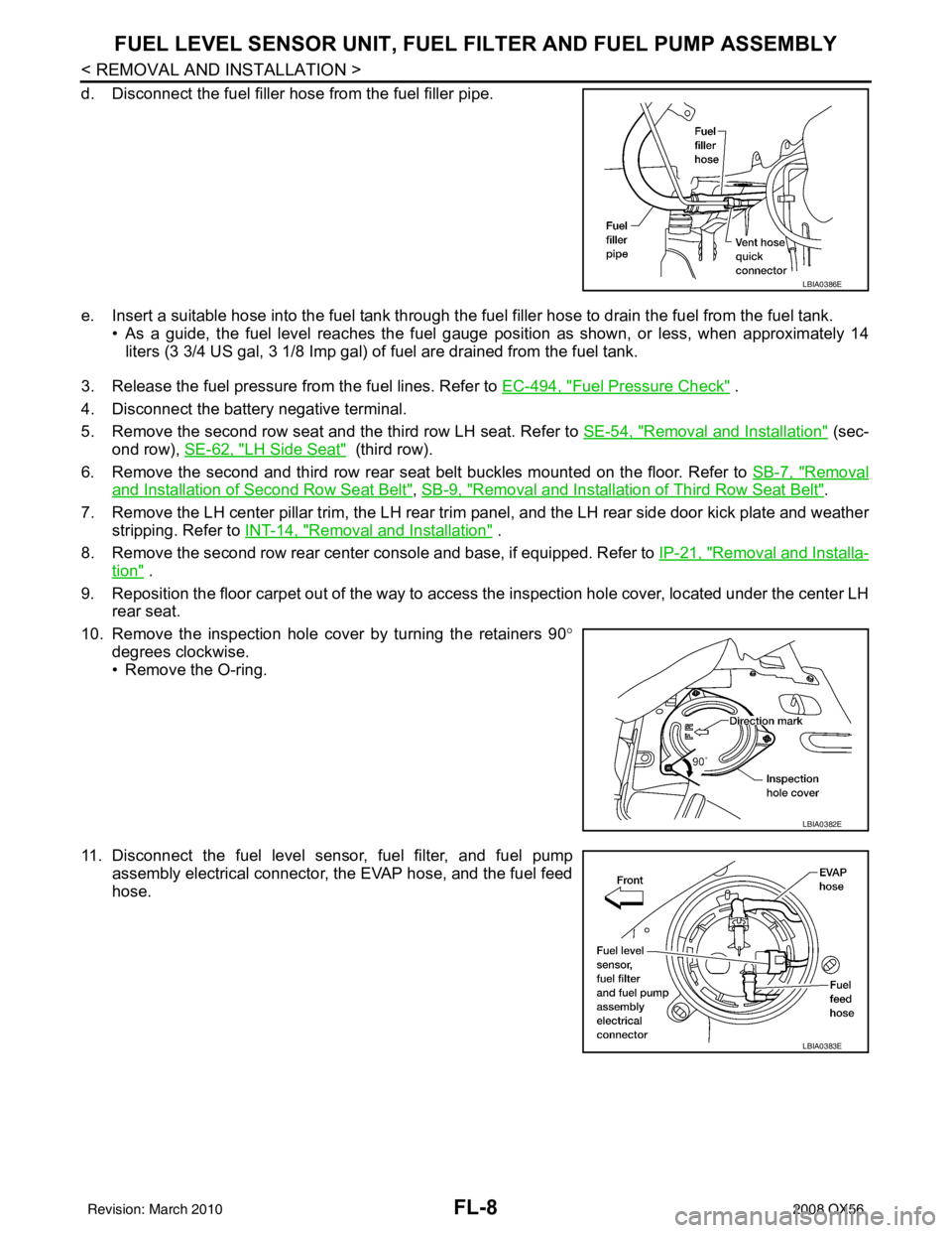
d. Disconnect the fuel filler hose from the fuel filler pipe.
e. Insert a suitable hose into the fuel tank through the fuel filler hose to drain the fuel from the fuel tank.
• As a guide, the fuel level reaches the fuel gauge position as shown, or less, when approximately 14
liters (3 3/4 US gal, 3 1/8 Imp gal) of fuel are drained from the fuel tank.
3. Release the fuel pressure from the fuel lines. Refer to EC-494, "
Fuel Pressure Check" .
4. Disconnect the battery negative terminal.
5. Remove the second row seat and the third row LH seat. Refer to SE-54, "
Removal and Installation" (sec-
ond row), SE-62, "
LH Side Seat" (third row).
6. Remove the second and third row rear seat belt buckles mounted on the floor. Refer to SB-7, "
Removal
and Installation of Second Row Seat Belt", SB-9, "Removal and Installation of Third Row Seat Belt".
7. Remove the LH center pillar trim, the LH rear trim panel, and the LH rear side door kick plate and weather
stripping. Refer to INT-14, "
Removal and Installation" .
8. Remove the second row rear center console and base, if equipped. Refer to IP-21, "
Removal and Installa-
tion" .
9. Reposition the floor carpet out of the way to access the inspection hole cover, located under the center LH
rear seat.
10. Remove the inspection hole cover by turning the retainers 90 °
degrees clockwise.
• Remove the O-ring.
11. Disconnect the fuel level sensor, fuel filter, and fuel pump assembly electrical connector, the EVAP hose, and the fuel feed
hose.
LBIA0386E
LBIA0382E
LBIA0383E
Revision: March 2010 2008 QX56
Page 2109 of 4083

FUEL LEVEL SENSOR UNIT, FUEL FILTER AND FUEL PUMP ASSEMBLYFL-9
< REMOVAL AND INSTALLATION >
C
DE
F
G H
I
J
K L
M A
FL
NP
O
Disconnect the quick connector as follows:
• Hold the sides of the connector, push in tabs and pull out the
tube.
• If the connector and the tube are stuck together, push and pull several times until they start to move. Then disconnect them
by pulling.
CAUTION:
• The quick connector can be disconnected when the tabs
are completely depressed. Do not twist the quick connec-
tor more than necessary.
• Do not use any tools to di sconnect the quick connector.
• Keep the resin tube away from heat. Be especially careful
when welding near the tube.
• Prevent any acid liquids such as battery electrolyte, from getting on the resin tube.
• Do not bend or twist the resin tube during connection.
• Do not remove the remaining retainer on the hard tube (or the equivalent) except when the resin tube or the retainer
is replaced.
• When the resin tube or hard tube, or the equivalent, is replaced, also replace the retainer with a new one (white
colored retainer).
• To keep the quick connector clean and to avoid damage
and contamination from foreign materials, cover the quick
connector with plastic bags or suitable material as shown.
SFE562A
PBIC1268E
PBIC0163E
Revision: March 2010 2008 QX56
Page 2112 of 4083

FL-12
< REMOVAL AND INSTALLATION >
FUEL TANK
REMOVAL
WARNING:
Follow the “General Precautions” before working on the fuel system. Refer to FL-4, "
General Precau-
tion" .
1. Drain the fuel from the fuel tank, if necessary. • Position the vehicle so it is level.
2. Remove the fuel filler cap to release the pressure from inside the fuel tank.
3. Check the fuel level on level gauge. If the fuel gauge indicates more than the level as shown (full or almost full), drain the fuel
from the fuel tank until the fuel gauge indicates the level as
shown, or less.
• If the fuel pump does not operate, use the following procedure
to drain the fuel to the specified level after disconnecting the
fuel filler hose from the fuel filler pipe.
a. Insert a suitable hose of less than 15 mm (0.59 in) diameter into the fuel filler pipe through the fuel filler opening to drain the fuel
from fuel filler pipe.
b. Insert a suitable hose into the fuel tank through the fuel filler hose to drain the fuel from the fuel tank.
• As a guide, the fuel level reaches the fuel gauge position as shown, or less, when approximately 14
liters (3 3/4 US gal, 3 1/8 Imp gal) of fuel are drained from the fuel tank.
4. Remove the LH rear wheel and tire. Refer to WT-48, "
Rotation" .
5. Remove the four clips and remove the rear fender protector, front.
6. Disconnect the fuel filler hose from the fuel filler pipe and dis- connect the vent hose quick connector.
7. Release the fuel pressure from the fuel lines. Refer to EC-494, "
Fuel Pressure Check" .
8. Disconnect the battery negative terminal.
9. Remove the second row seat and the third row LH seat. Refer to SE-54, "
Removal and Installation" (sec-
ond row), SE-62, "
LH Side Seat" (third row).
10. Remove the second and third row rear seat belt buckles mounted on the floor. Refer to SB-7, "
Removal
and Installation of Second Row Seat Belt", SB-9, "Removal and Installation of Third Row Seat Belt".
11. Remove the LH center pillar trim, the LH rear trim panel, and the LH rear side door kick plate and weather
stripping. Refer to INT-14, "
Removal and Installation" .
12. Remove the second row rear center console and base. Refer to IP-21, "
Removal and Installation" .
13. Reposition the floor carpet out of the way to access the inspection hole cover, located under the center LH
rear seat.
13. Fuel filler hose grommet 14. Fuel filler cap 15. Fuel tank shield
16. Clip 17. Fuel filler pipe shield
WBIA0390E
LBIA0386E
Revision: March 2010 2008 QX56
Page 2114 of 4083

FL-14
< REMOVAL AND INSTALLATION >
FUEL TANK
• The quick connector can be disconnected when the tabsare completely depressed. Do not twist the quick connec-
tor more than necessary.
• Do not use any tools to di sconnect the quick connector.
• Keep the resin tube away from heat. Be especially careful
when welding near the tube.
• Prevent any acid liquids such as battery electrolyte, from getting on the resin tube.
• Do not bend or twist the resin tube during connection.
• Do not remove the remaining retainer on the hard tube (or
the equivalent) except when the resin tube or the retainer
is replaced.
• When the resin tube or hard tube, or the equivalent, is
replaced, also replace the retainer with a new one (white
colored retainer).
• To keep the quick connector clean and to avoid damage
and contamination from foreign materials, cover the quick
connector with plastic bags or suit able material as shown.
16. Remove the four bolts and remove the fuel tank shield.
17. Remove the propeller shaft. Refer to DLN-194, "
Removal and Installation".
18. Disconnect fuel filler hose, and vent hose at the fuel tank side.
19. Remove the fuel tank strap bolts while supporting the fuel tank with a suitable lift jack.
20. Disconnect the EVAP hose from the molded clip in the top of the fuel tank while lowering the fuel tank.
21. Lower the fuel tank using a suitable lift jack and remove it.
PBIC1268E
PBIC0163E
LBIA0387E
Revision: March 2010 2008 QX56
Page 2118 of 4083

FSU-1
SUSPENSION
C
DF
G H
I
J
K L
M
SECTION FSU
A
B
FSU
N
O PCONTENTS
FRONT SUSPENSION
PRECAUTION ....... ........................................2
PRECAUTIONS .............................................. .....2
Precaution for Supplemental Restraint System
(SRS) "AIR BAG" and "SEAT BELT PRE-TEN-
SIONER" ............................................................. ......
2
Precaution Necessary for Steering Wheel Rota-
tion After Battery Disconnect ............................... ......
2
Precaution .................................................................3
PREPARATION ............................................4
PREPARATION .............................................. .....4
Special Service Tool ........................................... ......4
Commercial Service Tool ..........................................4
SYMPTOM DIAGNOSIS ...............................6
NOISE, VIBRATION AND HARSHNESS
(NVH) TROUBLESHOOTING ........................ .....
6
NVH Troubleshooting Chart ................................ ......6
ON-VEHICLE MAINTENANCE .....................7
ON-VEHICLE SERVICE ................................. .....7
Front Suspension Parts ....................................... ......7
Front Wheel Alignment ..............................................7
UPPER BALL JOINT AND LOWER BALL
JOINT .................................................................
11
Inspection ............................................................ ....11
KNUCKLE ...................................................... ....13
On-Vehicle Inspection and Service ..................... ....13
ON-VEHICLE REPAIR .................................14
FRONT SUSPENSION ASSEMBLY .............. ....14
Component .......................................................... ....14
REMOVAL AND INSTALLATION ...............15
COIL SPRING AND SHOCK ABSORBER .......15
Removal and Installation ..................................... ....15
Disposal ...................................................................15
STABILIZER BAR .............................................16
Removal and Installation .........................................16
UPPER LINK .....................................................17
Removal and Installation ..................................... ....17
LOWER LINK ....................................................18
Removal and Installation .........................................18
UPPER BALL JOINT AND LOWER BALL
JOINT ................................................................
19
Removal and Installation .........................................19
KNUCKLE .........................................................20
Removal and Installation ..................................... ....20
DISASSEMBLY AND ASSEMBLY ..............22
COIL SPRING AND SHOCK ABSORBER .......22
Disassembly and Assembly ................................. ....22
SERVICE DATA AND SPECIFICATIONS
(SDS) ............... .......................................... ...
24
SERVICE DATA AND SPECIFICATIONS
(SDS) .................................................................
24
General Specification .......................................... ....24
Spring Free Height ..................................................24
Wheel Alignment (Unladen*1) ..................................24
Ball Joint .............................................................. ....25
Wheelarch Height (Unladen*1) ................................25
Revision: March 2010 2008 QX56