lock INFINITI QX56 2009 Factory Service Manual
[x] Cancel search | Manufacturer: INFINITI, Model Year: 2009, Model line: QX56, Model: INFINITI QX56 2009Pages: 4171, PDF Size: 84.65 MB
Page 2219 of 4171
PRECAUTIONSGI-25
< PRECAUTION >
C
DE
F
G H
I
J
K L
M B
GI
N
O P
2. Use the Intelligent Key or mechanical key to turn the ignition switch to the ″ACC ″ position. At this time, the
steering lock will be released.
3. Disconnect both battery cables. The steering lock will remain released and the steering wheel can be
rotated.
4. Perform the necessary repair operation.
5. When the repair work is completed, return the ignition switch to the ″LOCK ″ position before connecting
the battery cables. (At this time, the steering lock mechanism will engage.)
6. Perform a self-diagnosis check of al l control units using CONSULT-III.
Procedures without Cowl Top CoverINFOID:0000000003771198
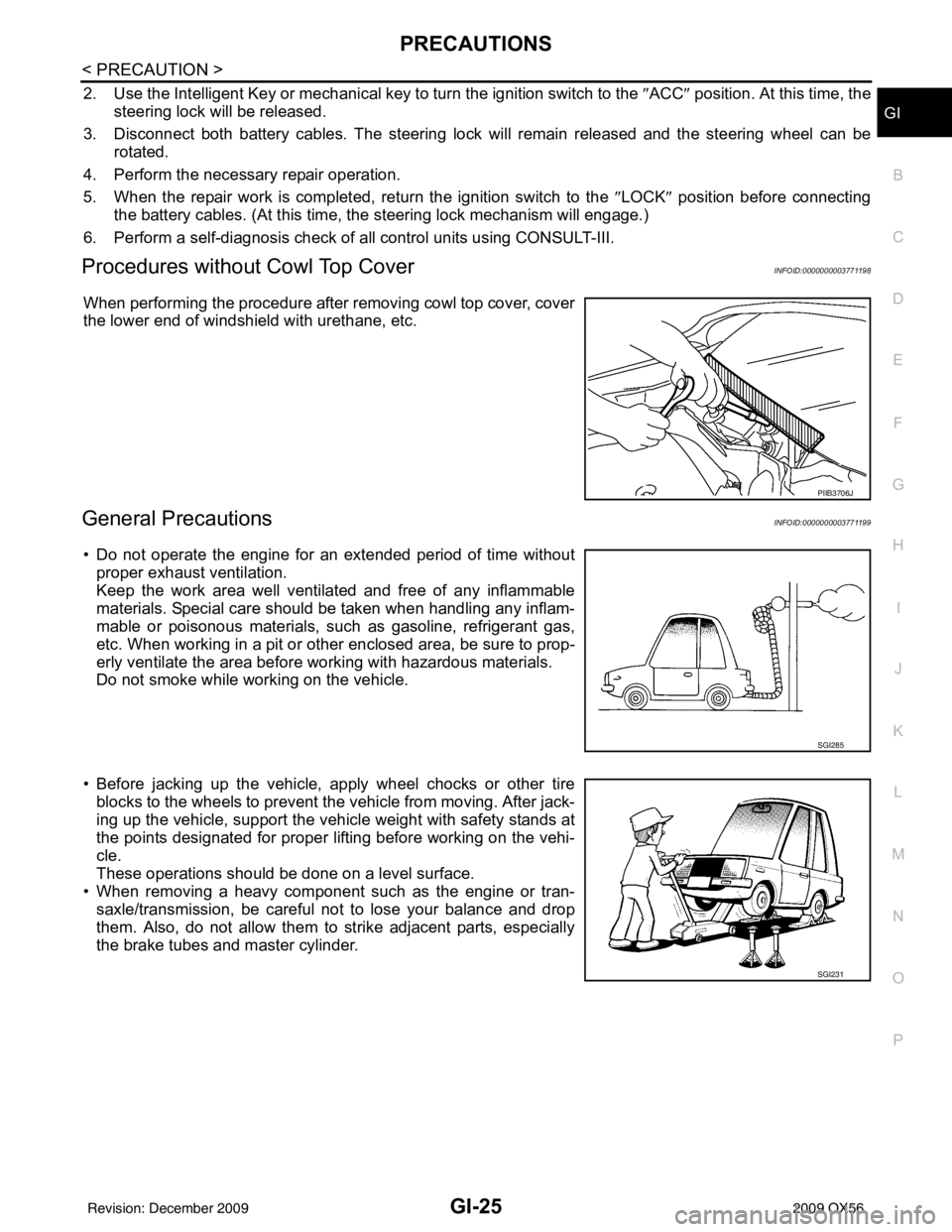
When performing the procedure after removing cowl top cover, cover
the lower end of windshield with urethane, etc.
General PrecautionsINFOID:0000000003771199
• Do not operate the engine for an extended period of time without
proper exhaust ventilation.
Keep the work area well ventilated and free of any inflammable
materials. Special care should be taken when handling any inflam-
mable or poisonous materials, such as gasoline, refrigerant gas,
etc. When working in a pit or ot her enclosed area, be sure to prop-
erly ventilate the area before working with hazardous materials.
Do not smoke while working on the vehicle.
• Before jacking up the vehicle, apply wheel chocks or other tire blocks to the wheels to prevent t he vehicle from moving. After jack-
ing up the vehicle, support the vehicle weight with safety stands at
the points designated for proper lifting before working on the vehi-
cle.
These operations should be done on a level surface.
• When removing a heavy component such as the engine or tran-
saxle/transmission, be careful not to lose your balance and drop
them. Also, do not allow them to strike adjacent parts, especially
the brake tubes and master cylinder.
PIIB3706J
SGI285
SGI231
Revision: December 20092009 QX56
Page 2220 of 4171
GI-26
< PRECAUTION >
PRECAUTIONS
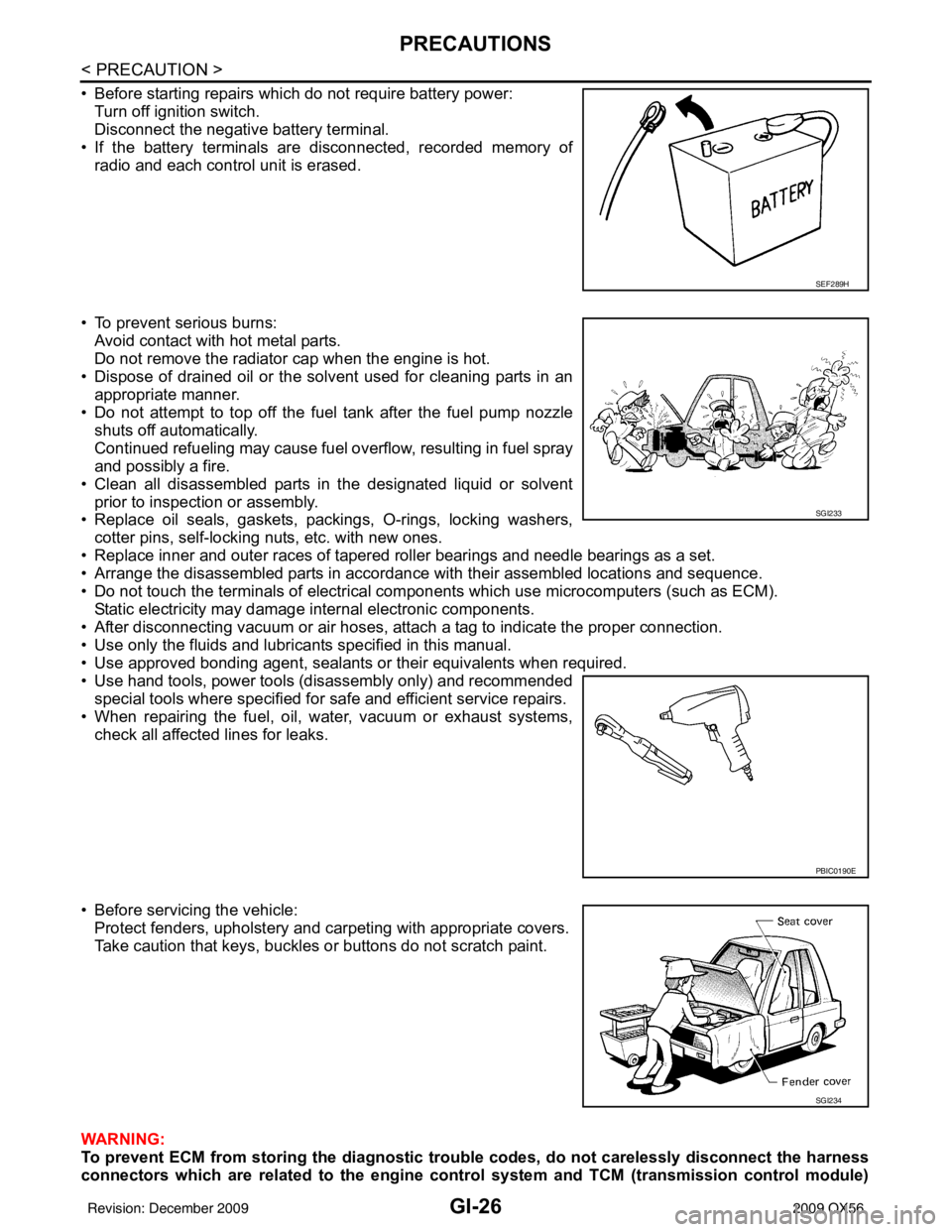
• Before starting repairs which do not require battery power:Turn off ignition switch.
Disconnect the negative battery terminal.
• If the battery terminals are disconnected, recorded memory of radio and each control unit is erased.
• To prevent serious burns: Avoid contact with hot metal parts.
Do not remove the radiator cap when the engine is hot.
• Dispose of drained oil or the solvent used for cleaning parts in an appropriate manner.
• Do not attempt to top off the fuel tank after the fuel pump nozzle
shuts off automatically.
Continued refueling may cause fuel overflow, resulting in fuel spray
and possibly a fire.
• Clean all disassembled parts in the designated liquid or solvent prior to inspection or assembly.
• Replace oil seals, gaskets, packings, O-rings, locking washers,
cotter pins, self-locking nuts, etc. with new ones.
• Replace inner and outer races of tapered roller bearings and needle bearings as a set.
• Arrange the disassembled parts in accordance with their assembled locations and sequence.
• Do not touch the terminals of electrical com ponents which use microcomputers (such as ECM).
Static electricity may damage internal electronic components.
• After disconnecting vacuum or air hoses, atta ch a tag to indicate the proper connection.
• Use only the fluids and lubricants specified in this manual.
• Use approved bonding agent, sealants or their equivalents when required.
• Use hand tools, power tools (disassembly only) and recommended special tools where specified for safe and efficient service repairs.
• When repairing the fuel, oil, water, vacuum or exhaust systems, check all affected lines for leaks.
• Before servicing the vehicle: Protect fenders, upholstery and carpeting with appropriate covers.
Take caution that keys, buckles or buttons do not scratch paint.
WARNING:
To prevent ECM from storing the diagnostic tro uble codes, do not carelessly disconnect the harness
connectors which are related to the engine control system and TCM (transmission control module)
SEF289H
SGI233
PBIC0190E
SGI234
Revision: December 20092009 QX56
Page 2224 of 4171
GI-30
< PRECAUTION >
LIFTING POINT
LIFTING POINT
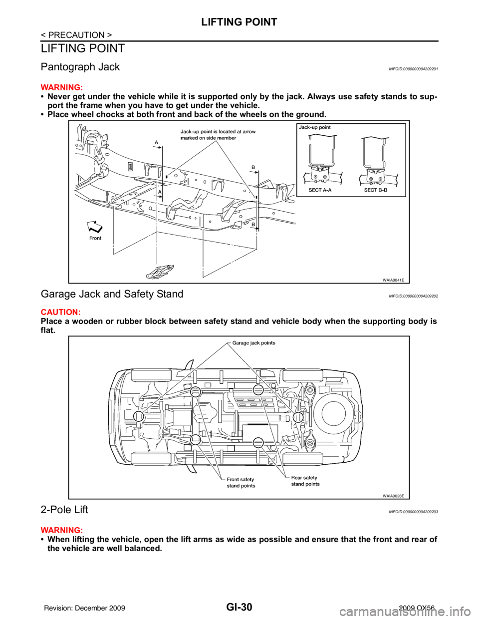
Pantograph JackINFOID:0000000004209201
WARNING:
• Never get under the vehicle while it is supported only by the jack. Always use safety stands to sup-
port the frame when you have to get under the vehicle.
• Place wheel chocks at both front an d back of the wheels on the ground.
Garage Jack and Safety StandINFOID:0000000004209202
CAUTION:
Place a wooden or rubber block between safety stand and vehicle body when the supporting body is
flat.
2-Pole LiftINFOID:0000000004209203
WARNING:
• When lifting the vehicle, open the lift arms as wid e as possible and ensure that the front and rear of
the vehicle are well balanced.
WAIA0041E
WAIA0028E
Revision: December 20092009 QX56
Page 2226 of 4171
GI-32
< PRECAUTION >
TOW TRUCK TOWING
TOW TRUCK TOWING
Tow Truck TowingINFOID:0000000005867507
WARNING:
• Never get under the vehicle while it is supported only by the jack. Always use safety stands to sup-
port the frame when you have to get under the vehicle.
• Place wheel chocks at both front an d back of the wheels on the ground.
CAUTION:
• All applicable State or Provincial (in Canada) laws and local laws regarding the towing operation
must be obeyed.
• It is necessary to use proper towing equipment to avoid possible damage during towing operation.
Towing is in accordance with Towing Procedure Manual at dealer.
• Always attach safety chains before towing.
• When towing, make sure that the transmission, steering system and powertrain are in good order. If any unit is damaged, dollies must be used.
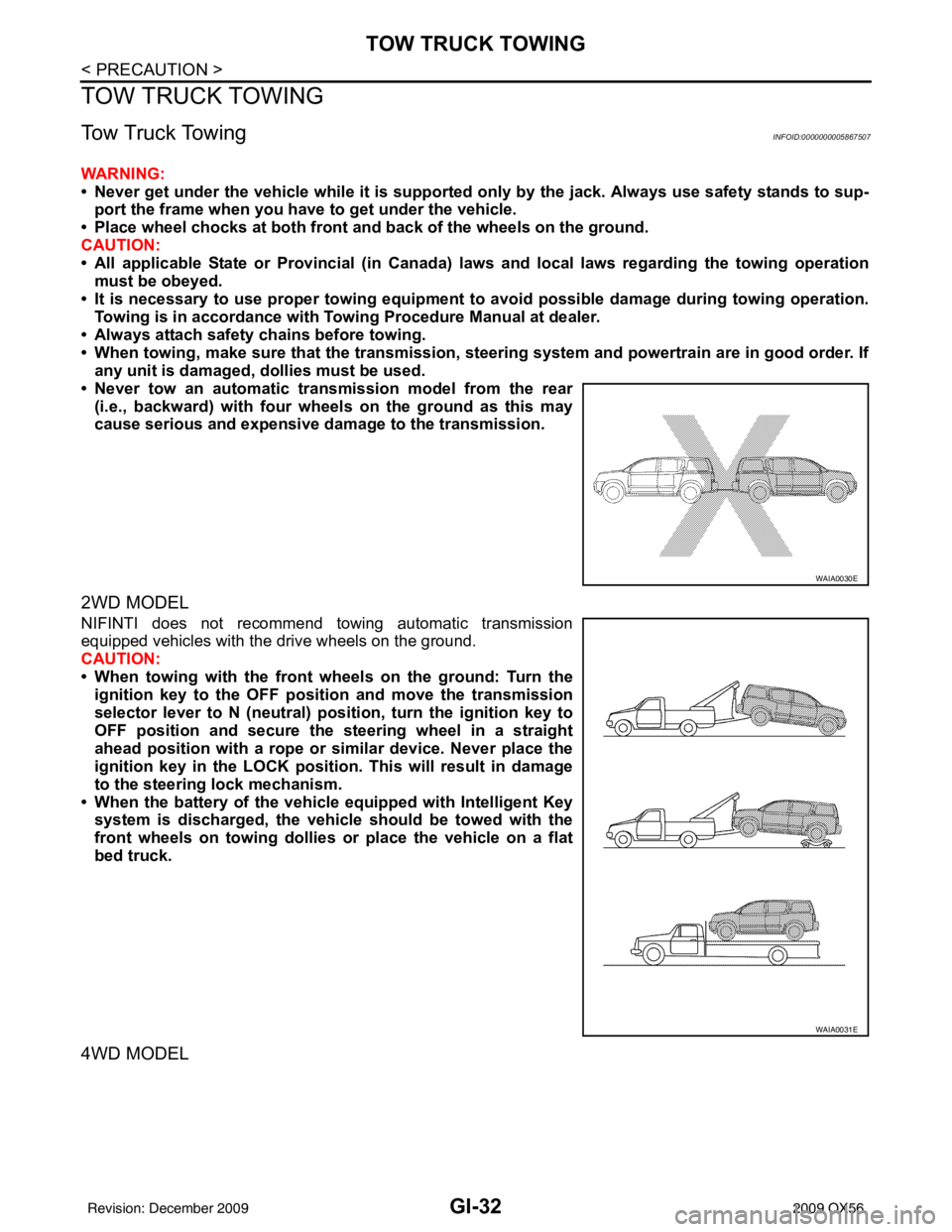
• Never tow an automatic transmission model from the rear (i.e., backward) with four wh eels on the ground as this may
cause serious and expensive dama ge to the transmission.
2WD MODEL
NIFINTI does not recommend towing automatic transmission
equipped vehicles with the drive wheels on the ground.
CAUTION:
• When towing with the front wheels on the ground: Turn the
ignition key to the OFF posit ion and move the transmission
selector lever to N (neutral) pos ition, turn the ignition key to
OFF position and secure the steering wheel in a straight
ahead position with a rope or similar device. Never place the
ignition key in the LOCK position. This will result in damage
to the steering lock mechanism.
• When the battery of the vehicle equipped with Intelligent Key system is discharged, the vehicle should be towed with the
front wheels on towing dollies or place the vehicle on a flat
bed truck.
4WD MODEL
WAIA0030E
WAIA0031E
Revision: December 20092009 QX56
Page 2232 of 4171
GI-38
< BASIC INSPECTION >
SERVICE INFORMATION FOR ELECTRICAL INCIDENT
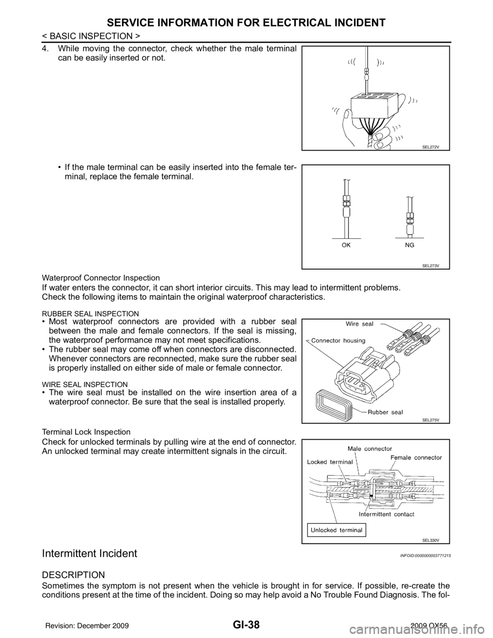
4. While moving the connector, check whether the male terminalcan be easily inserted or not.
• If the male terminal can be easily inserted into the female ter-minal, replace the female terminal.
Waterproof Connector Inspection
If water enters the connector, it can short interior circuits. This may lead to intermittent problems.
Check the following items to maintain the original waterproof characteristics.
RUBBER SEAL INSPECTION• Most waterproof connectors are provided with a rubber seal between the male and female connectors. If the seal is missing,
the waterproof performance may not meet specifications.
• The rubber seal may come off when connectors are disconnected.
Whenever connectors are reconnected, make sure the rubber seal
is properly installed on either side of male or female connector.
WIRE SEAL INSPECTION• The wire seal must be installed on the wire insertion area of awaterproof connector. Be sure that the seal is installed properly.
Terminal Lock Inspection
Check for unlocked terminals by pulling wire at the end of connector.
An unlocked terminal may create intermittent signals in the circuit.
Intermittent IncidentINFOID:0000000003771215
DESCRIPTION
Sometimes the symptom is not present when the vehicle is brought in for service. If possible, re-create the
conditions present at the time of the incident. Doi ng so may help avoid a No Trouble Found Diagnosis. The fol-
SEL272V
SEL273V
SEL275V
SEL330V
Revision: December 20092009 QX56
Page 2235 of 4171
SERVICE INFORMATION FOR ELECTRICAL INCIDENTGI-41
< BASIC INSPECTION >
C
DE
F
G H
I
J
K L
M B
GI
N
O P
Circuit InspectionINFOID:0000000003771216
DESCRIPTION
• In general, testing electrical circuits is an easy task if it is approached in a logical and organized method. Before beginning it is important to have all available information on the system to be tested. Also, get a thor-
ough understanding of system operation. Then you will be able to use the appropriate equipment and follow
the correct test procedure.
• You may have to simulate vehicle vibrations while te sting electrical components. Gently shake the wiring
harness or electrical component to do this.
NOTE:
Refer to GI-35, "
How to Check Terminal" to probe or check terminal.
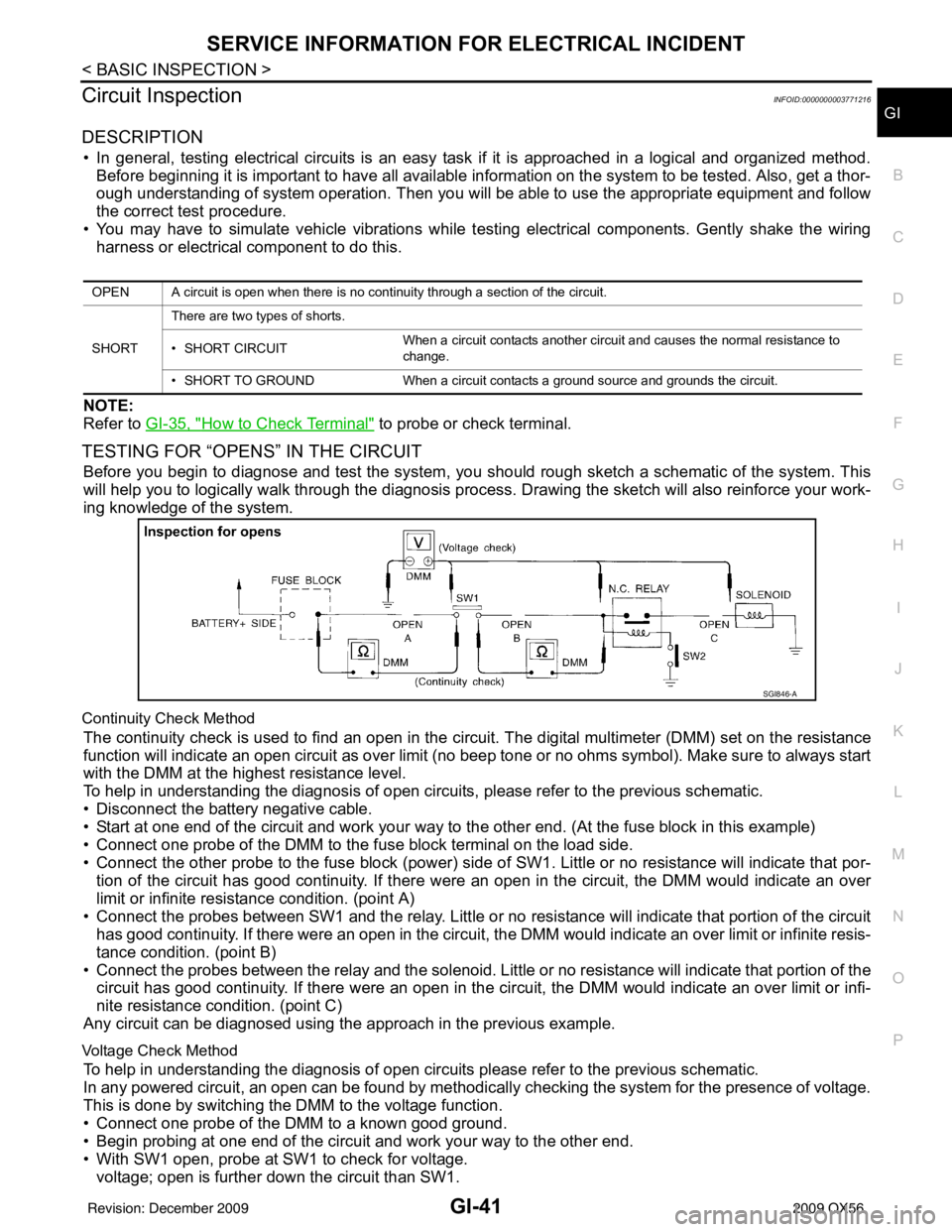
TESTING FOR “OPENS” IN THE CIRCUIT
Before you begin to diagnose and test the system, you should rough sketch a schematic of the system. This
will help you to logically walk through the diagnosis process. Drawing the sketch will also reinforce your work-
ing knowledge of the system.
Continuity Check Method
The continuity check is used to find an open in the circui t. The digital multimeter (DMM) set on the resistance
function will indicate an open circuit as over limit (no beep tone or no ohms symbol). Make sure to always start
with the DMM at the highest resistance level.
To help in understanding the diagnosis of open circui ts, please refer to the previous schematic.
• Disconnect the battery negative cable.
• Start at one end of the circuit and work your way to the other end. (At the fuse block in this example)
• Connect one probe of the DMM to the fuse block terminal on the load side.
• Connect the other probe to the fuse block (power) side of SW1. Little or no resistance will indicate that por-
tion of the circuit has good continuity. If there were an open in the circuit, the DMM would indicate an over
limit or infinite resistance condition. (point A)
• Connect the probes between SW1 and the relay. Little or no resistance will indicate that portion of the circuit
has good continuity. If there were an open in the circuit, t he DMM would indicate an over limit or infinite resis-
tance condition. (point B)
• Connect the probes between the relay and the solenoid. Little or no resistance will indicate that portion of the
circuit has good continuity. If there were an open in the ci rcuit, the DMM would indicate an over limit or infi-
nite resistance condition. (point C)
Any circuit can be diagnosed using the approach in the previous example.
Voltage Check Method
To help in understanding the diagnosis of open circuits please refer to the previous schematic.
In any powered circuit, an open can be found by methodica lly checking the system for the presence of voltage.
This is done by switching the DMM to the voltage function.
• Connect one probe of the DMM to a known good ground.
• Begin probing at one end of the circuit and work your way to the other end.
• With SW1 open, probe at SW1 to check for voltage. voltage; open is further down the circuit than SW1.
OPEN A circuit is open when there is no continuity through a section of the circuit.
SHORT There are two types of shorts.
• SHORT CIRCUIT
When a circuit contacts another circuit and causes the normal resistance to
change.
• SHORT TO GROUND When a circuit contacts a ground source and grounds the circuit.
SGI846-A
Revision: December 20092009 QX56
Page 2236 of 4171
GI-42
< BASIC INSPECTION >
SERVICE INFORMATION FOR ELECTRICAL INCIDENT
no voltage; open is between fuse block and SW1 (point A).
• Close SW1 and probe at relay. voltage; open is further down the circuit than the relay.
no voltage; open is between SW1 and relay (point B).
• Close the relay and probe at the solenoid. voltage; open is further down the circuit than the solenoid.
no voltage; open is between relay and solenoid (point C).
Any powered circuit can be diagnosed using the approach in the previous example.
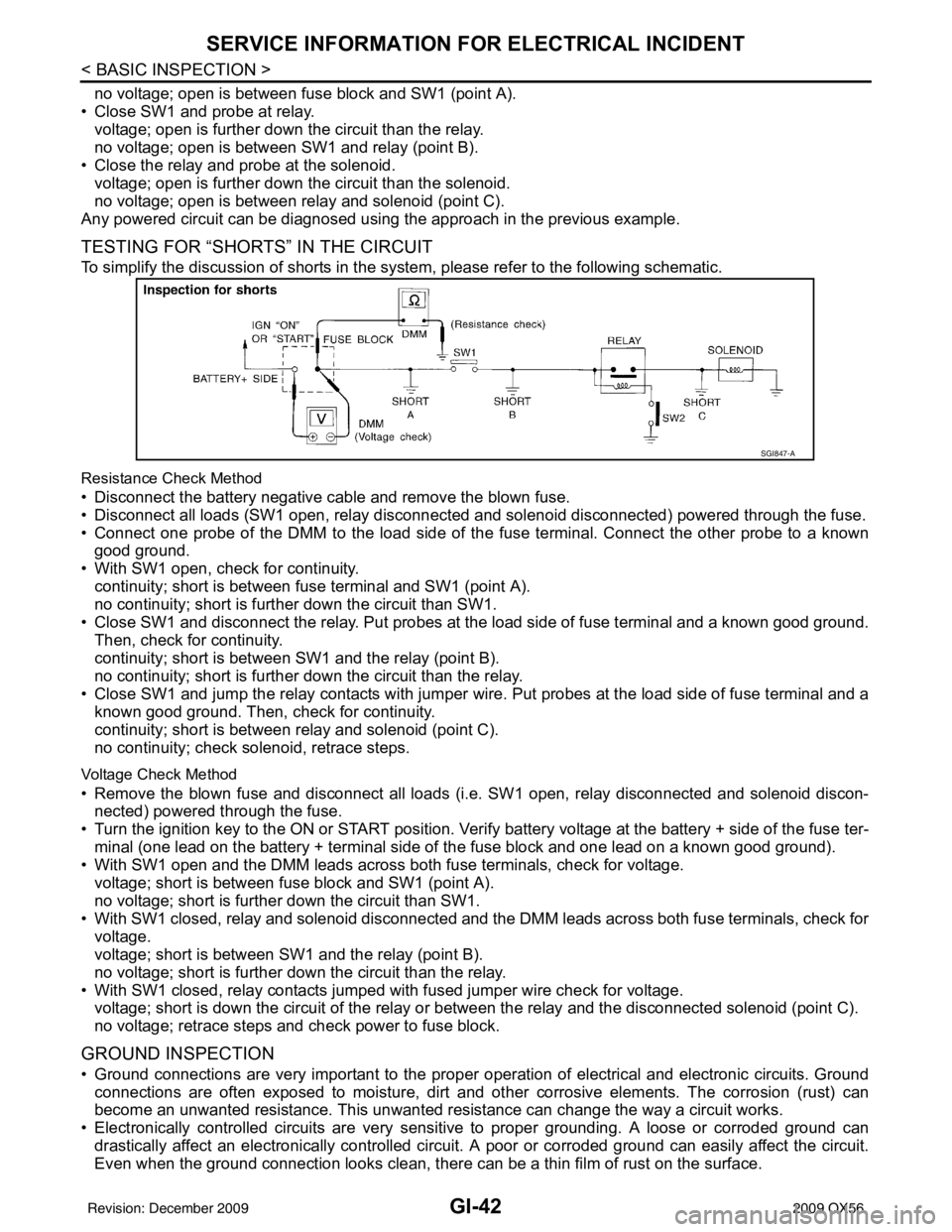
TESTING FOR “SHORTS” IN THE CIRCUIT
To simplify the discussion of shorts in the system, please refer to the following schematic.
Resistance Check Method
• Disconnect the battery negative cable and remove the blown fuse.
• Disconnect all loads (SW1 open, relay disconnected and solenoid disconnected) powered through the fuse.
• Connect one probe of the DMM to the load side of the fuse terminal. Connect the other probe to a known good ground.
• With SW1 open, check for continuity. continuity; short is between fuse terminal and SW1 (point A).
no continuity; short is further down the circuit than SW1.
• Close SW1 and disconnect the relay. Put probes at the load side of fuse terminal and a known good ground. Then, check for continuity.
continuity; short is between SW1 and the relay (point B).
no continuity; short is further down the circuit than the relay.
• Close SW1 and jump the relay contacts with jumper wire. Put probes at the load side of fuse terminal and a known good ground. Then, check for continuity.
continuity; short is between relay and solenoid (point C).
no continuity; check solenoid, retrace steps.
Voltage Check Method
• Remove the blown fuse and disconnect all loads (i.e. SW1 open, relay disconnected and solenoid discon-
nected) powered through the fuse.
• Turn the ignition key to the ON or START position. Verify battery voltage at the battery + side of the fuse ter- minal (one lead on the battery + terminal side of the fuse block and one lead on a known good ground).
• With SW1 open and the DMM leads across both fuse terminals, check for voltage. voltage; short is between fuse block and SW1 (point A).
no voltage; short is further down the circuit than SW1.
• With SW1 closed, relay and solenoid disconnected and the DMM leads across both fuse terminals, check for voltage.
voltage; short is between SW1 and the relay (point B).
no voltage; short is further down the circuit than the relay.
• With SW1 closed, relay contacts jumped with fused jumper wire check for voltage. voltage; short is down the circuit of the relay or between the relay and the disconnected solenoid (point C).
no voltage; retrace steps and check power to fuse block.
GROUND INSPECTION
• Ground connections are very important to the proper operation of electrical and electronic circuits. Ground
connections are often exposed to moisture, dirt and other corrosive elements. The corrosion (rust) can
become an unwanted resistance. This unwanted resistance can change the way a circuit works.
• Electronically controlled circuits are very sens itive to proper grounding. A loose or corroded ground can
drastically affect an electronically controlled circuit. A poor or corroded ground can easily affect the circuit.
Even when the ground connection looks clean, there c an be a thin film of rust on the surface.
SGI847-A
Revision: December 20092009 QX56
Page 2241 of 4171

CONSULT-III CHECKING SYSTEMGI-47
< BASIC INSPECTION >
C
DE
F
G H
I
J
K L
M B
GI
N
O P
x : Applicable
*1: With intelligent cruise control
*2: With 4-wheel drive
*3: With front and rear sonar system
CONSULT-III Data Link Connector (DLC) CircuitINFOID:0000000003771219
INSPECTION PROCEDURE
If the CONSULT-III cannot diagnose the sys tem properly, check the following items.
NOTE:
The CAN and DDL2 circuits from DLC pins 6, 7 and 14 may be connected to more than one system. A short in
any circuit connected to a control unit in one system may affect CONSULT-III access to other systems.
ECU discriminated
No.Classification number of a replacement ECU can
be read to prevent an incorrect ECU from being
installed.
----x--------------
Passenger Airbag Displays the STATUS (readiness) of the front
passenger air bag.
----x--------------
AV COMM monitor The condition of AV communication can be indi-
cated. ------------x------
Configuration Sets control module para
meters to match vehicle
options. ------x------------
Steering lock re-
lease The condition of steering lock release solenoid. -----------------x-
PIN read This mode shows the BCM-specific 5-digit code.-----------------x-
Control unit
initialization All registered ignition key IDs in NATS compo-
nents can be initialized and new IDs can be reg-
istered.
----------------x--
Diagnostic test
mode Function
ENGINE
TRANSMISSION
ICC
*1
ABS
AIR BAG
IPDM E/R BCM
METER/M&A
INTELLIGENT KEY
AUTO DRIVE POS.
REARVIEW CAMERA AIR LEVELIZER
MULTI AV
ALL MODE AWD/4WD
*2
HVAC
SONAR
*3
NVIS (NATS)
NVIS (NATS BCM OR S/ENT) NATS I-KEY
Symptom Check item
CONSULT-III cannot access
any system. • CONSULT-III DLC power supply circuit (Terminal 8) and ground circuit (Terminal 4)
CONSULT-III cannot access in-
dividual system. (Other sys-
tems can be accessed.) • Power supply and ground circuit for the control unit of the system (For detailed circuit, refer to wiring
diagram for each system.)
• Open or short circuit between the system and CONSULT-III DLC (For detailed circuit, refer to wiring diagram for each system.)
• Open or short circuit CAN communication line. Refer to LAN-14, "
Trouble Diagnosis Flow Chart".
Revision: December 20092009 QX56
Page 2244 of 4171
GW-2
< SYMPTOM DIAGNOSIS >
SQUEAK AND RATTLE TROUBLE DIAGNOSIS
SYMPTOM DIAGNOSIS
SQUEAK AND RATTLE TROUBLE DIAGNOSIS
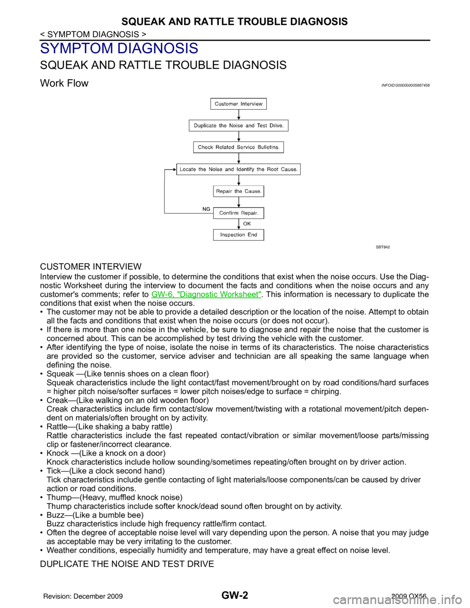
Work FlowINFOID:0000000005867456
CUSTOMER INTERVIEW
Interview the customer if possible, to determine the conditions that exist when the noise occurs. Use the Diag-
nostic Worksheet during the interview to document the facts and conditions when the noise occurs and any
customer's comments; refer to GW-6, "
Diagnostic Worksheet". This information is necessary to duplicate the
conditions that exist when the noise occurs.
• The customer may not be able to provide a detailed description or the location of the noise. Attempt to obtain
all the facts and conditions that exist w hen the noise occurs (or does not occur).
• If there is more than one noise in the vehicle, be sure to diagnose and repair the noise that the customer is
concerned about. This can be accomplished by test driving the vehicle with the customer.
• After identifying the type of noise, isolate the noise in terms of its characteristics. The noise characteristics
are provided so the customer, service adviser and technician are all speaking the same language when
defining the noise.
• Squeak —(Like tennis shoes on a clean floor) Squeak characteristics include the light contact/fast movement/brought on by road conditions/hard surfaces
= higher pitch noise/softer surfaces = lower pitch noises/edge to surface = chirping.
• Creak—(Like walking on an old wooden floor) Creak characteristics include firm contact/slow mo vement/twisting with a rotational movement/pitch depen-
dent on materials/often brought on by activity.
• Rattle—(Like shaking a baby rattle) Rattle characteristics include the fast repeated contac t/vibration or similar movement/loose parts/missing
clip or fastener/incorrect clearance.
• Knock —(Like a knock on a door) Knock characteristics include hollow sounding/someti mes repeating/often brought on by driver action.
• Tick—(Like a clock second hand) Tick characteristics include gentle contacting of light materials/loose components/can be caused by driver
action or road conditions.
• Thump—(Heavy, muffled knock noise)
Thump characteristics include softer k nock/dead sound often brought on by activity.
• Buzz—(Like a bumble bee) Buzz characteristics include hi gh frequency rattle/firm contact.
• Often the degree of acceptable noise level will vary depending upon the person. A noise that you may judge as acceptable may be very irritating to the customer.
• Weather conditions, especially humidity and temperat ure, may have a great effect on noise level.
DUPLICATE THE NOISE AND TEST DRIVE
SBT842
Revision: December 20092009 QX56
Page 2245 of 4171
SQUEAK AND RATTLE TROUBLE DIAGNOSISGW-3
< SYMPTOM DIAGNOSIS >
C
DE
F
G H
I
J
L
M A
B
GW
N
O P
If possible, drive the vehicle with the customer until the noise is duplicated. Note any additional information on
the Diagnostic Worksheet regarding the conditions or lo cation of the noise. This information can be used to
duplicate the same conditions when you confirm the repair.
If the noise can be duplicated easily during the test drive, to help identify the source of the noise, try to dupli-
cate the noise with the vehicle stopped by doing one or all of the following:
1) Close a door.
2) Tap or push/pull around the area where the noise appears to be coming from.
3) Rev the engine.
4) Use a floor jack to recreate vehicle “twist”.
5) At idle, apply engine load (electrical load, half- clutch on M/T model, drive position on A/T model).
6) Raise the vehicle on a hoist and hit a tire with a rubber hammer.
• Drive the vehicle and attempt to duplicate the conditions the customer states exist when the noise occurs.
• If it is difficult to duplicate the noise, drive the vehicle slowly on an undulating or rough road to stress the vehicle body.
CHECK RELATED SERVICE BULLETINS
After verifying the customer concern or symptom, check ASIST for Technical Service Bulletins (TSBs) related
to that concern or symptom.
If a TSB relates to the symptom, follow the procedure to repair the noise.
LOCATE THE NOISE AND IDENTIFY THE ROOT CAUSE
1. Narrow down the noise to a general area.To help pinpoint the source of the noise, use a listening tool (Chassis Ear: J-39570, Engine Ear: J-39565 and mechanic's stethoscope).
2. Narrow down the noise to a more specific area and identify the cause of the noise by:
• removing the components in the area that you suspect the noise is coming from. Do not use too much force when removing clips and fasteners, otherwise clips and fasteners can be broken
or lost during the repair, resulting in the creation of new noise.
• tapping or pushing/pulling the component that you suspect is causing the noise.
Do not tap or push/pull the component with excessive force, otherwise the noise will be eliminated only tem-
porarily.
• feeling for a vibration with your hand by touching the component(s) that you suspect is (are) causing the
noise.
• placing a piece of paper between components that you suspect are causing the noise.
• looking for loose components and contact marks. Refer to GW-4, "
Generic Squeak and Rattle Troubleshooting".
REPAIR THE CAUSE
• If the cause is a loose component, tighten the component securely.
• If the cause is insufficient clearance between components:
- separate components by repositioning or loos ening and retightening the component, if possible.
- insulate components with a suitable insulator such as urethane pads, foam blocks, felt cloth tape or urethane tape. A NISSAN Squeak and Rattle Kit (J-43980) is available through your authorized NISSAN Parts Depart-
ment.
CAUTION:
Do not use excessive force as many components are constructed of plastic and may be damaged.
Always check with the Parts Department for the latest parts information.
The following materials are contained in the NISSAN Squeak and Rattle Kit (J-43980). Each item can be
ordered separately as needed.
URETHANE PADS [1.5 mm (0.059 in) thick]
Insulates connectors, harness, etc.
76268-9E005: 100 ×135 mm (3.94 ×5.31 in)/76884-71L01: 60 ×85 mm (2.36× 3.35 in)/76884-71L02: 15× 25
mm (0.59 ×0.98 in)
INSULATOR (Foam blocks)
Insulates components from contact. Can be used to fill space behind a panel.
73982-9E000: 45 mm (1.77 in) thick, 50× 50 mm (1.97×1.97 in)/73982-50Y00: 10 mm (0.39 in) thick,
50× 50 mm (1.97 ×1.97 in)
INSULATOR (Light foam block)
80845-71L00: 30 mm (1.18 in) thick, 30 ×50 mm (1.18 ×1.97 in)
FELT CLOTH TAPE
Used to insulate where movement does not occu r. Ideal for instrument panel applications.
Revision: December 20092009 QX56