INFINITI QX56 2009 Factory Service Manual
Manufacturer: INFINITI, Model Year: 2009, Model line: QX56, Model: INFINITI QX56 2009Pages: 4171, PDF Size: 84.65 MB
Page 761 of 4171

RADIATORCO-17
< ON-VEHICLE REPAIR >
C
DE
F
G H
I
J
K L
M A
CO
NP
O
11. Lift up and remove the radiator.
CAUTION:
Do not damage or scratch air conditioner condenser and
radiator core when removing.
INSTALLATION
Installation is in the reverse order of removal.
INSPECTION AFTER INSTALLATION
• Check for leaks of engine coolant. Refer to CO-10, "Inspection".
• Start and warm up the engine. Visually check for leaks of the engine coolant and A/T fluid.
PBIC1536E
Revision: December 20092009 QX56
Page 762 of 4171

CO-18
< ON-VEHICLE REPAIR >
ENGINE COOLING FAN
ENGINE COOLING FAN
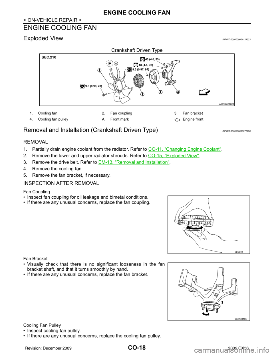
Exploded ViewINFOID:0000000004129533
Crankshaft Driven Type
Removal and Installation (Crankshaft Driven Type)INFOID:0000000003771288
REMOVAL
1. Partially drain engine coolant from the radiator. Refer to CO-11, "Changing Engine Coolant".
2. Remove the lower and upper radiator shrouds. Refer to CO-15, "
Exploded View".
3. Remove the drive belt. Refer to EM-13, "
Removal and Installation".
4. Remove the cooling fan.
5. Remove the fan bracket, if necessary.
INSPECTION AFTER REMOVAL
Fan Coupling
• Inspect fan coupling for oil leakage and bimetal conditions.
• If there are any unusual concerns, replace the fan coupling.
Fan Bracket
• Visually check that there is no significant looseness in the fan bracket shaft, and that it turns smoothly by hand.
• If there are any unusual concerns, replace the fan bracket.
Cooling Fan Pulley
• Inspect cooling fan pulley.
• If there are any unusual concerns, replace the cooling fan pulley.
AWBIA0812GB
1. Cooling fan 2. Fan coupling3. Fan bracket
4. Cooling fan pulley A. Front mark Engine front
SLC072
WBIA0418E
Revision: December 20092009 QX56
Page 763 of 4171

ENGINE COOLING FANCO-19
< ON-VEHICLE REPAIR >
C
DE
F
G H
I
J
K L
M A
CO
NP
O
INSTALLATION
Installation is in the reverse order of removal.
• Install cooling fan with its front mark “F” facing front of engine.
INSPECTION AFTER INSTALLATION
• Check for leaks of the engine coolant. Refer to
CO-10, "Inspection".
• Start and warm up the engine. Visually make sure that there are no leaks of the engine coolant.
Removal and Installati on (Motor Driven Type)INFOID:0000000003771289
REMOVAL
1. Remove the front bumper fascia. Refer to EXT-13, "Removal and Installation".
2. Disconnect the secondary hood release cable.
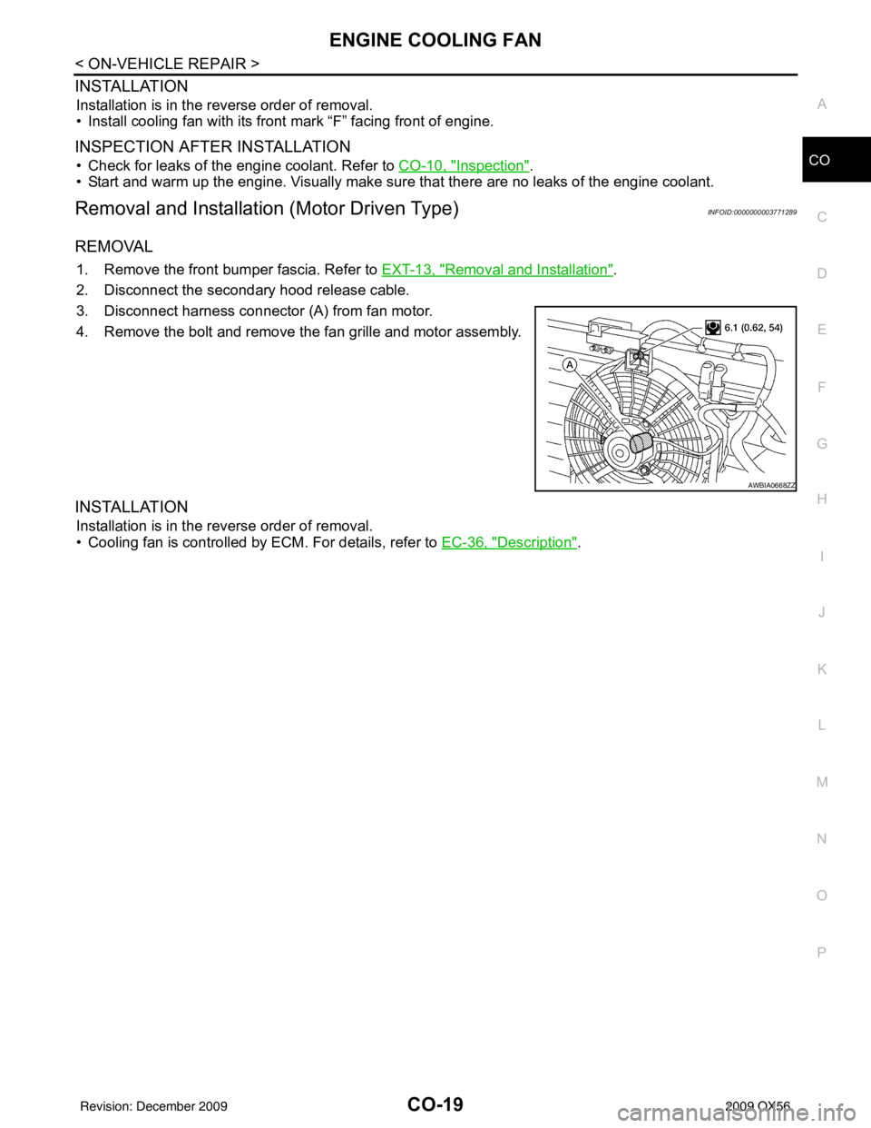
3. Disconnect harness connector (A) from fan motor.
4. Remove the bolt and remove the fan grille and motor assembly.
INSTALLATION
Installation is in the reverse order of removal.
• Cooling fan is controlled by ECM. For details, refer to EC-36, "
Description".
AWBIA0668ZZ
Revision: December 20092009 QX56
Page 764 of 4171

CO-20
< ON-VEHICLE REPAIR >
WATER PUMP
WATER PUMP
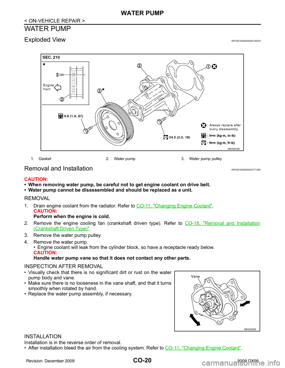
Exploded ViewINFOID:0000000004129534
Removal and InstallationINFOID:0000000003771290
CAUTION:
• When removing water pump, be careful not to get engine coolant on drive belt.
• Water pump cannot be disassembled and should be replaced as a unit.
REMOVAL
1. Drain engine coolant from the radiator. Refer to CO-11, "Changing Engine Coolant".
CAUTION:
Perform when the engine is cold.
2. Remove the engine cooling fan (crankshaft driven type). Refer to CO-18, "
Removal and Installation
(Crankshaft Driven Type)".
3. Remove the water pump pulley.
4. Remove the water pump. • Engine coolant will leak from the cylinder block, so have a receptacle ready below.
CAUTION:
Handle water pump vane so that it does not contact any other parts.
INSPECTION AFTER REMOVAL
• Visually check that there is no signi ficant dirt or rust on the water
pump body and vane.
• Make sure there is no looseness in the vane shaft, and that it turns smoothly when rotated by hand.
• Replace the water pump assembly, if necessary.
INSTALLATION
Installation is in the reverse order of removal.
• After installation bleed the air from the cooling system. Refer to CO-11, "
Changing Engine Coolant".
1. Gasket2. Water pump3. Water pump pulley
KBIA2543E
KBIA2552E
Revision: December 20092009 QX56
Page 765 of 4171

WATER PUMPCO-21
< ON-VEHICLE REPAIR >
C
DE
F
G H
I
J
K L
M A
CO
NP
O
INSPECTION AFTER INSTALLATION
• Check for leaks of engine coolant. Refer to
CO-10, "Inspection".
• Start and warm up engine. Visually c heck for leaks of the engine coolant.
Revision: December 20092009 QX56
Page 766 of 4171

CO-22
< ON-VEHICLE REPAIR >
THERMOSTAT AND WATER PIPING
THERMOSTAT AND WATER PIPING
Exploded ViewINFOID:0000000004129535
Removal and InstallationINFOID:0000000003771291
REMOVAL
Removal of Thermostat
1. Partially drain engine coolant from the radiator. Refer to CO-11, "Changing Engine Coolant".
CAUTION:
Perform when engine is cold.
2. Remove the air duct and resonator assembly. Refer to EM-25, "
Exploded View".
3. Disconnect the water suction hose from the water inlet.
4. Remove the water inlet and thermostat.
Removal of Thermostat Housing, Water Outlet and Heater Pipe
1. Remove the intake manifold. Refer to EM-26, "Removal and Installation".
2. Remove the thermostat housing, water outlet and heater pipe.
Removal of Water Cut Valve
1. Partially drain the engine coolant from the radiator. Refer to CO-11, "Changing Engine Coolant".
1. Heater pipe2. Gasket 3. Water outlet
4. Gasket 5. O-ring 6. O-ring
7. Thermostat housing 8. Rubber ring 9. Thermostat
10. Water inlet 11. Water suction hose 12. Water suction pipe
13. Gasket 14. Heater pipe
KBIA2501E
Revision: December 20092009 QX56
Page 767 of 4171

THERMOSTAT AND WATER PIPINGCO-23
< ON-VEHICLE REPAIR >
C
DE
F
G H
I
J
K L
M A
CO
NP
O
CAUTION:
Perform when the engine is cold.
2. Disconnect the water cut valve connector.
3. Disconnect the water hoses from the water cut valve.
4. Remove the water cut valve.
INSPECTION AFTER REMOVAL
• Place a thread so that it is caught in the valve of the thermostat.
Immerse fully in a container filled with water. Heat while stirring.
• The valve opening temperature is the temperature at which the valve opens and falls from the thread.
• Continue heating. Check the full-open lift amount.
• After checking the full-open lift amount, lower the water tempera- ture and check the valve closing temperature.
Standard values:
INSTALLATION
Installation is in the reverse order of removal.
Installation of Thermostat
• Install the thermostat with the whole circumference of each flange
part fit securely inside the rubber ring as shown.
• Install the thermostat with the jiggle valve facing upwards.
Installation of Water Outlet Pipe and Heater Pipe
First apply a neutral detergent to the O- rings, then quickly insert the insertion parts of the water outlet pipe and
heater pipe into the installation holes.
INSPECTION AFTER INSTALLATION
• Check for leaks of the engine coolant. Refer to CO-10, "Inspection".
• Start and warm up the engine. Visually check for leaks of the engine coolant.
SLC252B
Thermostat
Valve opening temperature 80 - 84°C (176 - 183 ° F)
Full-open lift amount More than 10 mm/ 95°C (0.39 in/ 203° F)
Valve closing temperature 77°C (171 °F) or higher
KBIA2502E
Revision: December 20092009 QX56
Page 768 of 4171

CO-24
< SERVICE DATA AND SPECIFICATIONS (SDS)
SERVICE DATA AND SPECIFICATIONS (SDS)
SERVICE DATA AND SPECIFICATIONS (SDS)
SERVICE DATA AND SPECIFICATIONS (SDS)
Standard and LimitINFOID:0000000003771292
ENGINE COOLANT CAPACITY (APPROXIMATE)
Unit: (US qt, Imp qt)
THERMOSTAT
RADIATOR
Unit: kPa (kg/cm2, psi)
Engine coolant capacity with reservoir ("MAX" level)14.4 (15 1/4, 12 5/8)
Valve opening temperature80 - 84°C (176 - 183 °F)
Full-open lift amount More than 10 mm/95°C (0.39 in/203°F)
Valve closing temperature 77°C (171 °F) or higher
Reservoir cap relief pressure Standard 95 - 125 (0.97- 1.28, 14 - 18)
Leakage test pressure 137 (1.4, 20)
Revision: December 20092009 QX56
Page 769 of 4171

DEF-1
DRIVER CONTROLS
C
DE
F
G H
I
J
K
M
SECTION DEF
A
B
DEF
N
O P
CONTENTS
DEFOGGER
BASIC INSPECTION ....... .............................3
DIAGNOSIS AND REPAIR WORKFLOW ..... .....3
Repair Work Flow ................................................ ......3
FUNCTION DIAGNOSIS ...............................4
REAR WINDOW DEFOGGER SYSTEM ........ .....4
System Diagram .................................................. ......4
System Description ...................................................4
Component Parts Location ........................................5
Component Description .............................................5
DIAGNOSIS SYSTEM (BCM) .............................6
COMMON ITEM ..................................................... ......6
COMMON ITEM : CONSULT-III Function (BCM -
COMMON ITEM) .......................................................
6
REAR WINDOW DEFOGGER ............................... ......6
REAR WINDOW DEFOGGER : CONSULT-III
Function (BCM - REAR DEFOGGER) ......................
7
CAN COMMUNICATION .....................................8
System Description ............................................. ......8
COMPONENT DIAGNOSIS ..........................9
REAR WINDOW DEFOGGER SWITCH ........ .....9
Description .......................................................... ......9
Component Function Check ......................................9
Diagnosis Procedure .................................................9
REAR WINDOW DEFOGGER RELAY ..............10
Description .......................................................... ....10
Component Function Check ....................................10
Diagnosis Procedure ...............................................10
REAR WINDOW DEFOGGER POWER SUP-
PLY AND GROUND CIRCUIT ............................
11
Description .......................................................... ....11
Component Function Check ....................................11
Diagnosis Procedure ........................................... ....11
Component Inspection .............................................12
DOOR MIRROR DEFOGGER LH .....................13
Description ...............................................................13
Component Function Check ....................................13
Diagnosis Procedure ...............................................13
Component Inspection .............................................14
DOOR MIRROR DEFOGGER RH .....................15
Description ...............................................................15
Component Function Check ....................................15
Diagnosis Procedure ...............................................15
Component Inspection .............................................16
ECU DIAGNOSIS .........................................17
BCM (BODY CONTROL MODULE) .................17
Reference Value .................................................. ....17
Terminal Layout .......................................................19
Physical Values ................................................... ....19
Wiring Diagram ........................................................25
Fail Safe ..................................................................32
DTC Inspection Priority Chart ...............................33
DTC Index ...............................................................33
SYMPTOM DIAGNOSIS ..............................35
REAR WINDOW DEFOGGER AND DOOR
MIRROR DEFOGGER DO NOT OPERATE. ....
35
Diagnosis Procedure ........................................... ....35
REAR WINDOW DEFOGGER DOES NOT
OPERATE BUT BOTH OF DOOR MIRROR
DEFOGGER OPERATE. ...................................
36
Diagnosis Procedure ...............................................36
BOTH DOORS MIRROR DEFOGGER DON’T
OPERATE BUT REAR WINDOW DEFOG-
GER OPERATES ..............................................
37
Diagnosis Procedure ...............................................37
Revision: December 20092009 QX56
Page 770 of 4171

DEF-2
DRIVER SIDE DOOR MIRROR DEFOGGER
DOES NOT OPERATE. .....................................
38
Diagnosis Procedure ........................................... ...38
PASSENGER SIDE DOOR MIRROR DEFOG-
GER DOES NOT OPERATE. ............................
39
Diagnosis Procedure ........................................... ...39
REAR WINDOW DEFOGGER SWITCH DOES
NOT LIGHT, BUT REAR WINDOW DEFOG-
GER OPERATES ...............................................
40
Diagnosis Procedure ........................................... ...40
PRECAUTION .............................................41
PRECAUTIONS .............................................. ...41
Precaution for Supplemental Restraint System
(SRS) "AIR BAG" and "SEAT BELT PRE-TEN-
SIONER" .............................................................. ...
41
Handling for Adhesive and Primer ..........................41
Precaution Necessary for Steering Wheel Rota-
tion After Battery Disconnect ..................................
41
ON-VEHICLE REPAIR ...............................43
REAR WINDOW DEFOGGER ........................ ...43
Filament Check .................................................... ...43
Filament Repair .......................................................43
Revision: December 20092009 QX56