ECU INFINITI QX56 2009 Factory Service Manual
[x] Cancel search | Manufacturer: INFINITI, Model Year: 2009, Model line: QX56, Model: INFINITI QX56 2009Pages: 4171, PDF Size: 84.65 MB
Page 3490 of 4171

DIAGNOSIS SENSOR UNITSR-17
< ON-VEHICLE REPAIR >
C
DE
F
G
I
J
K L
M A
B
SR
N
O P
DIAGNOSIS SENSOR UNIT
Removal and InstallationINFOID:0000000003775164
REMOVAL
CAUTION:
• Before servicing the SRS, turn the ignition switch off, disconnect both battery cables and wait at least 3 minutes.
• Do not use old bolts; replace with new bolts.
• Check diagnosis sensor unit bracket to make sure it is free of deformities, dents, cracks or rust. If it
shows any visible signs of damage, replace with new one.
• Replace diagnosis sensor unit if it has been dropped or sustained an impact.
• When replacing the air bag diagno sis sensor unit, always check with the parts department for he lat-
est parts information. Installing an incorrect air bag diagnosis sensor unit may or may not cause the
air bag warning lamp to illuminate and may cause incorrect deployment of the supplemental air bags
and seat belt pre-tensioner in a collision r esulting in serious personal injury or death.
1. Always check the air bag diagnosis sensor unit E CU discriminated number (identification number) using
CONSULT-III.
2. Disconnect the negative and positive battery term inals, then wait at least three minutes.
3. Disconnect the harness connectors for each air bag module and seat belt pre-tensioner.
4. Remove center console. Refer to IP-20, "
Removal and Installation".
5. Disconnect diagnosis sensor unit harness connectors.
6. Remove bolts from the diagnosis sensor unit.
INSTALLATION
Installation is in the reverse order of removal.
• After the work is completed, perform self-diagnosis to check that no malfunction is detected. Refer to SRC-
13, "SRS Operation Check".
CAUTION:
• After replacing the air bag diagnosis sensor unit, confirm using CO NSULT-III that the ECU discrimi-
nated number (identification number) of the ne w replacement air bag diagnosis sensor unit matches
the ECU discriminated number (identification numb er) of the replaced (old) air bag diagnosis sensor
unit.
• The diagnosis sensor unit must always be installed with the arrow mark " ⇐" pointing toward the
front of the vehicle for proper operation.
NOTE:
1. Diagnosis sensor unit ⇐Vehicle front
AWHIA0159ZZ
Revision: December 20092009 QX56
Page 3491 of 4171

SR-18
< ON-VEHICLE REPAIR >
DIAGNOSIS SENSOR UNIT
If the ECU discriminated number of the new replacement air bag diagnosis sensor unit differs from the ECU
discriminated number of the replaced air bag diagnosis sensor unit, reconfirm the parts information and verify
that the correct air bag diagnosis sensor unit was installed.
Revision: December 20092009 QX56
Page 3500 of 4171

SRC-2
Diagnosis Procedure (Component Diagnosis) ........39
B1086 – B1089 SEAT BELT PRE-TENSION-
ER LH .................................................................
41
Description ........................................................... ...41
DTC Logic ...............................................................41
Diagnosis Procedure (Component Diagnosis) ........42
B1081 – B1084 SEAT BELT PRE-TENSION-
ER RH ................................................................
44
Description ..............................................................44
DTC Logic ...............................................................44
Diagnosis Procedure (Component Diagnosis) ........45
B1182 - B1185 SEAT BELT BUCKLE PRE-
TENSIONER LH .................................................
47
Description ........................................................... ...47
DTC Logic ...............................................................47
Diagnosis Procedure (Component Diagnosis) ........48
B1177 - B1180 SEAT BELT BUCKLE PRE-
TENSIONER RH ................................................
50
Description ........................................................... ...50
DTC Logic ...............................................................50
Diagnosis Procedure (Component Diagnosis) ........51
B1033 – B1035 CRASH ZONE SENSOR .........53
Description ........................................................... ...53
DTC Logic ...............................................................53
Diagnosis Procedure (Component Diagnosis) ........54
B1118 – B1120 SATELLITE SENSOR LH ........56
Description ........................................................... ...56
DTC Logic ...............................................................56
Diagnosis Procedure (Component Diagnosis) ........57
B1113 – B1115 SATELLITE SENSOR RH .......59
Description ........................................................... ...59
DTC Logic ...............................................................59
Diagnosis Procedure (Component Diagnosis) ........60
B1XXX AIR BAG DIAGNOSIS SENSOR UNIT ...62
Description ........................................................... ...62
DTC Logic ...............................................................62
Diagnosis Procedure (Component Diagnosis) ........63
B1023 PASSENGER AIR BAG OFF INDICA-
TOR ....................................................................
64
Description ........................................................... ...64
DTC Logic ...............................................................64
Diagnosis Procedure (Component Diagnosis) ........65
B1017 – B1022 OCCUPANT CLASSIFICA-
TION SYSTEM ................................................ ...
67
Description ........................................................... ...67
DTC Logic ...............................................................67
Diagnosis Procedure (Component Diagnosis) ........68
B1209 – B1211 COLLISION DETECTION ........71
Description ........................................................... ...71
DTC Logic ...............................................................71
Diagnosis Procedure (Component Diagnosis) ........71
ECU DIAGNOSIS .......................................72
DIAGNOSIS SENSOR UNIT .............................72
Wiring Diagram .................................................... ...72
Trouble Diagnosis with CONSULT-III .....................81
Trouble Diagnosis without CONSULT-III ................85
SYMPTOM DIAGNOSIS ............................90
SRS AIR BAG SYSTEM ................................. ...90
"AIR BAG" Warning Lamp Does Not Turn Off ..... ...90
"AIR BAG" Warning Lamp Does Not Turn On ........90
PASSENGER SEAT BELT WARNING SYS-
TEM ....................................................................
92
Seat Belt Warning System Does Not Function .... ...92
PRECAUTION ............................................93
PRECAUTIONS .............................................. ...93
Precaution for Supplemental Restraint System
(SRS) "AIR BAG" and "SEAT BELT PRE-TEN-
SIONER" .............................................................. ...
93
Precaution for SRS "AIR BAG" and "SEAT BELT
PRE-TENSIONER" Service ................................. ...
93
Occupant Classification System Precaution ...........93
Revision: December 20092009 QX56
Page 3506 of 4171

SRC-8
< FUNCTION DIAGNOSIS >
SRS AIR BAG SYSTEM
Front Passenger Air Bag Module
INFOID:0000000003775174
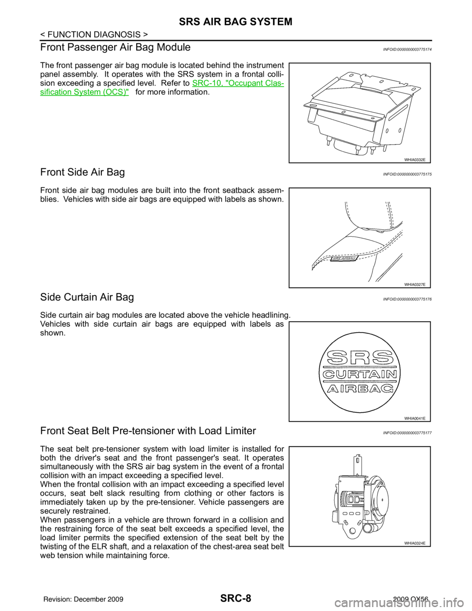
The front passenger air bag module is located behind the instrument
panel assembly. It operates with the SRS system in a frontal colli-
sion exceeding a specified level. Refer to SRC-10, "
Occupant Clas-
sification System (OCS)" for more information.
Front Side Air BagINFOID:0000000003775175
Front side air bag modules are built into the front seatback assem-
blies. Vehicles with side air bags are equipped with labels as shown.
Side Curtain Air BagINFOID:0000000003775176
Side curtain air bag modules are located above the vehicle headlining.
Vehicles with side curtain air bags are equipped with labels as
shown.
Front Seat Belt Pre-te nsioner with Load LimiterINFOID:0000000003775177
The seat belt pre-tensioner system wi th load limiter is installed for
both the driver's seat and the front passenger's seat. It operates
simultaneously with the SRS air bag system in the event of a frontal
collision with an impact exceeding a specified level.
When the frontal collision with an im pact exceeding a specified level
occurs, seat belt slack resulting from clothing or other factors is
immediately taken up by the pre-tensioner. Vehicle passengers are
securely restrained.
When passengers in a vehicle are thrown forward in a collision and
the restraining force of the seat belt exceeds a specified level, the
load limiter permits the specified extension of the seat belt by the
twisting of the ELR shaft, and a relaxation of the chest-area seat belt
web tension while maintaining force.
WHIA0332E
WHIA0327E
WHIA0041E
WHIA0324E
Revision: December 20092009 QX56
Page 3513 of 4171

ON BOARD DIAGNOSTIC (OBD) SYSTEMSRC-15
< FUNCTION DIAGNOSIS >
C
DE
F
G
I
J
K L
M A
B
SRC
N
O P
Trouble Diagnosis without CONSULT-IIIINFOID:0000000003775186
DIAGNOSTIC PROCEDURE 6
Inspect SRS Malfunction Using "AIR BAG" Warning Lamp—Diagnosis Mode
NOTE:
SRS will not enter Diagnosis mode if no malfunction is detected in User mode.
1. Turn ignition switch ON.
2. After “AIR BAG” warning lamp lights for 7 seconds, turn ignition switch OFF within 1 second.
3. Wait more than 3 seconds.
4. Repeat steps 1 to 3 two more times (3 times total).
5. Turn ignition switch ON.
SRS is now in Diagnosis mode. Refer to SRC-85, "
Trouble Diagnosis without CONSULT-III".
CONSULT-III Function (AIR BAG)INFOID:0000000003775187
CONSULT-III can display each diagnostic item using the diagnostic test modes shown following.
Self-Diagnosis Function (Without CONSULT-III)INFOID:0000000003775188
• The reading of these results is accomplished using one of two modes — “User mode” and “Diagnosis
mode”.
• After a malfunction is repaired, turn the ignition s witch OFF for at least one second, then back ON. Diagnosis
mode returns to the User mode. At that time, the self-diagnostic result is cleared.
AIR BAG diagnostic mode Description
SELF-DIAG [CURRENT] A current Self-diagnosis result (also indicated by the number of warning lamp flashes in the Diagnosis
mode) is displayed on the CONSULT-III screen in real
time. This refers to a malfunctioning part requir-
ing repairs.
SELF-DIAG [PAST] Diagnosis results previously stored in the memo
ry are displayed on the CONSULT-III screen. The
stored results will remain until memory erasing is executed.
TROUBLE DIAG RECORD With TROUBLE DIAG RECORD, diagnosis results previously erased by a reset operation can be dis-
played on the CONSULT-III screen.
ECU DISCRIMINATED NO. Air bag diagnosis sensor unit ECU discriminated number (identification number) is displayed. Air bag
diagnosis sensor unit has individual ECU discriminated number (identification number) based on model
and equipment.
PASSENGER AIR BAG The STATUS (readiness) of the front passenger air bag module is displayed. The STATUS displayed
(ON/OFF) depends on the signals supplied to the occupant classification system control module and
air bag diagnosis sensor unit. Refer to
SRC-10, "
Occupant Classification System (OCS)" for more in-
formation.
Revision: December 20092009 QX56
Page 3570 of 4171

SRC-72
< ECU DIAGNOSIS >
DIAGNOSIS SENSOR UNIT
ECU DIAGNOSIS
DIAGNOSIS SENSOR UNIT
Wiring DiagramINFOID:0000000003775246
ABHWA0004GB
Revision: December 20092009 QX56
Page 3571 of 4171

DIAGNOSIS SENSOR UNITSRC-73
< ECU DIAGNOSIS >
C
DE
F
G
I
J
K L
M A
B
SRC
N
O P
ABHWA0005GB
Revision: December 20092009 QX56
Page 3572 of 4171

SRC-74
< ECU DIAGNOSIS >
DIAGNOSIS SENSOR UNIT
ABHIA0010GB
Revision: December 20092009 QX56
Page 3573 of 4171

DIAGNOSIS SENSOR UNITSRC-75
< ECU DIAGNOSIS >
C
DE
F
G
I
J
K L
M A
B
SRC
N
O P
ABHIA0011GB
Revision: December 20092009 QX56
Page 3574 of 4171

SRC-76
< ECU DIAGNOSIS >
DIAGNOSIS SENSOR UNIT
ABHIA0012GB
Revision: December 20092009 QX56