dimensions INFINITI QX56 2009 Factory Service Manual
[x] Cancel search | Manufacturer: INFINITI, Model Year: 2009, Model line: QX56, Model: INFINITI QX56 2009Pages: 4171, PDF Size: 84.65 MB
Page 200 of 4171
![INFINITI QX56 2009 Factory Service Manual AV-14
< FUNCTION DIAGNOSIS >[AUDIO SYSTEM]
NAVIGATION SYSTEM
MAP–MATCHING
Map–matching is a function that repositions the vehicle on the road
map when a new location is judged to be the most accur INFINITI QX56 2009 Factory Service Manual AV-14
< FUNCTION DIAGNOSIS >[AUDIO SYSTEM]
NAVIGATION SYSTEM
MAP–MATCHING
Map–matching is a function that repositions the vehicle on the road
map when a new location is judged to be the most accur](/img/42/57031/w960_57031-199.png)
AV-14
< FUNCTION DIAGNOSIS >[AUDIO SYSTEM]
NAVIGATION SYSTEM
MAP–MATCHING
Map–matching is a function that repositions the vehicle on the road
map when a new location is judged to be the most accurate. This is
done by comparing the current vehicle position, calculated by the
method described in the position detection principle, with the road
map data around the vehicle, read from the map data stored on the
HDD.
Therefore, the vehicle position may not be corrected after the vehicle
is driven over a certain distance or time in which GPS information is
hard to receive. In this case, the current-location mark on the display
must be corrected manually.
CAUTION:
The road map data is based on data stored on the HDD.
• In map-matching, alternative rout
es to reach the destination will be
shown and prioritized, after the road on which the vehicle is cur-
rently driven has been judged and the current-location mark has
been repositioned.
If there is an error in distance and/or direction, the alternative
routes will be shown in different order of priority, and the wrong
road can be avoided.
If two roads are running in parallel, they are of the same priority.
Therefore, the current-location mark may appear on either of them
alternately, depending on maneuvering of the steering wheel and
configuration of the road.
• Map-matching does not function correctly when the road on which the vehicle is driving is new and not recorded on the HDD, or when
the road pattern stored in the m ap data and the actual road pattern
are different due to repair.
When driving on a road not present in the map, the map-matching
function may find another road and position the current-location
mark on it. Then, when the correct road is detected, the current-
location mark may leap to it.
• Effective range for comparing the vehicle position and travel direc-
tion calculated by the distance and direction with the road data
read from the HDD is limited. Therefore, when there is an exces-
sive gap between the current vehicle position and the position on
the map, correction by map-matching is not possible.
GPS (GLOBAL POSITIONING SYSTEM)
GPS (Global Positioning System) has been developed and con-
trolled by the US Department of Defense. The system utilizes GPS
satellite (NAVSTAR), sending out radio waves while flying on an orbit
around the earth at the height of approx. 21,000 km (13,000 miles).
The GPS receiver calculates the vehicle's position in three dimen-
sions (latitude/longitude/altitude) according to the time lag of the
radio waves received from four or more GPS satellites (three-dimen-
sional positioning). If radio waves were received only from three
GPS satellites, the GPS receiver calculates the vehicle's position in
two dimensions (latitude/longitude), utilizing the altitude data calcu-
lated previously by using radio wa ves from four or more GPS satel-
lites (two-dimensional positioning).
Type Advantage Disadvantage
Gyroscope (angular velocity sensor) • Can detect the vehicle's turning angle quite
accurately. • Direction errors may accumulate when the ve-
hicle is driven for long distances without stop-
ping.
GPS antenna (GPS information) • Can detect the vehicle's travel direction
(North/South/East/West). • Correct direction cannot be detected when the
vehicle speed is low.
SEL685V
SEL686V
ALNIA0839GB
SEL526V
Revision: December 20092009 QX56
Page 618 of 4171

BRM-22
< SERVICE INFORMATION >
BODY REPAIR
A mark has been placed on each body panel to indicate the parts matching positions. When repairing parts
damaged by an accident which might affect the vehicle st ructure (members, pillars, etc.), more accurate and
effective repair will be possible by using these marks together with body alignment specifications.
DESCRIPTION
• All dimensions indicated in the figures are actual.
• When using a tracking gauge, adjust both pointers to equal length. Then check the pointers and gauge itself
to make sure there is no free play.
• When a measuring tape is used, check to be sure there is no elongation, twisting or bending.
• Measurements should be taken at the center of the mounting holes.
• An asterisk (*) following the value at the measuring point indicates that the measuring point on the other side
is symmetrically the same value.
• The coordinates of the measurement points are the di stances measured from the standard line of "X", "Y"
and "Z".
WIIA0284E
Revision: December 20092009 QX56
Page 747 of 4171

PRECAUTIONSCO-3
< PRECAUTION >
C
DE
F
G H
I
J
K L
M A
CO
NP
O
5. When the repair work is completed, return the ignition switch to the
″LOCK ″ position before connecting
the battery cables. (At this time, the steering lock mechanism will engage.)
6. Perform a self-diagnosis check of al l control units using CONSULT-III.
Precaution for Liquid GasketINFOID:0000000003771278
REMOVAL OF LIQUID GASKET SEALING
• After removing the bolts and nuts, separate the mating surface and
remove the old liquid gasket sealing using Tool.
CAUTION:
Do not damage the mating surfaces.
• Tap the seal cutter to insert it (1).
• In areas where the Tool is difficult to use, lightly tap to slide it (2).
LIQUID GASKET APPLICATION PROCEDURE
1. Remove the old liquid gasket adhering to the gasket application surface and the mating surface using suitable tool.
• Remove the liquid gasket completely from the groove of the
liquid gasket application surface, bolts, and bolt holes.
2. Thoroughly clean the mating surfaces and remove adhering moisture, grease and foreign material.
3. Attach the liquid gasket tube to the Tool. Use Genuine RTV Silicone Sealant or equivalent. Refer to
GI-15, "
Recommended Chemical Products and Sealants".
4. Apply the liquid gasket without breaks to the specified location with the specified dimensions.
• If there is a groove for the liquid gasket application, apply theliquid gasket to the groove.
• As for the bolt holes, normally apply the liquid gasket inside
the holes. If specified in the procedure, it should also be
applied outside the holes.
• Within five minutes of liquid gasket application, install the mat-
ing component.
• If the liquid gasket protrudes, wipe it off immediately.
• Do not retighten after the installation.
• Wait 30 minutes or more after installation before refilling the engine with engine oil and engine coolant.
CAUTION:
If there are specific instructions in this manual, observe them.
Tool number : KV10111100 (J-37228)
WBIA0566E
PBIC0003E
Tool number : WS39930000 ( — )
WBIA0567E
SEM159F
Revision: December 20092009 QX56
Page 1831 of 4171

EM-8
< PREPARATION >
PREPARATION
Commercial Service Tool
INFOID:0000000005885858
(Kent-Moore No.)
Tool name Description
Power tool Loosening bolts and nuts
Spark plug wrench Removing and installing spark plug
(J-24239-01)
Cylinder head bolt wrench Loosening and tightening cylinder head bolt,
and use with angle wrench [SST: KV10112100
(BT-8653-A)]
a: 13 (0.51) dia.
b: 12 (0.47)
c: 10 (0.39)
Unit: mm (in)
Valve seat cutter set Finishing valve seat dimensions
Pulley puller Removing crankshaft pulley
Piston ring expander Removing and installing piston ring
PBIC0190E
S-NT047
NT583
S-NT048
ZZA0010D
S-NT030
Revision: December 20092009 QX56
Page 1896 of 4171

CYLINDER HEADEM-73
< ON-VEHICLE REPAIR >
C
DE
F
G H
I
J
K L
M A
EM
NP
O
2. Measure the bottom surface of the cylinder head for distortion in
six directions as shown, using suitable tools.
• If measurement exceeds the limit, replace the cylinder head.
VALVE DIMENSIONS
• Check the dimensions of each valve. Refer to EM-108, "Standard
and Limit".
• If the dimensions are out of the standard, replace the valve.
VALVE GUIDE CLEARANCE
Valve Stem Diameter
Measure the diameter of the va lve stem using suitable tool.
Valve Guide Inside Diameter
Measure the inside diameter of the valve guide using suitable tool.
Valve Guide Clearance
• (Valve guide clearance) = (Valve guide inside diameter) – (Valve stem diameter).
• If the calculated value exceeds the limit, replace valve and/or valve guide. When the valve guide must be
replaced, follow the valve guide replacement procedure. Standard : 0.03 mm (0.0012 in)
Limit : 0.1 mm (0.004 in)
PBIC0075E
SEM188A
Standard
Intake : 5.965 - 5.980 mm (0.2348 - 0.2354 in)
Exhaust : 5.955 - 5.970 mm (0.2344 - 0.2350 in)
SEM938C
StandardIntake and Exhaust : 6.000 - 6.018 mm (0.2362 - 0.2369 in)
Valve guide clearance:
Standard Intake : 0.020 - 0.053 mm (0.0008 - 0.0021 in)
Exhaust : 0.030 - 0.063 mm (0.0012 - 0.0025 in)
Limit Intake : 0.08 mm (0.0031 in)
Exhaust : 0.09 mm (0.0035 in)
Revision: December 20092009 QX56
Page 1898 of 4171

CYLINDER HEADEM-75
< ON-VEHICLE REPAIR >
C
DE
F
G H
I
J
K L
M A
EM
NP
O
5. Press the valve guide from the camshaft side to the dimensions
as shown.
CAUTION:
Cylinder head contains heat . When working, wear protec-
tive equipment to avo id getting burned.
6. Ream the cylinder head valve guide using suitable tool.
VALVE SEAT CONTACT
• After confirming that the dimensions of the valve guides and valves are within specifications, perform this procedure.
• Apply prussian blue (or white lead) onto the contacting surface of the valve seat to check the condition of the valve contact on the
surface.
• Check if the contact area band is continuous all around the circum- ference.
• If not, grind to adjust the valve fi t and check again. If the contacting
surface still has NG conditions even after the re-check, replace the
valve seat.
VALVE SEAT REPLACEMENT
When the valve seat is removed, replace it with oversized (0.5 mm, 0.020 in) valve seat.
1. Bore out the old seat until it collapses. Boring should not continue beyond the bottom face of the seat recess in the cylinder head. Set the machine depth stop to ensure this.
2. Ream the cylinder head recess diameter for service valve seat.
• Be sure to ream in circles concentric to the valve guide center.
• This will enable valve seat to fit correctly.
KBIA2530E
Valve guide inside diameter:
Intake and exhaust : 6.000 - 6.018 mm (0.2362 - 0.2369 in)
SEM932C
SBIA0322E
Oversize [0.5 mm (0.020 in)] (Service):
Intake : 38.500 - 38.516 mm (1.5157 - 1.5164 in)
Exhaust : 32.700 - 32.716 mm (1.2874 - 1.2880 in)
SEM795A
Revision: December 20092009 QX56
Page 1899 of 4171

EM-76
< ON-VEHICLE REPAIR >
CYLINDER HEAD
3. Heat the cylinder head to 110° to 130° C (230° to 266° F) by
soaking it in heated oil.
4. Cool the valve seats well with dry ice. Force fit the valve seat into the cylinder head. CAUTION:
• Avoid directly touching cold valve seats.
• Cylinder head contains heat. When working, wear protective eq uipment to avoid getting burned.
5. Finish the seat to the specified dimensions using suitable tool. Refer to EM-108, "
Standard and Limit".
CAUTION:
When using valve seat cutter, firmly grip the cutter handle
with both hands. Then, pr ess on the contacting surface all
around the circumference to cu t in a single drive. Improper
pressure on the cutter or cutting many different times may
result in stage valve seat.
6. Grind to obtain the dimensions indicated as shown. • Using compound, grind to adjust valve fitting.
7. Check again for normal contact.
VALVE SPRING SQUARENESS
SEM008A
SEM934C
KBIA2531E
KBIA2544E
Revision: December 20092009 QX56
Page 1900 of 4171

CYLINDER HEADEM-77
< ON-VEHICLE REPAIR >
C
DE
F
G H
I
J
K L
M A
EM
NP
O
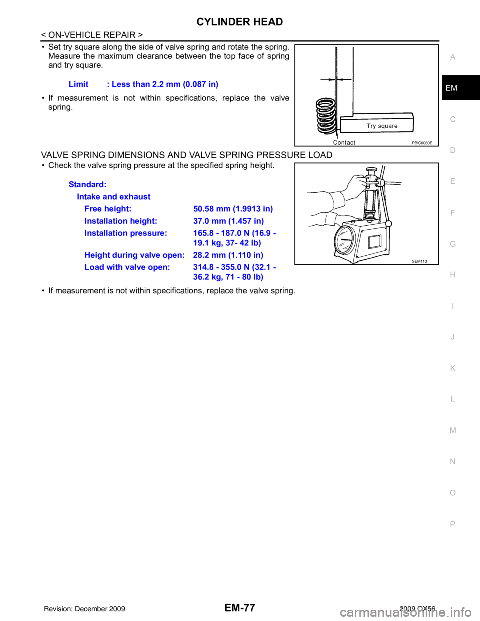
• Set try square along the side of valve spring and rotate the spring.
Measure the maximum clearance between the top face of spring
and try square.
• If measurement is not within specifications, replace the valve spring.
VALVE SPRING DIMENSIONS AND VALVE SPRING PRESSURE LOAD
• Check the valve spring pressure at the specified spring height.
• If measurement is not within specifications, replace the valve spring. Limit : Less than 2.2 mm (0.087 in)
PBIC0080E
Standard:
Intake and exhaustFree height: 50.58 mm (1.9913 in)
Installation height: 37.0 mm (1.457 in)
Installation pressure: 165.8 - 187.0 N (16.9 - 19.1 kg, 37- 42 lb)
Height during valve open: 28.2 mm (1.110 in)
Load with valve open: 314.8 - 355.0 N (32.1 - 36.2 kg, 71 - 80 lb)
SEM113
Revision: December 20092009 QX56
Page 1920 of 4171

ENGINE UNITEM-97
< DISASSEMBLY AND ASSEMBLY >
C
DE
F
G H
I
J
K L
M A
EM
NP
O
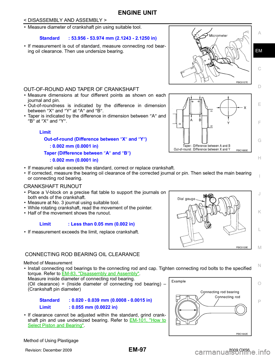
• Measure diameter of crankshaft pin using suitable tool.
• If measurement is out of standard, measure connecting rod bear-
ing oil clearance. Then use undersize bearing.
OUT-OF-ROUND AND TAPER OF CRANKSHAFT
• Measure dimensions at four di fferent points as shown on each
journal and pin.
• Out-of-roundness is indicated by the difference in dimension
between ″X″ and ″Y″ at ″A″ and ″B″ .
• Taper is indicated by the difference in dimension between ″A ″ and
″ B″ at ″X ″ and ″Y″ .
• If measured value exceeds the standard, correct or replace crankshaft.
• If corrected, measure the bearing oil clearance of the corrected journal or pin. Then select the main bearing or connecting rod bearing.
CRANKSHAFT RUNOUT
• Place a V-block on a precise flat table to support the journals onboth ends of the crankshaft.
• Measure at No. 3 journal using suitable tool.
• While rotating crankshaft, read the movement of the pointer.
• Half of the movement shows the runout.
• If measurement exceeds the limit, replace crankshaft.
CONNECTING ROD BEARING OIL CLEARANCE
Method of Measurement
• Install connecting rod bearings to the connecting rod and cap. Tighten connecting rod bolts to the specified
torque. Refer to EM-83, "
Disassembly and Assembly".
Measure inside diameter of connecting rod bearing.
(Oil clearance) = (Inside diameter of connecting rod bearing) –
(Crankshaft pin diameter)
• If clearance cannot be adjusted wit hin the standard, grind crank-
shaft pin and use undersized bearing. Refer to EM-101, "
How to
Select Piston and Bearing".
Method of Using Plastigage
Standard : 53.956 - 53.974 mm (2.1243 - 2.1250 in)
PBIC0127E
Limit
Out-of-round (Difference between ″X ″ and ″ Y″)
: 0.002 mm (0.0001 in)
Taper (Difference between ″ A″ and ″B ″)
: 0.002 mm (0.0001 in)
PBIC1685E
Limit : Less than 0.05 mm (0.002 in)
PBIC0129E
Standard : 0.020 - 0.039 mm (0.0008 - 0.0015 in)
Limit : 0.055 mm (0.0022 in)
PBIC1642E
Revision: December 20092009 QX56
Page 1925 of 4171

EM-102
< DISASSEMBLY AND ASSEMBLY >
HOW TO SELECT PISTON AND BEARING
When Cylinder Block is Reused
1. Measure cylinder block bore diameter.
2. Determine the bore grade by comparing the measurement with the values under the “Cylinder bore diam-
eter” of the piston selection table.
Piston Selection Table
Unit: mm (in)
NOTE:
• The piston is available together with piston pin as an assembly.
• The piston pin (piston pin bore) grade is provided only for the parts installed at the plant. For service parts, no grades can be selected (only 0 grade is available).
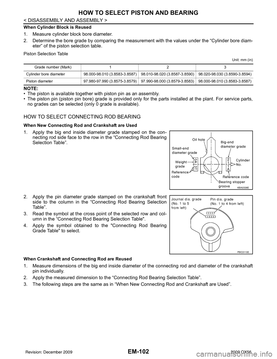
HOW TO SELECT CONNECTING ROD BEARING
When New Connecting Rod and Crankshaft are Used
1. Apply the big end inside diameter grade stamped on the con-
necting rod side face to the row in the “Connecting Rod Bearing
Selection Table”.
2. Apply the pin diameter grade stamped on the crankshaft front side to the column in the “Connecting Rod Bearing Selection
Table”.
3. Read the symbol at the cross point of the selected row and col-
umn in the “Connecting Rod Bearing Selection Table".
4. Apply the symbol obtained to the "Connecting Rod Bearing Grade Table" to select.
When Crankshaft and Connecting Rod are Reused
1. Measure dimensions of the big end inside diameter of the connecting rod and diameter of the crankshaftpin individually.
2. Apply the measured dimension to the “Connecting Rod Bearing Selection Table”.
3. The following steps are the same as in “When New Connecting Rod and Crankshaft are Used”.
Grade number (Mark) 12 3
Cylinder bore diameter 98.000-98.010 (3.8583-3.8587) 98.010-98.020 (3.8587-3.8590) 98.020-98.030 (3.8590-3.8594)
Piston diameter 97.980-97.990 (3.8575-3.8579) 97.990-98.000 (3.8579-3.8583) 98.000-98.010 (3.8583-3.8587)
KBIA2536E
PBIC0110E
Revision: December 20092009 QX56