check oil INFINITI QX56 2010 Factory Service Manual
[x] Cancel search | Manufacturer: INFINITI, Model Year: 2010, Model line: QX56, Model: INFINITI QX56 2010Pages: 4210, PDF Size: 81.91 MB
Page 3534 of 4210
FRONT PASSENGER AIR BAG MODULESR-11
< ON-VEHICLE REPAIR >
C
DE
F
G
I
J
K L
M A
B
SR
N
O P
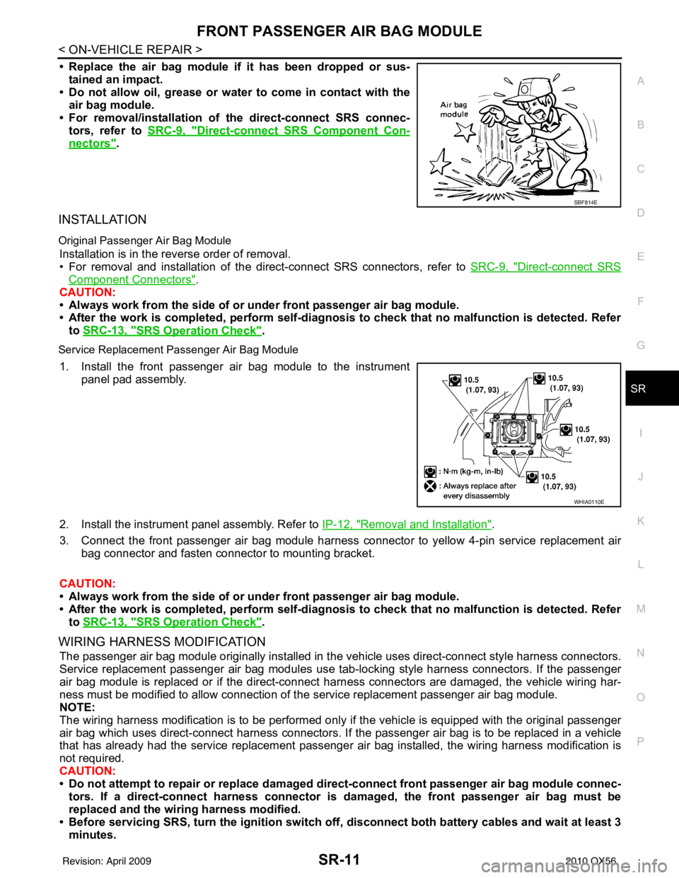
• Replace the air bag module if it has been dropped or sus-
tained an impact.
• Do not allow oil, grease or water to come in contact with the
air bag module.
• For removal/installation of the direct-connect SRS connec- tors, refer to SRC-9, "
Direct-connect SRS Component Con-
nectors".
INSTALLATION
Original Passenger Air Bag Module
Installation is in the reverse order of removal.
• For removal and installation of the direct-connect SRS connectors, refer to SRC-9, "
Direct-connect SRS
Component Connectors".
CAUTION:
• Always work from the side of or under front passenger air bag module.
• After the work is completed, perform self-diagnosi s to check that no malfunction is detected. Refer
to SRC-13, "
SRS Operation Check".
Service Replacement Passenger Air Bag Module
1. Install the front passenger air bag module to the instrument
panel pad assembly.
2. Install the instrument panel assembly. Refer to IP-12, "
Removal and Installation".
3. Connect the front passenger air bag module harness connector to yellow 4-pin service replacement air bag connector and fasten connector to mounting bracket.
CAUTION:
• Always work from the side of or under front passenger air bag module.
• After the work is completed, perform self-diagnosi s to check that no malfunction is detected. Refer
to SRC-13, "
SRS Operation Check".
WIRING HARNESS MODIFICATION
The passenger air bag module originally installed in t he vehicle uses direct-connect style harness connectors.
Service replacement passenger air bag modules use t ab-locking style harness connectors. If the passenger
air bag module is replaced or if the direct-connect harness connectors are damaged, the vehicle wiring har-
ness must be modified to allow connection of t he service replacement passenger air bag module.
NOTE:
The wiring harness modification is to be performed only if the vehicle is equipped with the original passenger
air bag which uses direct-connect harness connectors. If the passenger air bag is to be replaced in a vehicle
that has already had the service replacement passenger air bag installed, the wiring harness modification is
not required.
CAUTION:
• Do not attempt to repair or replace damaged dir ect-connect front passenger air bag module connec-
tors. If a direct-connect harness connector is damaged, the front passenger air bag must be
replaced and the wiri ng harness modified.
• Before servicing SRS, turn the igni tion switch off, disconnect both battery cables and wait at least 3
minutes.
SBF814E
WHIA0110E
Revision: April 20092010 QX56
Page 3536 of 4210
SIDE CURTAIN AIR BAG MODULESR-13
< ON-VEHICLE REPAIR >
C
DE
F
G
I
J
K L
M A
B
SR
N
O P
SIDE CURTAIN AIR BAG MODULE
Removal and InstallationINFOID:0000000005147760
REMOVAL
CAUTION:
• Do not attempt to repair or replace damaged direct-connect SRS component connectors. If a direct- connect harness connector is damage d, the harness must be replaced.
• Before servicing the SRS, turn the ignition switch off, disconnect both battery terminals and wait at
least three minutes.
• When servicing the SRS, do not work from directly in front of air bag module.
• Do not insert any foreign objects (screwdriver, etc.) into air bag module or harness connectors.
• Do not disassemble air bag module.
• Do not expose the air bag modu le to temperatures exceeding 90°C (194 °F).
• Replace side curtain air bag modu le if it has been dropped or
sustained an impact.
• Do not allow oil, grease or water to come in contact with the
air bag module.
1. Disconnect both the negative and positive battey terminals, then wait at least three minutes.
2. Remove headlining. Refer to INT-17, "
Removal and Installation".
3. Disconnect front and rear side curtain air bag module connec- tors.
• For removal/installation of the direct-connect SRS connectors,
refer to SRC-9, "
Direct-connect SRS Component Connectors".
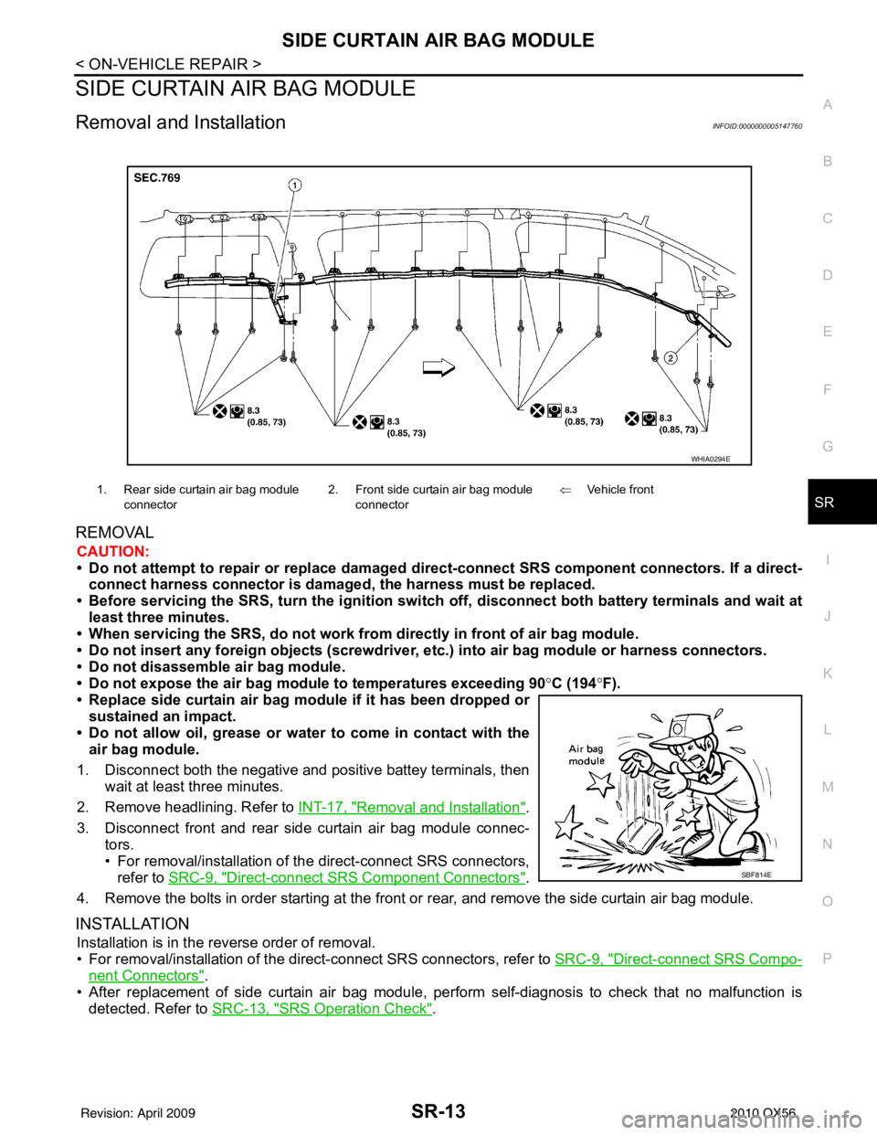
4. Remove the bolts in order starting at the front or rear, and remove the side curtain air bag module.
INSTALLATION
Installation is in the reverse order of removal.
• For removal/installation of the direct-connect SRS connectors, refer to SRC-9, "
Direct-connect SRS Compo-
nent Connectors".
• After replacement of side curtain air bag module, per form self-diagnosis to check that no malfunction is
detected. Refer to SRC-13, "
SRS Operation Check".
1. Rear side curtain air bag module
connector 2. Front side curtain air bag module
connector ⇐
Vehicle front
WHIA0294E
SBF814E
Revision: April 20092010 QX56
Page 3639 of 4210
ST-1
STEERING
C
DE
F
H I
J
K L
M
SECTION ST
A
B
ST
N
O P
CONTENTS
STEERING SYSTEM
PRECAUTION ....... ........................................3
PRECAUTIONS .............................................. .....3
Precaution for Supplemental Restraint System
(SRS) "AIR BAG" and "SEAT BELT PRE-TEN-
SIONER" ............................................................. ......
3
Precaution Necessary for Steering Wheel Rota-
tion After Battery Disconnect ............................... ......
3
PREPARATION ............................................5
PREPARATION .............................................. .....5
Special Service Tool ........................................... ......5
Commercial Service Tool ..........................................6
FUNCTION DIAGNOSIS ...............................7
HEATED STEERING WHEEL ........................ .....7
System Diagram .................................................. ......7
System Description ...................................................7
Component Parts Location ........................................7
Component Description .............................................8
COMPONENT DIAGNOSIS ..........................9
HEATED STEERING WHEEL ........................ .....9
Wiring Diagram ................................................... ......9
SYMPTOM DIAGNOSIS ..............................12
NOISE, VIBRATION AND HARSHNESS
(NVH) TROUBLESHOOTING ........................ ....
12
NVH Troubleshooting Chart ................................ ....12
ON-VEHICLE MAINTENANCE ....................13
POWER STEERING FLUID ........................... ....13
Checking Fluid Level ........................................... ....13
Checking Fluid Leakage ..........................................13
Air Bleeding Hydraulic System ................................13
ON-VEHICLE REPAIR .................................15
STEERING WHEEL ..........................................15
On-Vehicle Inspection and Service ..................... ....15
POWER STEERING OIL PUMP .......................17
On-Vehicle Inspection and Service .........................17
REMOVAL AND INSTALLATION ...............18
STEERING WHEEL ..........................................18
Removal and Installation ..................................... ....18
TILT SYSTEM ...................................................19
Removal and Installation .........................................19
STEERING COLUMN ........................................20
Removal and Installation .........................................20
POWER STEERING GEAR AND LINKAGE ....23
Removal and Installation .........................................23
POWER STEERING OIL PUMP .......................26
Removal and Installation .........................................26
HYDRAULIC LINE ............................................27
Removal and Installation .........................................27
DISASSEMBLY AND ASSEMBLY ..............29
STEERING COLUMN ........................................29
Disassembly and Assembly ................................. ....29
POWER STEERING GEAR AND LINKAGE ....31
Disassembly and Assembly .....................................31
POWER STEERING OIL PUMP .......................34
Disassembly and Assembly .....................................34
SERVICE DATA AND SPECIFICATIONS
(SDS) ............... .......................................... ...
35
SERVICE DATA AND SPECIFICATIONS
(SDS) .................................................................
35
Steering Wheel .................................................... ....35
Revision: April 20092010 QX56
Page 3651 of 4210
POWER STEERING FLUIDST-13
< ON-VEHICLE MAINTENANCE >
C
DE
F
H I
J
K L
M A
B
ST
N
O P
ON-VEHICLE MAINTENANCE
POWER STEERING FLUID
Checking Fluid LevelINFOID:0000000005147865
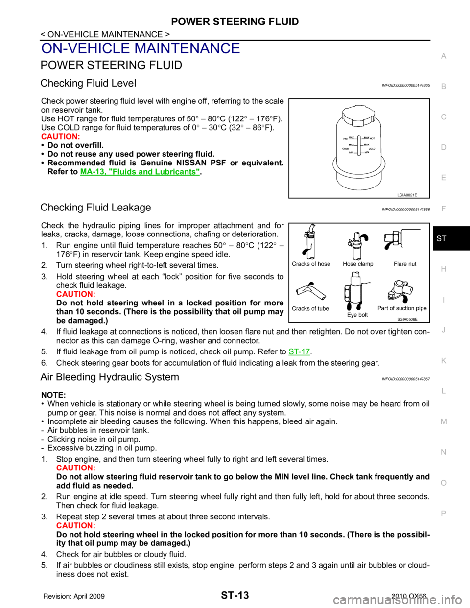
Check power steering fluid level with engine off, referring to the scale
on reservoir tank.
Use HOT range for fluid temperatures of 50 ° – 80 °C (122 ° – 176 °F).
Use COLD range for fluid temperatures of 0 ° – 30 °C (32° – 86°F).
CAUTION:
• Do not overfill.
• Do not reuse any used power steering fluid.
• Recommended fluid is Genuine NISSAN PSF or equivalent. Refer to MA-13, "
Fluids and Lubricants".
Checking Fluid LeakageINFOID:0000000005147866
Check the hydraulic piping lines for improper attachment and for
leaks, cracks, damage, loose connec tions, chafing or deterioration.
1. Run engine until fluid temperature reaches 50 ° – 80° C (122° –
176° F) in reservoir tank. Keep engine speed idle.
2. Turn steering wheel right-to-left several times.
3. Hold steering wheel at each “lock” position for five seconds to check fluid leakage.
CAUTION:
Do not hold steering wheel in a locked position for more
than 10 seconds. (There is the possibility that oil pump may
be damaged.)
4. If fluid leakage at connections is noticed, then loosen flare nut and then retighten. Do not over tighten con- nector as this can damage O-ring, washer and connector.
5. If fluid leakage from oil pump is noticed, check oil pump. Refer to ST-17
.
6. Check steering gear boots for accumulation of fluid indicating a leak from the steering gear.
Air Bleeding Hydraulic SystemINFOID:0000000005147867
NOTE:
• When vehicle is stationary or while steering wheel is being turned slowly, some noise may be heard from oil pump or gear. This noise is normal and does not affect any system.
• Incomplete air bleeding causes the fo llowing. When this happens, bleed air again.
- Air bubbles in reservoir tank.
- Clicking noise in oil pump.
- Excessive buzzing in oil pump.
1. Stop engine, and then turn steering wheel fully to right and left several times. CAUTION:
Do not allow steering fluid reservoir tank to go below the MIN level line. Check tank frequently and
add fluid as needed.
2. Run engine at idle speed. Turn steering wheel fully right and then fully left, hold for about three seconds.
Then check for fluid leakage.
3. Repeat step 2 several times at about three second intervals. CAUTION:
Do not hold steeri ng wheel in the locked position for more than 10 seconds. (There is the possibil-
ity that oil pump may be damaged.)
4. Check for air bubbles or cloudy fluid.
5. If air bubbles or cloudiness still exists, stop engine, perform steps 2 and 3 again until air bubbles or cloud-
iness does not exist.
LGIA0021E
SGIA0506E
Revision: April 20092010 QX56
Page 3655 of 4210
POWER STEERING OIL PUMPST-17
< ON-VEHICLE REPAIR >
C
DE
F
H I
J
K L
M A
B
ST
N
O P
POWER STEERING OIL PUMP
On-Vehicle Inspection and ServiceINFOID:0000000005147869
CHECKING RELIEF OIL PRESSURE
CAUTION:
Before starting work, confirm belt tension is proper.
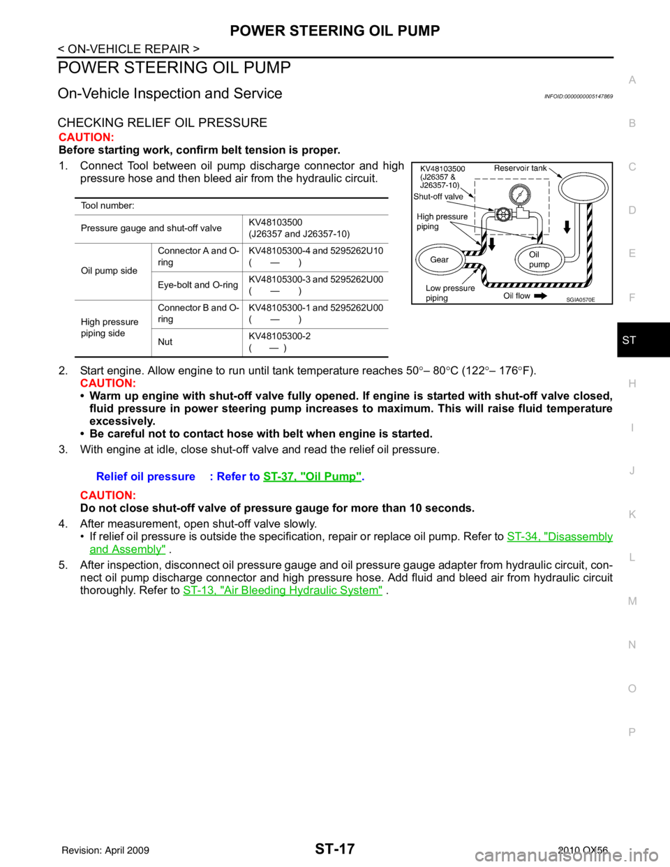
1. Connect Tool between oil pump discharge connector and high pressure hose and then bleed air from the hydraulic circuit.
2. Start engine. Allow engine to run until tank temperature reaches 50 °– 80° C (122° – 176°F).
CAUTION:
• Warm up engine with shut-off valve fully opened. If engine is started with shut-off valve closed,
fluid pressure in power steering pump increases to maximum. This will raise fluid temperature
excessively.
• Be careful not to contact hose with belt when engine is started.
3. With engine at idle, close shut-off valve and read the relief oil pressure.
CAUTION:
Do not close shut-off valve of pressure gauge for more than 10 seconds.
4. After measurement, open shut-off valve slowly. • If relief oil pressure is outside the specification, repair or replace oil pump. Refer to ST-34, "
Disassembly
and Assembly" .
5. After inspection, disconnect oil pressure gauge and oil pressure gauge adapter from hydraulic circuit, con-
nect oil pump discharge connector and high pressure hose. Add fluid and bleed air from hydraulic circuit
thoroughly. Refer to ST-13, "
Air Bleeding Hydraulic System" .
Tool number:
Pressure gauge and shut-off valve KV48103500
(J26357 and J26357-10)
Oil pump side Connector A and O-
ring
KV48105300-4 and 5295262U10
(—)
Eye-bolt and O-ring KV48105300-3 and 5295262U00
(—)
High pressure
piping side Connector B and O-
ring
KV48105300-1 and 5295262U00
(—)
Nut KV48105300-2
( — )
SGIA0570E
Relief oil pressure : Refer to
ST-37, "Oil Pump".
Revision: April 20092010 QX56
Page 3662 of 4210
ST-24
< REMOVAL AND INSTALLATION >
POWER STEERING GEAR AND LINKAGE
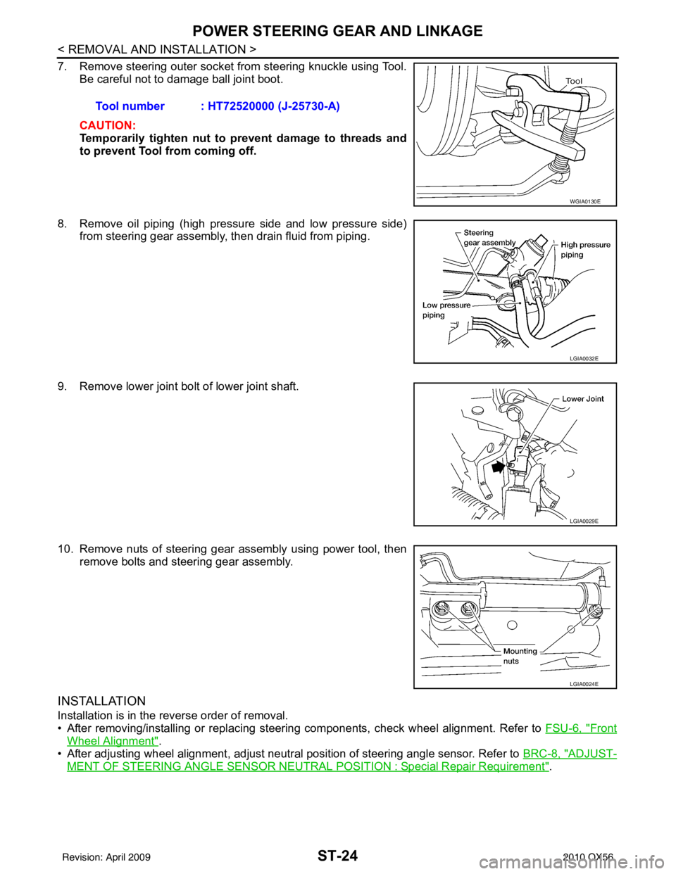
7. Remove steering outer socket from steering knuckle using Tool.Be careful not to damage ball joint boot.
CAUTION:
Temporarily tighten nut to prevent damage to threads and
to prevent Tool from coming off.
8. Remove oil piping (high pressure side and low pressure side) from steering gear assembly, then drain fluid from piping.
9. Remove lower joint bolt of lower joint shaft.
10. Remove nuts of steering gear assembly using power tool, then remove bolts and steering gear assembly.
INSTALLATION
Installation is in the reverse order of removal.
• After removing/installing or replacing steering components, check wheel alignment. Refer to FSU-6, "
Front
Wheel Alignment".
• After adjusting wheel alignment, adjust neutral position of steering angle sensor. Refer to BRC-8, "
ADJUST-
MENT OF STEERING ANGLE SENSOR NEUTRAL POSITION : Special Repair Requirement".
Tool number : HT72520000 (J-25730-A)
WGIA0130E
LGIA0032E
LGIA0029E
LGIA0024E
Revision: April 20092010 QX56
Page 3669 of 4210
POWER STEERING GEAR AND LINKAGEST-31
< DISASSEMBLY AND ASSEMBLY >
C
DE
F
H I
J
K L
M A
B
ST
N
O P
POWER STEERING GEAR AND LINKAGE
Disassembly and AssemblyINFOID:0000000005147877
CAUTION:
• Secure steering gear assembly with a vise, using copper plates or something similar to prevent it
from being damaged. Do not grip cylinder with a vise.
• Before performing disassembly, clean steering gear assembly with kerosene. Be careful not to bring
any kerosene into contact with the di scharge and return port connectors.
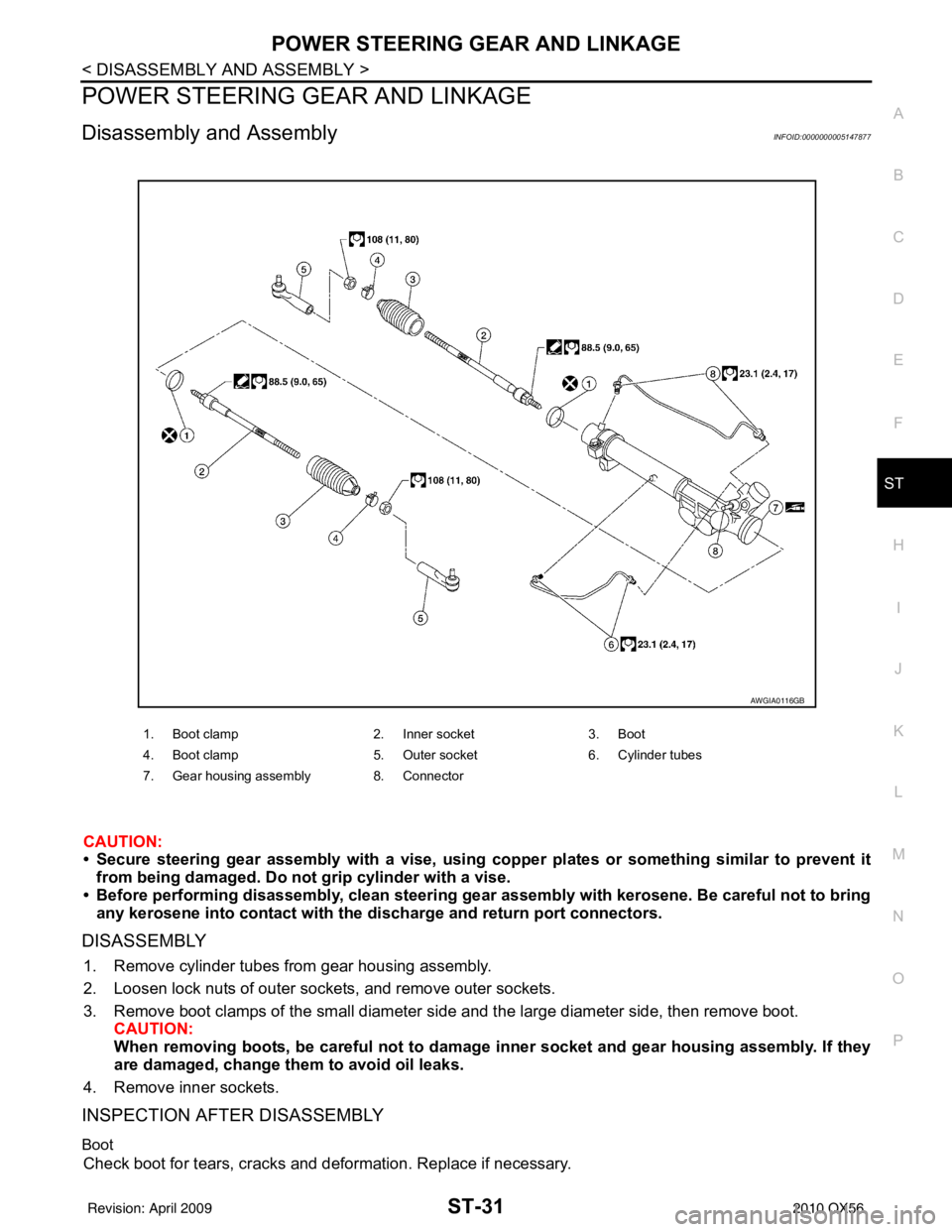
DISASSEMBLY
1. Remove cylinder tubes from gear housing assembly.
2. Loosen lock nuts of outer sockets, and remove outer sockets.
3. Remove boot clamps of the small diameter si de and the large diameter side, then remove boot.
CAUTION:
When removing boots, be careful not to damage inner socket and gear housing assembly. If they
are damaged, change th em to avoid oil leaks.
4. Remove inner sockets.
INSPECTION AFTER DISASSEMBLY
Boot
Check boot for tears, cracks and deformation. Replace if necessary.
1. Boot clamp 2. Inner socket3. Boot
4. Boot clamp 5. Outer socket6. Cylinder tubes
7. Gear housing assembly 8. Connector
AWGIA0116GB
Revision: April 20092010 QX56
Page 3672 of 4210
ST-34
< DISASSEMBLY AND ASSEMBLY >
POWER STEERING OIL PUMP
POWER STEERING OIL PUMP
Disassembly and AssemblyINFOID:0000000005147878
INSPECTION BEFORE DISASSEMBLY
Disassemble the power steering oil pump only if the following items are found.
• Deformed or damaged pulley, bracket, connector or suction pipe.
• Oil leakage from the suction pipe or connector.
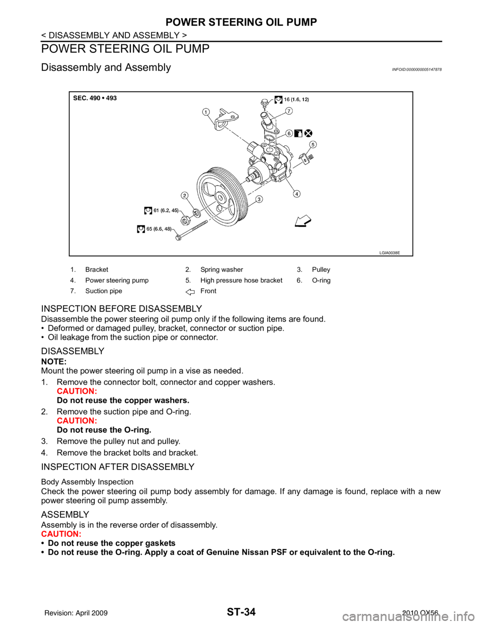
DISASSEMBLY
NOTE:
Mount the power steering oil pump in a vise as needed.
1. Remove the connector bolt, connector and copper washers. CAUTION:
Do not reuse the copper washers.
2. Remove the suction pipe and O-ring. CAUTION:
Do not reuse the O-ring.
3. Remove the pulley nut and pulley.
4. Remove the bracket bolts and bracket.
INSPECTION AFTER DISASSEMBLY
Body Assembly Inspection
Check the power steering oil pump body assembly fo r damage. If any damage is found, replace with a new
power steering oil pump assembly.
ASSEMBLY
Assembly is in the reverse order of disassembly.
CAUTION:
• Do not reuse the copper gaskets
• Do not reuse the O-ring. Apply a coat of Ge nuine Nissan PSF or equivalent to the O-ring.
1. Bracket 2. Spring washer3. Pulley
4. Power steering pump 5. High pressure hose bracket 6. O-ring
7. Suction pipe Front
LGIA0038E
Revision: April 20092010 QX56
Page 3699 of 4210

TM-4
STALL TEST ....................................................155
Inspection and Judgment .................................... ..155
LINE PRESSURE TEST ..................................157
Inspection and Judgment .................................... ..157
ROAD TEST .....................................................159
Description ........................................................... ..159
Check Before Engine Is Started ............................159
Check At Idle ....................................................... ..159
Cruise Test - Part 1 ...............................................160
Cruise Test - Part 2 ...............................................162
Cruise Test - Part 3 ...............................................162
Vehicle Speed When Shifting Gears .....................163
Vehicle Speed When Performing and Releasing
Complete Lock-up .................................................
163
A/T POSITION .................................................164
Adjustment of A/T Position .................................. ..164
Checking of A/T Position .......................................164
ON-VEHICLE REPAIR ...............................165
SHIFT CONTROL SYSTEM ........................... .165
A/T Shift Selector Removal and Installation ..........165
AIR BREATHER HOSE .................................. .166
Removal and Installation ..................................... ..166
OIL PAN ...........................................................170
Oil Pan ................................................................. ..170
CONTROL VALVE WITH TCM ........................172
Control Valve with TCM and A/T Fluid Tempera-
ture Sensor 2 and Plug ........................................ ..
172
REAR OIL SEAL ..............................................184
Rear Oil Seal ....................................................... ..184
FLUID COOLER SYSTEM ...............................185
Exploded View ..................................................... ..185
Removal and Installation .......................................185
REMOVAL AND INSTALLATION ..............186
TRANSMISSION ASSEMBLY ........................ .186
Removal and Installation (2WD) .......................... .186
Removal and Installation (4WD) ...........................188
DISASSEMBLY AND ASSEMBLY ...........192
OVERHAUL ......................................................192
Component .......................................................... .192
Oil Channel ...........................................................199
Location of Adjusting Shims, Needle Bearings,
Thrust Washers and Snap Rings ......................... .
201
DISASSEMBLY .............................................. ..204
Disassembly ......................................................... .204
REPAIR FOR COMPONENT PARTS ..............223
Oil Pump .............................................................. .223
Front Sun Gear, 3rd One-Way Clutch ...................225
Front Carrier, Input Clutch, Rear Internal Gear .....227
Mid Sun Gear, Rear Sun Gear, High and Low Re-
verse Clutch Hub ................................................. .
232
High and Low Reverse Clutch ..............................237
Direct Clutch .........................................................239
ASSEMBLY .................................................... ..242
Assembly (1) ........................................................ .242
Adjustment ............................................................255
Assembly (2) .........................................................257
SERVICE DATA AND SPECIFICATIONS
(SDS) ........ .................................................
265
SERVICE DATA AND SPECIFICATIONS
(SDS) .............................................................. ..
265
General Specification ........................................... .265
Vehicle Speed at Which Gear Shifting Occurs .....265
Vehicle Speed at Which Lock-up Occurs/Releas-
es ......................................................................... .
266
Stall Speed ............................................................266
Line Pressure ........................................................266
Input Speed Sensor ..............................................266
Output Speed Sensor ...........................................266
Reverse Brake ......................................................266
Total End Play .......................................................267
Torque Converter ..................................................267
Revision: April 20092010 QX56
Page 3764 of 4210
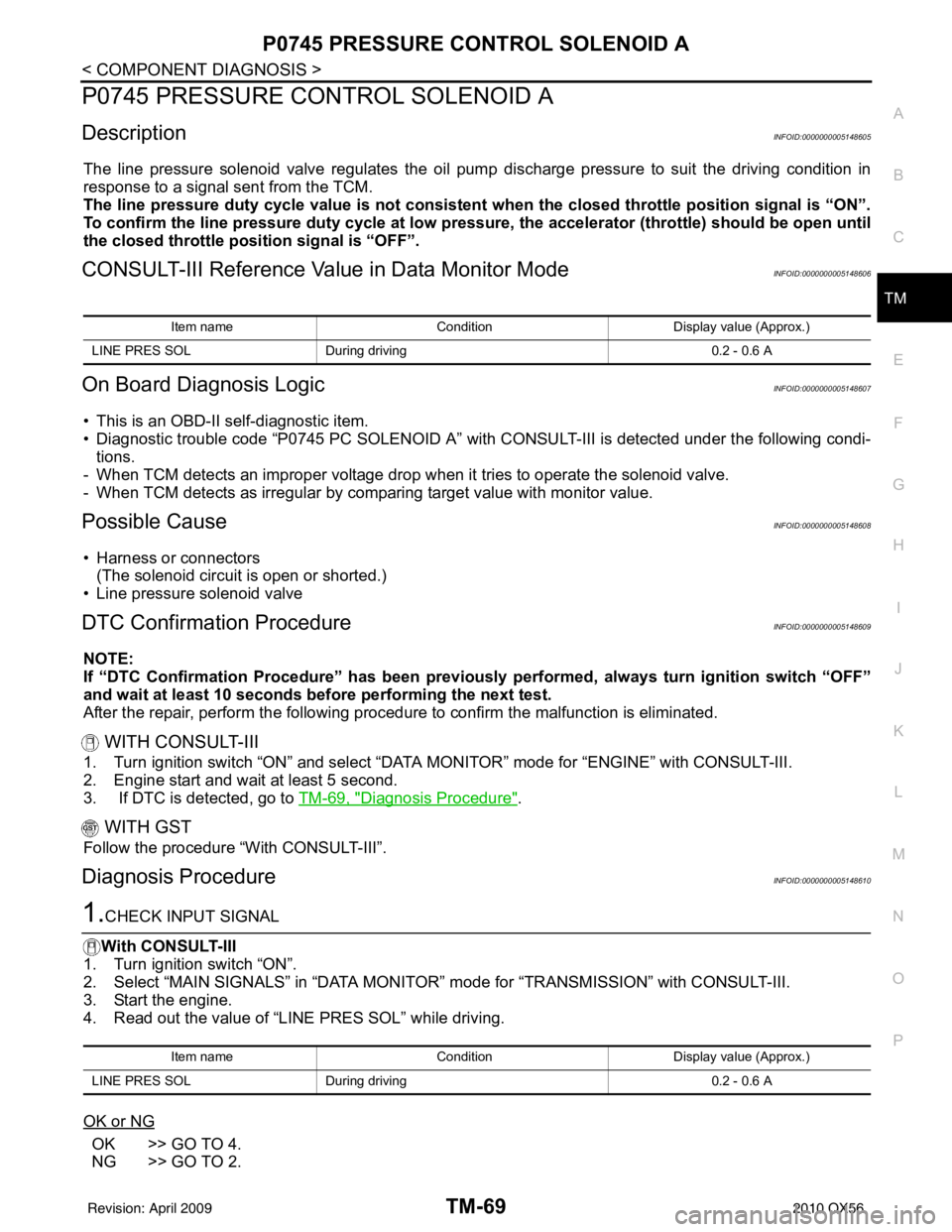
P0745 PRESSURE CONTROL SOLENOID ATM-69
< COMPONENT DIAGNOSIS >
CEF
G H
I
J
K L
M A
B
TM
N
O P
P0745 PRESSURE CONTROL SOLENOID A
DescriptionINFOID:0000000005148605
The line pressure solenoid valve regulates the oil pum p discharge pressure to suit the driving condition in
response to a signal sent from the TCM.
The line pressure duty cycle value is not consistent when the closed throttle position signal is “ON”.
To confirm the line pressure duty cycle at low pressu re, the accelerator (throttle) should be open until
the closed throttle posi tion signal is “OFF”.
CONSULT-III Reference Val ue in Data Monitor ModeINFOID:0000000005148606
On Board Diagnosis LogicINFOID:0000000005148607
• This is an OBD-II self-diagnostic item.
• Diagnostic trouble code “P0745 PC SOLENOID A” with CONSULT-III is detected under the following condi-
tions.
- When TCM detects an improper voltage drop when it tries to operate the solenoid valve.
- When TCM detects as irregular by comparing target value with monitor value.
Possible CauseINFOID:0000000005148608
• Harness or connectors (The solenoid circuit is open or shorted.)
• Line pressure solenoid valve
DTC Confirmation ProcedureINFOID:0000000005148609
NOTE:
If “DTC Confirmation Procedure” has been previously performed, always turn ignition switch “OFF”
and wait at least 10 seconds before performing the next test.
After the repair, perform the following procedure to confirm the malfunction is eliminated.
WITH CONSULT-III
1. Turn ignition switch “ON” and select “DATA MONITOR” mode for “ENGINE” with CONSULT-III.
2. Engine start and wait at least 5 second.
3. If DTC is detected, go to TM-69, "
Diagnosis Procedure".
WITH GST
Follow the procedure “With CONSULT-III”.
Diagnosis ProcedureINFOID:0000000005148610
1.CHECK INPUT SIGNAL
With CONSULT-III
1. Turn ignition switch “ON”.
2. Select “MAIN SIGNALS” in “DATA MONITOR” mode for “TRANSMISSION” with CONSULT-III.
3. Start the engine.
4. Read out the value of “LINE PRES SOL” while driving.
OK or NG
OK >> GO TO 4.
NG >> GO TO 2.
Item name Condition Display value (Approx.)
LINE PRES SOL During driving 0.2 - 0.6 A
Item nameCondition Display value (Approx.)
LINE PRES SOL During driving 0.2 - 0.6 A
Revision: April 20092010 QX56