wiring diagram INFINITI QX56 2010 Factory Service Manual
[x] Cancel search | Manufacturer: INFINITI, Model Year: 2010, Model line: QX56, Model: INFINITI QX56 2010Pages: 4210, PDF Size: 81.91 MB
Page 3647 of 4210

HEATED STEERING WHEELST-9
< COMPONENT DIAGNOSIS >
C
DE
F
H I
J
K L
M A
B
ST
N
O P
COMPONENT DIAGNOSIS
HEATED STEERING WHEEL
Wiring DiagramINFOID:0000000005147863
ABGWA0009GB
Revision: April 20092010 QX56
Page 3676 of 4210
STR-1
ENGINE
C
DE
F
G H
I
J
K L
M
SECTION STR
A
STR
N
O P
CONTENTS
STARTING SYSTEM
PRECAUTION ....... ........................................2
PRECAUTIONS .............................................. .....2
Precaution for Supplemental Restraint System
(SRS) "AIR BAG" and "SEAT BELT PRE-TEN-
SIONER" ............................................................. ......
2
Precaution Necessary for Steering Wheel Rota-
tion After Battery Disconnect ............................... ......
2
Precaution for Power Generation Variable Voltage
Control System ..........................................................
3
PREPARATION ............................................4
PREPARATION .............................................. .....4
Special Service Tool ........................................... ......4
Commercial Service Tool ..........................................4
BASIC INSPECTION ....................................5
DIAGNOSIS AND REPAIR WORKFLOW ..... .....5
Work Flow ........................................................... ......5
FUNCTION DIAGNOSIS ...............................8
STARTING SYSTEM ...................................... .....8
System Diagram .................................................. ......8
System Description ...................................................8
Component Parts Location ........................................8
Component Description ............................................9
COMPONENT DIAGNOSIS .........................10
B TERMINAL CIRCUIT .....................................10
Description ........................................................... ....10
Diagnosis Procedure ...............................................10
S CONNECTOR CIRCUIT .................................12
Description ...............................................................12
Diagnosis Procedure ...............................................12
STARTING SYSTEM .........................................14
Wiring Diagram .................................................... ....14
SYMPTOM DIAGNOSIS ..............................18
STARTING SYSTEM .........................................18
Symptom Table ................................................... ....18
ON-VEHICLE REPAIR .................................19
STARTER MOTOR ...........................................19
Removal and Installation ..................................... ....19
SERVICE DATA AND SPECIFICATIONS
(SDS) ............... .......................................... ...
20
STARTER MOTOR ...........................................20
Starter .................................................................. ....20
Revision: April 20092010 QX56
Page 3685 of 4210
STR-10
< COMPONENT DIAGNOSIS >
B TERMINAL CIRCUIT
COMPONENT DIAGNOSIS
B TERMINAL CIRCUIT
DescriptionINFOID:0000000005149554
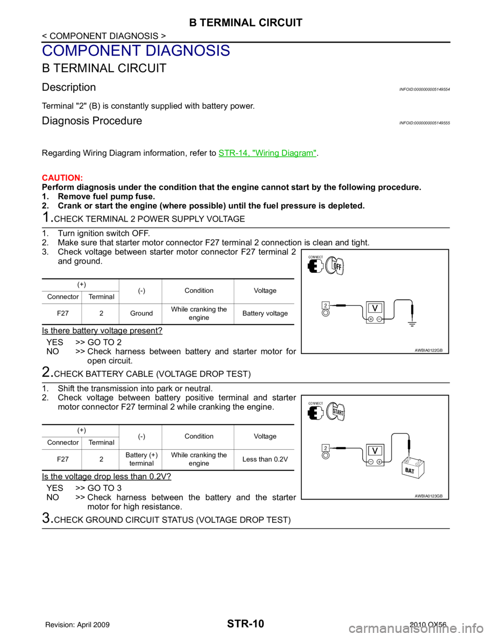
Terminal "2" (B) is constantly supplied with battery power.
Diagnosis ProcedureINFOID:0000000005149555
Regarding Wiring Diagram information, refer to STR-14, "Wiring Diagram".
CAUTION:
Perform diagnosis under the condi tion that the engine cannot start by the following procedure.
1. Remove fuel pump fuse.
2. Crank or start the engine (where possible) until the fuel pressure is depleted.
1.CHECK TERMINAL 2 POWER SUPPLY VOLTAGE
1. Turn ignition switch OFF.
2. Make sure that starter motor connector F27 terminal 2 connection is clean and tight.
3. Check voltage between starter motor connector F27 terminal 2
and ground.
Is there battery voltage present?
YES >> GO TO 2
NO >> Check harness between battery and starter motor for open circuit.
2.CHECK BATTERY CABLE (VOLTAGE DROP TEST)
1. Shift the transmission into park or neutral.
2. Check voltage between battery positive terminal and starter motor connector F27 terminal 2 while cranking the engine.
Is the voltage drop less than 0.2V?
YES >> GO TO 3
NO >> Check harness between the battery and the starter motor for high resistance.
3.CHECK GROUND CIRCUIT STATUS (VOLTAGE DROP TEST)
(+) (-)Condition Voltage
Connector Terminal
F27 2 Ground While cranking the
engine Battery voltage
AWBIA0122GB
(+)
(-)Condition Voltage
Connector Terminal
F27 2 Battery (+)
terminal While cranking the
engine Less than 0.2V
AWBIA0123GB
Revision: April 20092010 QX56
Page 3687 of 4210
STR-12
< COMPONENT DIAGNOSIS >
S CONNECTOR CIRCUIT
S CONNECTOR CIRCUIT
DescriptionINFOID:0000000005149556
Terminal "1" (S) is the power supply for the starter motor magnetic switch. Terminal 1 is supplied with power
when the ignition switch is turned to the START position while the selector lever is in the P or N position.
Diagnosis ProcedureINFOID:0000000005149557
Regarding Wiring Diagram information, refer to STR-14, "Wiring Diagram".
CAUTION:
Perform diagnosis under the condi tion that engine cannot start by the following procedure.
1. Remove fuel pump fuse.
2. Crank or start the engine (where possi ble) until the fuel pressure is released.
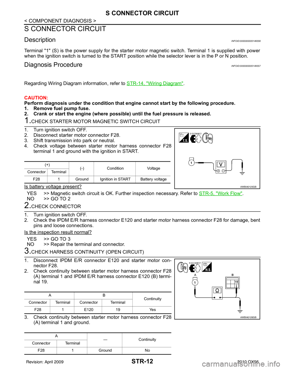
1.CHECK STARTER MOTOR MAGNETIC SWITCH CIRCUIT
1. Turn ignition switch OFF.
2. Disconnect starter motor connector F28.
3. Shift transmission into park or neutral.
4. Check voltage between starter motor harness connector F28 terminal 1 and ground with the ignition in START.
Is battery voltage present?
YES >> Magnetic switch circuit is OK. Further inspection necessary. Refer to STR-5, "Work Flow".
NO >> GO TO 2
2.CHECK CONNECTOR
1. Turn ignition switch OFF.
2. Check the IPDM E/R harness connector E120 and st arter motor harness connector F28 for damage, bent
pins and loose connections.
Is the inspection result normal?
YES >> GO TO 3
NO >> Repair the terminal and connector.
3.CHECK HARNESS CONTI NUITY (OPEN CIRCUIT)
1. Disconnect IPDM E/R connector E120 and starter motor con- nector F28.
2. Check continuity between starter motor harness connector F28
(A) terminal 1 and IPDM E/R harness connector E120 (B) termi-
nal 19.
3. Check continuity between starter motor harness connector F28 (A) terminal 1 and ground.
(+) (-)Condition Voltage
Connector Terminal
F28 1 Ground Ignition in START Battery voltage
AWBIA0125GB
AB Continuity
Connector Terminal Connector Terminal
F28 1E120 19 Yes
A —Contin u it y
Connector Terminal
F28 1Ground No
AWBIA0126GB
Revision: April 20092010 QX56
Page 3689 of 4210

STR-14
< COMPONENT DIAGNOSIS >
STARTING SYSTEM
STARTING SYSTEM
Wiring DiagramINFOID:0000000005149558
ABBWA0118GB
Revision: April 20092010 QX56
Page 3698 of 4210
TM-3
CEF
G H
I
J
K L
M A
B
TM
N
O P
Diagnosis Procedure ...........................................
....
80
P1752 INPUT CLUTCH SOLENOID ..................82
Description .......................................................... ....82
CONSULT-III Reference Value in Data Monitor
Mode ................................................................... ....
82
On Board Diagnosis Logic ......................................82
Possible Cause .......................................................82
DTC Confirmation Procedure ..................................82
Diagnosis Procedure ...............................................82
P1757 FRONT BRAKE SOLENOID ...................84
Description .......................................................... ....84
CONSULT-III Reference Value in Data Monitor
Mode ................................................................... ....
84
On Board Diagnosis Logic ......................................84
Possible Cause .......................................................84
DTC Confirmation Procedure ..................................84
Diagnosis Procedure ...............................................84
P1762 DIRECT CLUTCH SOLENOID ................86
Description .......................................................... ....86
CONSULT-III Reference Value in Data Monitor
Mode ................................................................... ....
86
On Board Diagnosis Logic ......................................86
Possible Cause .......................................................86
DTC Confirmation Procedure ..................................86
Diagnosis Procedure ...............................................86
P1767 HIGH AND LOW REVERSE CLUTCH
SOLENOID .........................................................
88
Description .......................................................... ....88
CONSULT-III Reference Value in Data Monitor
Mode ................................................................... ....
88
On Board Diagnosis Logic ......................................88
Possible Cause .......................................................88
DTC Confirmation Procedure ..................................88
Diagnosis Procedure ...............................................88
P1772 LOW COAST BRAKE SOLENOID .........90
Description .......................................................... ....90
CONSULT-III Reference Value in Data Monitor
Mode ................................................................... ....
90
On Board Diagnosis Logic ......................................90
Possible Cause .......................................................90
DTC Confirmation Procedure ..................................90
Diagnosis Procedure ...............................................90
P1774 LOW COAST BRAKE SOLENOID .........92
Description .......................................................... ....92
CONSULT-III Reference Value in Data Monitor
Mode ................................................................... ....
92
On Board Diagnosis Logic ......................................92
Possible Cause .......................................................92
DTC Confirmation Procedure ..................................92
Diagnosis Procedure ...............................................93
MAIN POWER SUPPLY AND GROUND CIR-
CUIT ....................................................................
94
Diagnosis Procedure ........................................... ....94
CLOSED THROTTLE POSITION AND WIDE
OPEN THROTTLE POSITION CIRCUIT ...........
96
CONSULT-III Reference Value in Data Monitor
Mode .................................................................... ....
96
Diagnosis Procedure ...............................................96
BRAKE SIGNAL CIRCUIT ................................97
CONSULT-III Reference Va lue in Data Monitor
Mode .................................................................... ....
97
Diagnosis Procedure ...............................................97
TOW MODE SWITCH .......................................98
Description ...............................................................98
Diagnosis Procedure ...............................................98
A/T SHIFT LOCK SYSTEM ...............................99
Description ...............................................................99
Terminals And Reference Values ............................99
Wiring Diagram - A/T SH IFT LOCK SYSTEM - .....100
Component Inspection ......................................... ..103
ECU DIAGNOSIS .......................................106
TCM .................................................................106
Reference Value .................................................. ..106
Wiring Diagram — A/T CONTROL SYSTEM — .. ..108
Fail-Safe .............................................................. ..117
DTC Inspection Priority Chart ................................119
DTC No. Index .......................................................119
DTC Alphabetical Index .........................................120
SYMPTOM DIAGNOSIS ............................121
SYSTEM SYMPTOM .......................................121
Symptom Table ................................................... ..121
PRECAUTION ............................................143
PRECAUTIONS ...............................................143
Precaution for Supplemental Restraint System
(SRS) "AIR BAG" and "SEAT BELT PRE-TEN-
SIONER" ............................................................. ..
143
Precaution for On Board Diagnosis (OBD) System
of A/T and Engine ................................................ ..
143
Precaution .............................................................143
Service Notice or Precaution .................................144
PREPARATION .........................................146
PREPARATION ...............................................146
Special Service Tool ............................................ ..146
Commercial Service Tool ......................................147
ON-VEHICLE MAINTENANCE ..................148
A/T FLUID .......................................................148
Checking the A/T Fluid (ATF) .............................. ..148
Changing the A/T Fluid (ATF) ................................150
A/T FLUID COOLER .......................................152
A/T Fluid Cooler Cleaning .....................................152
Inspection ..............................................................154
Revision: April 20092010 QX56
Page 3716 of 4210
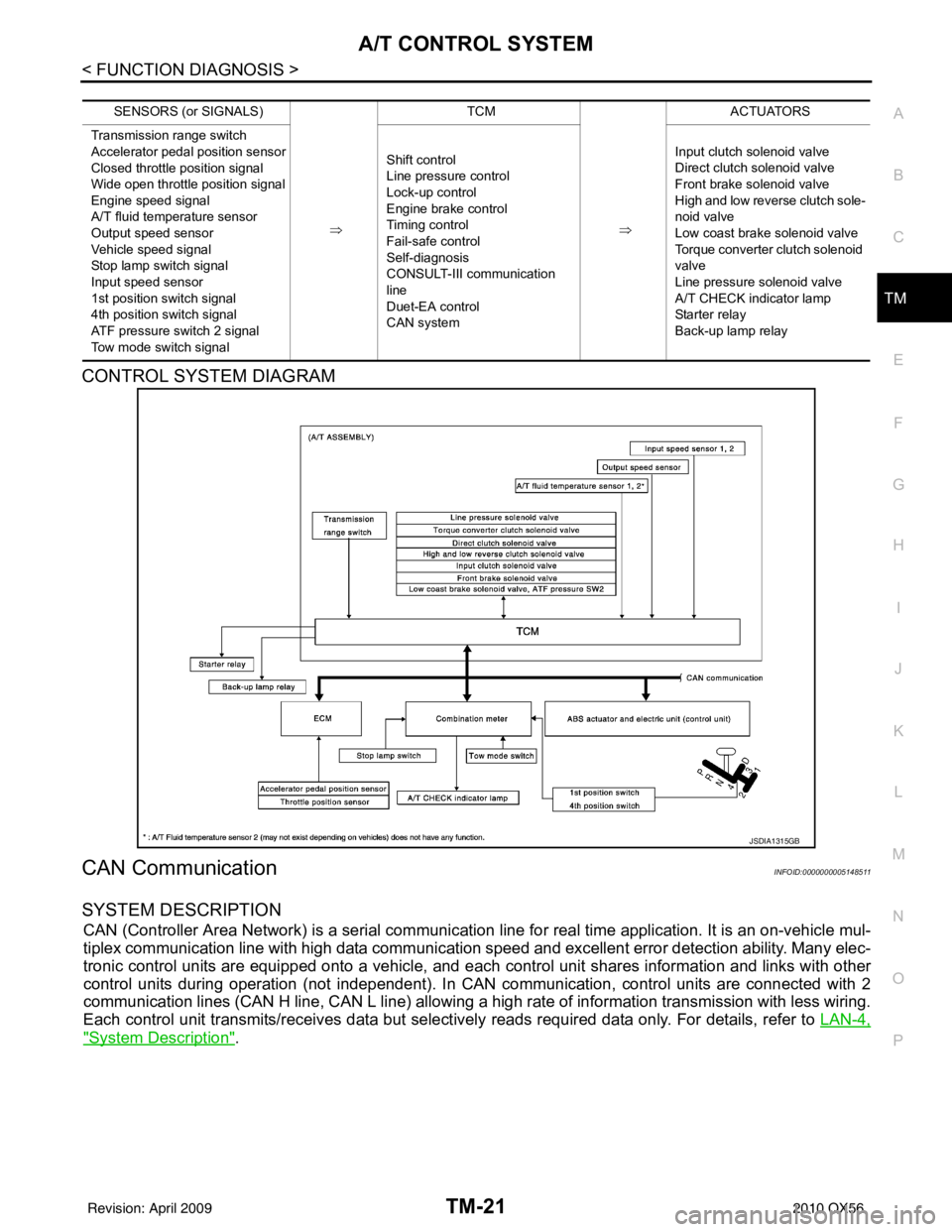
A/T CONTROL SYSTEMTM-21
< FUNCTION DIAGNOSIS >
CEF
G H
I
J
K L
M A
B
TM
N
O P
CONTROL SYSTEM DIAGRAM
CAN CommunicationINFOID:0000000005148511
SYSTEM DESCRIPTION
CAN (Controller Area Network) is a serial communication line for real time application. It is an on-vehicle mul-
tiplex communication line with high data communication speed and excellent error detection ability. Many elec-
tronic control units are equipped onto a vehicle, and each control unit shares information and links with other
control units during operation (not independent). In CAN communication, control units are connected with 2
communication lines (CAN H line, CAN L line) allowing a high rate of information transmission with less wiring.
Each control unit transmits/receives data but selectively reads required data only. For details, refer to LAN-4,
"System Description".
SENSORS (or SIGNALS)
⇒TCM
⇒ACTUATORS
Transmission range switch
Accelerator pedal position sensor
Closed throttle position signal
Wide open throttle position signal
Engine speed signal
A/T fluid temperature sensor
Output speed sensor
Vehicle speed signal
Stop lamp switch signal
Input speed sensor
1st position switch signal
4th position switch signal
ATF pressure switch 2 signal
Tow mode switch signal Shift control
Line pressure control
Lock-up control
Engine brake control
Timing control
Fail-safe control
Self-diagnosis
CONSULT-III co
mmunication
line
Duet-EA control
CAN system Input clutch solenoid valve
Direct clutch solenoid valve
Front brake solenoid valve
High and low reverse clutch sole-
noid valve
Low coast brake solenoid valve
Torque converter clutch solenoid
valve
Line pressure solenoid valve
A/T CHECK indicator lamp
Starter relay
Back-up lamp relay
JSDIA1315GB
Revision: April 20092010 QX56
Page 3795 of 4210

TM-100
< COMPONENT DIAGNOSIS >
A/T SHIFT LOCK SYSTEM
Wiring Diagram - A/T SHIFT LOCK SYSTEM -
INFOID:0000000005148685
ABDWA0116GB
Revision: April 20092010 QX56
Page 3803 of 4210

TM-108
< ECU DIAGNOSIS >
TCM
Wiring Diagram —A/T CONTROL SYSTEM —
INFOID:0000000005148689
ABDWA0117GB
Revision: April 20092010 QX56
Page 3980 of 4210

VTL-18
< ON-VEHICLE REPAIR >
HEATER & COOLING UNIT ASSEMBLY
1. Move the two front seats to the rear most position on the seat track.
2. Disconnect the battery negative terminal and battery positive terminal.
3. Discharge the refrigerant from the A/C system. Refer to HA-20, "
HFC-134a (R-134a) Service Procedure".
4. Drain the coolant from the engine cooling system. Refer to CO-11, "
Changing Engine Coolant".
5. Disconnect the front heater hoses from the front heater core.
6. Disconnect the high/low pressure pipes from the front expansion valve.
7. Remove the instrument panel and console panel. Refer to IP-12, "
Removal and Installation".
8. Disconnect the instrument panel wire harness at the RH and LH in-line connector brackets, and the fuse block (J/B) electrical connectors. Refer to PG-9, "
Wiring Diagram — Battery Power Supply —".
9. Disconnect the steering member from each side of the vehicle body.
10. Remove the front heater and cooling unit assembly with it attached to the steering member, from the vehi-
cle.
CAUTION:
Use care not to damage the seats and interior tr im panels when removing the front heater and
cooling unit assembly with it at tached to the steering member.
11. Remove the front heater and cooling unit assembly from the steering member.
Installation
Installation is in the reverse order of removal.
CAUTION:
• Replace the O-ring of the low-pressure pipe and high-pressure pipe with a new one, and apply com-
pressor oil to it when installing it.
• After charging the refrigerant, check for leaks.
NOTE:
• Fill the engine cooling system with the specified coolant mixture. Refer to CO-11, "
Changing Engine Cool-
ant".
• Recharge the A/C system. Refer to HA-20, "
HFC-134a (R-134a) Service Procedure".
REAR HEATER AND COOLING UNIT ASSEMBLY
Removal
1. Discharge the refrigerant from the A/C system. Refer to HA-20, "HFC-134a (R-134a) Service Procedure".
2. Drain the coolant from the engine cooling system. Refer to CO-11, "
Changing Engine Coolant".
3. Remove the luggage side finisher lower and upper RH. Refer to INT-19, "
Removal and Installation".
4. Disconnect the rear heater core hoses from the rear heater core.
5. Disconnect the rear A/C pipes from the rear expansion valve.
6. Disconnect the following electrical connectors: • Rear blower motor
• Rear variable blower control
• Rear air mix door motor
• Rear mode door motor
7. Disconnect the ducts and drain tube from the rear heater and cooling unit assembly.
8. Remove the rear heater and cooling unit assembly.
Installation
Installation is in the reverse order of removal.
CAUTION:
• Replace the O-ring of the low-pressure pipe and high-pressure pipe with a new one, and apply com-
pressor oil to it when installing it.
• After charging the refrigerant, check for leaks.
NOTE:
• Fill the engine cooling system with the specified coolant mixture. Refer to CO-11, "
Changing Engine Cool-
ant".
• Recharge the A/C system. Refer to HA-20, "
HFC-134a (R-134a) Service Procedure".
Revision: April 20092010 QX56