engine INFINITI QX56 2010 Factory Service Manual
[x] Cancel search | Manufacturer: INFINITI, Model Year: 2010, Model line: QX56, Model: INFINITI QX56 2010Pages: 4210, PDF Size: 81.91 MB
Page 2175 of 4210

DRIVE SHAFTFAX-9
< REMOVAL AND INSTALLATION >
CEF
G H
I
J
K L
M A
B
FA X
N
O P
DRIVE SHAFT
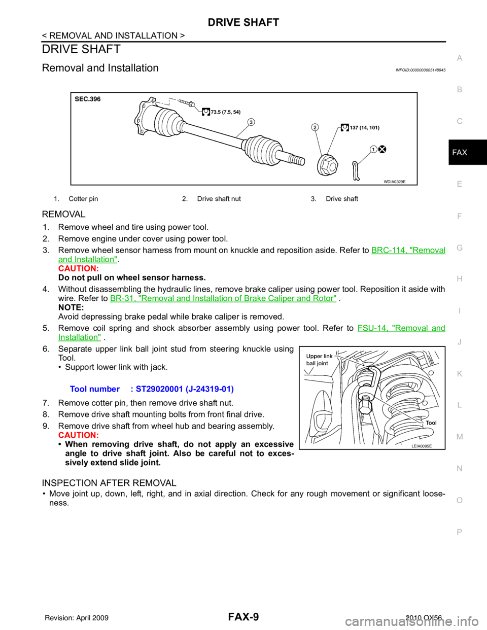
Removal and InstallationINFOID:0000000005148945
REMOVAL
1. Remove wheel and tire using power tool.
2. Remove engine under cover using power tool.
3. Remove wheel sensor harness from mount on knuckle and reposition aside. Refer to BRC-114, "
Removal
and Installation".
CAUTION:
Do not pull on wheel sensor harness.
4. Without disassembling the hydraulic lines, remove brake caliper using power tool. Reposition it aside with wire. Refer to BR-31, "
Removal and Installation of Brake Caliper and Rotor" .
NOTE:
Avoid depressing brake pedal while brake caliper is removed.
5. Remove coil spring and shock absorber assembly using power tool. Refer to FSU-14, "
Removal and
Installation" .
6. Separate upper link ball joint stud from steering knuckle using Tool.
• Support lower link with jack.
7. Remove cotter pin, then remove drive shaft nut.
8. Remove drive shaft mounting bolts from front final drive.
9. Remove drive shaft from wheel hub and bearing assembly. CAUTION:
• When removing drive shaf t, do not apply an excessive
angle to drive shaft joint. Also be careful not to exces-
sively extend slide joint.
INSPECTION AFTER REMOVAL
• Move joint up, down, left, right, and in axial directi on. Check for any rough movement or significant loose-
ness.
1. Cotter pin 2. Drive shaft nut3. Drive shaft
WDIA0329E
Tool number : ST29020001 (J-24319-01)
LEIA0095E
Revision: April 20092010 QX56
Page 2183 of 4210

FL-1
ENGINE
C
DE
F
G H
I
J
K L
M
SECTION FL
A
FL
N
O P
CONTENTS
FUEL SYSTEM
PRECAUTION ....... ........................................2
PRECAUTIONS .............................................. .....2
Precaution for Supplemental Restraint System
(SRS) "AIR BAG" and "SEAT BELT PRE-TEN-
SIONER" ............................................................. ......
2
Precaution Necessary for Steering Wheel Rota-
tion After Battery Disconnect ............................... ......
2
FUEL SYSTEM ....................................................4
General Precaution ............................................. ......4
PREPARATION ............................................5
PREPARATION .............................................. .....5
Special Service Tool ........................................... ......5
Commercial Service Tool ..........................................5
BASIC INSPECTION ....................................6
FUEL SYSTEM ............................................... .....6
Checking Fuel Line ............................................. ......6
REMOVAL AND INSTALLATION ................7
FUEL LEVEL SENSOR UNIT, FUEL FILTER
AND FUEL PUMP ASSEMBLY .........................
7
Removal and Installation ..................................... .....7
FUEL TANK ......................................................11
Removal and Installation ..................................... ....11
DISASSEMBLY AND ASSEMBLY ..............16
FUEL LEVEL SENSOR UNIT, FUEL FILTER
AND FUEL PUMP ASSEMBLY ........................
16
Disassembly and Assembly ................................. ....16
SERVICE DATA AND SPECIFICATIONS
(SDS) ............... .......................................... ...
17
SERVICE DATA AND SPECIFICATIONS
(SDS) .................................................................
17
Standard and Limit .............................................. ....17
Revision: April 20092010 QX56
Page 2184 of 4210

FL-2
< PRECAUTION >
PRECAUTIONS
PRECAUTION
PRECAUTIONS
Precaution for Supplemental Restraint System (SRS) "AIR BAG" and "SEAT BELT
PRE-TENSIONER"
INFOID:0000000005390742
The Supplemental Restraint System such as “A IR BAG” and “SEAT BELT PRE-TENSIONER”, used along
with a front seat belt, helps to reduce the risk or severity of injury to the driver and front passenger for certain
types of collision. This system includes seat belt switch inputs and dual stage front air bag modules. The SRS
system uses the seat belt switches to determine the front air bag deployment, and may only deploy one front
air bag, depending on the severity of a collision and w hether the front occupants are belted or unbelted.
Information necessary to service the system safely is included in the SR and SB section of this Service Man-
ual.
WARNING:
• To avoid rendering the SRS inopera tive, which could increase the risk of personal injury or death in
the event of a collision which would result in air bag inflation, all maintenance must be performed by
an authorized NISSAN/INFINITI dealer.
• Improper maintenance, including in correct removal and installation of the SRS, can lead to personal
injury caused by unintent ional activation of the system. For re moval of Spiral Cable and Air Bag
Module, see the SR section.
• Do not use electrical test equipmen t on any circuit related to the SRS unless instructed to in this
Service Manual. SRS wiring harn esses can be identified by yellow and/or orange harnesses or har-
ness connectors.
PRECAUTIONS WHEN USING POWER TOOLS (AIR OR ELECTRIC) AND HAMMERS
WARNING:
• When working near the Airbag Diagnosis Sensor Unit or other Airbag System sensors with the Igni-
tion ON or engine running, DO NOT use air or electri c power tools or strike near the sensor(s) with a
hammer. Heavy vibration could activate the sensor( s) and deploy the air bag(s), possibly causing
serious injury.
• When using air or electric power tools or hammers , always switch the Ignition OFF, disconnect the
battery, and wait at least 3 minu tes before performing any service.
Precaution Necessary for Steering W heel Rotation After Battery Disconnect
INFOID:0000000005390743
NOTE:
• This Procedure is applied only to models with Intelligent Key system and NATS (NISSAN ANTI-THEFT SYS-
TEM).
• Remove and install all control units after disconnecting both battery cables with the ignition knob in the
″LOCK ″ position.
• Always use CONSULT-III to perform self-diagnosis as a part of each function inspection after finishing work.
If DTC is detected, perform trouble diagnosis according to self-diagnostic results.
For models equipped with the Intelligent Key system and NATS, an electrically controlled steering lock mech-
anism is adopted on the key cylinder.
For this reason, if the battery is disconnected or if the battery is discharged, the steering wheel will lock and
steering wheel rotation will become impossible.
If steering wheel rotation is required when battery pow er is interrupted, follow the procedure below before
starting the repair operation.
OPERATION PROCEDURE
1. Connect both battery cables. NOTE:
Supply power using jumper cables if battery is discharged.
2. Use the Intelligent Key or mechanical key to turn the ignition switch to the ″ACC ″ position. At this time, the
steering lock will be released.
3. Disconnect both battery cables. The steering lock will remain released and the steering wheel can be rotated.
4. Perform the necessary repair operation.
Revision: April 20092010 QX56
Page 2186 of 4210

FL-4
< PRECAUTION >
FUEL SYSTEM
FUEL SYSTEM
General PrecautionINFOID:0000000005149530
WARNING:
When replacing fuel line parts, be sure to observe the following.
• Put a “CAUTION: FLAMMABLE” sign in the workshop.
• Be sure to work in a well ventilate d area and furnish workshop with a CO
2 fire extinguisher.
• Do not smoke while servicing fuel system. Keep open flames and sparks away from the work area.
CAUTION:
• Before removing fuel line parts, carry out the following procedures:
- Put drained fuel in an explosi on-proof container and put the lid on securely. Keep the container in
safe area.
- Release fuel pressure from the fuel lines. Refer to EC-489, "
Fuel Pressure Check" .
- Disconnect the battery negative terminal.
• Always replace O-rings and clamps with new ones.
• Do not kink or twist hoses when they are being installed.
• After connecting the fuel t ube quick connectors, make sure
the quick connectors are secure.
Ensure that the connector and resin tube do not contact any
adjacent parts.
• After installing tubes, make su re there is no fuel leakage at
connections in the following steps.
- Apply fuel pressure to fuel lines with turning ignition switch
ON (with engine stopped). Th en check for fuel leaks at con-
nections.
- Start the engine and rev it up and check for fuel leaks at con-
nections.
• Use only a Genuine NISSAN fuel filler cap as a replacement. If an incorrect fuel filler cap is used, the MIL may come on.
• For servicing “Evaporative Emission System” parts, refer to EC-493, "
Removal and Installation" .
• For servicing “On Board Refueling Vapor Recovery (ORVR)”
parts, refer to EC-491, "
How to Detect Fuel Vapor Leakage" .
PBIC1268E
Revision: April 20092010 QX56
Page 2192 of 4210

FL-10
< REMOVAL AND INSTALLATION >
FUEL LEVEL SENSOR UNIT, FUEL FILTER AND FUEL PUMP ASSEMBLY
- After connecting the quick connector, make sure that the connec-
tion is secure by checking as follows:
- Pull the tube and the connector to make sure they are securely
connected.
- Visually inspect the connector to make sure the two retainer tabs are securely connected.
INSPECTION AFTER INSTALLATION
1. Turn the ignition switch ON but do not start engi ne, then check the fuel pipes and hose connections for
leaks while applying fuel pressure to the system.
2. Start the engine and rev it above idle speed, then check t hat there are no fuel leaks at any of the fuel pipe
and hose connections.
PBIC1653E
Revision: April 20092010 QX56
Page 2197 of 4210

FUEL TANKFL-15
< REMOVAL AND INSTALLATION >
C
DE
F
G H
I
J
K L
M A
FL
NP
O
21. If necessary, remove the lock ring using Tool.
22. If necessary, remove the fuel level sensor, fuel filter, and fuel
pump assembly. Discard the fuel level sensor, fuel filter, and fuel
pump assembly O-ring.
CAUTION:
• Do not bend the float arm during removal.
• Avoid impacts such as droppi ng when handling the com-
ponents.
INSTALLATION
Installation is in the reverse order of removal.
• For installation, use a new fuel level sensor, fuel filter, and fuel pump assembly O-ring.
• Connect the quick connector as follows:
- Check the connection for any damage or foreign materials.
- Align the connector with the pipe, t hen insert the connector straight into the pipe until a click is heard.
- After connecting the quick connector, make sure that the connec-
tion is secure by checking as follows:
- Pull the tube and the connector to make sure they are securely connected.
- Visually inspect the connector to make sure the two retainer tabs are securely connected.
INSPECTION AFTER INSTALLATION
1. Turn the ignition switch ON but do not start en gine, then check the fuel pipe and hose connections for
leaks while applying fuel pressure.
2. Start the engine and rev it above idle, then check that there are no fuel leaks at any of the fuel pipe and
hose connections. Tool number : — (J-46536)
LBIA0389E
PBIC1653E
Revision: April 20092010 QX56
Page 2201 of 4210

FSU-2
< PRECAUTION >
PRECAUTIONS
PRECAUTION
PRECAUTIONS
Precaution for Supplemental Restraint System (SRS) "AIR BAG" and "SEAT BELT
PRE-TENSIONER"
INFOID:0000000005215842
The Supplemental Restraint System such as “A IR BAG” and “SEAT BELT PRE-TENSIONER”, used along
with a front seat belt, helps to reduce the risk or severity of injury to the driver and front passenger for certain
types of collision. This system includes seat belt switch inputs and dual stage front air bag modules. The SRS
system uses the seat belt switches to determine the front air bag deployment, and may only deploy one front
air bag, depending on the severity of a collision and w hether the front occupants are belted or unbelted.
Information necessary to service the system safely is included in the SR and SB section of this Service Man-
ual.
WARNING:
• To avoid rendering the SRS inopera tive, which could increase the risk of personal injury or death in
the event of a collision which would result in air bag inflation, all maintenance must be performed by
an authorized NISSAN/INFINITI dealer.
• Improper maintenance, including in correct removal and installation of the SRS, can lead to personal
injury caused by unintent ional activation of the system. For re moval of Spiral Cable and Air Bag
Module, see the SR section.
• Do not use electrical test equipmen t on any circuit related to the SRS unless instructed to in this
Service Manual. SRS wiring harn esses can be identified by yellow and/or orange harnesses or har-
ness connectors.
PRECAUTIONS WHEN USING POWER TOOLS (AIR OR ELECTRIC) AND HAMMERS
WARNING:
• When working near the Airbag Diagnosis Sensor Unit or other Airbag System sensors with the Igni-
tion ON or engine running, DO NOT use air or electri c power tools or strike near the sensor(s) with a
hammer. Heavy vibration could activate the sensor( s) and deploy the air bag(s), possibly causing
serious injury.
• When using air or electric power tools or hammers , always switch the Ignition OFF, disconnect the
battery, and wait at least 3 minu tes before performing any service.
Precaution Necessary for Steering W heel Rotation After Battery Disconnect
INFOID:0000000005215843
NOTE:
• This Procedure is applied only to models with Intelligent Key system and NATS (NISSAN ANTI-THEFT SYS-
TEM).
• Remove and install all control units after disconnecting both battery cables with the ignition knob in the
″LOCK ″ position.
• Always use CONSULT-III to perform self-diagnosis as a part of each function inspection after finishing work.
If DTC is detected, perform trouble diagnosis according to self-diagnostic results.
For models equipped with the Intelligent Key system and NATS, an electrically controlled steering lock mech-
anism is adopted on the key cylinder.
For this reason, if the battery is disconnected or if the battery is discharged, the steering wheel will lock and
steering wheel rotation will become impossible.
If steering wheel rotation is required when battery pow er is interrupted, follow the procedure below before
starting the repair operation.
OPERATION PROCEDURE
1. Connect both battery cables. NOTE:
Supply power using jumper cables if battery is discharged.
2. Use the Intelligent Key or mechanical key to turn the ignition switch to the ″ACC ″ position. At this time, the
steering lock will be released.
3. Disconnect both battery cables. The steering lock will remain released and the steering wheel can be rotated.
4. Perform the necessary repair operation.
Revision: April 20092010 QX56
Page 2202 of 4210

PRECAUTIONSFSU-3
< PRECAUTION >
C
DF
G H
I
J
K L
M A
B
FSU
N
O P
5. When the repair work is completed, return the ignition switch to the ″LOCK ″ position before connecting
the battery cables. (At this time, the steering lock mechanism will engage.)
6. Perform a self-diagnosis check of al l control units using CONSULT-III.
PrecautionINFOID:0000000005148104
• When installing the rubber bushings, the final tightening must be done under unladen condition and with the
tires on level ground. Oil will shorten the life of the rubber bushings, so wipe off any spilled oil immediately.
• Unladen condition means the fuel tank, engine coolant and lubricants are at the full specification. The spare
tire, jack, hand tools, and mats are in their designated positions.
• After installing suspension components, check the wheel alignment.
• Lock nuts are not reusable. Always use new lock nuts for installation. New lock nuts are pre-oiled, do not
apply any additional lubrication.
Revision: April 20092010 QX56
Page 2207 of 4210

FSU-8
< ON-VEHICLE MAINTENANCE >
ON-VEHICLE SERVICE
• Always perform the following procedure on a flat surface.
• Make sure that no person is in front of the vehicle before pushing it.
1. Bounce the front of vehicle up and down to stabilize the vehicle height (posture).
2. Push the vehicle straight ahead about 5 m (16 ft).
3. Put a mark on base line of the tread (rear side) of both front tires at the same height as hub center as shown. These marks are
measuring points.
4. Measure the distance (A) on the rear side of the front tires as shown.
5. Push the vehicle slowly ahead to rotate the wheels 180 °
degrees (1/2 a turn).
CAUTION:
If the wheels have rotated more than 180 ° degrees (1/2
turn), start this procedure again from the beginning. Never
push the vehicle backward.
6. Measure the distance (B) on the front side of the front tires at the
same marks as shown. Total toe-in is calculated as (A – B).
7. Adjust the toe-in by varying the length of the steering outer socket.
a. Loosen the outer tie-rod lock nuts.
b. Adjust the toe-in by screwing the outer tie-rods in or out.
c. Tighten the outer tie-rod lock nuts to specification.
FRONT WHEEL TURNING ANGLE
NOTE:
Check front wheel turning angle after the toe-in inspection.
1. Place front wheels on turning radius gauges in straight ahead position and rear wheels on stands so that vehicle can be level.
Check the maximum inner and outer wheel turning angles for LH
and RH road wheels.
2. Start engine and run at idle, turn steering wheel all the way right and left, measure the turning angle.
AFA050
Total toe-in : Refer to FSU-23, "Wheel Alignment (Un-
laden*1)" .
SFA234AC
Standard length (L) : Refer to ST-36, "Steering Outer
Socket and Inner Socket" .
Lock nut : Refer to FA X - 9 , "
Removal and In-
stallation" .
SGIA0167E
Wheel turning angle
(full turn) : Refer to
FSU-23, "Wheel
Alignment (Unladen*1)".
SFA439BA
Revision: April 20092010 QX56
Page 2214 of 4210

STABILIZER BARFSU-15
< REMOVAL AND INSTALLATION >
C
DF
G H
I
J
K L
M A
B
FSU
N
O P
STABILIZER BAR
Removal and InstallationINFOID:0000000005148114
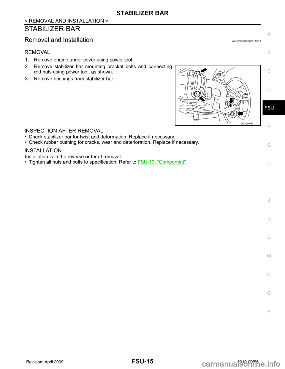
REMOVAL
1. Remove engine under cover using power tool.
2. Remove stabilizer bar mounting bracket bolts and connecting rod nuts using power tool, as shown.
3. Remove bushings from stabilizer bar.
INSPECTION AFTER REMOVAL
• Check stabilizer bar for twist and deformation. Replace if necessary.
• Check rubber bushing for cracks, wear and deterioration. Replace if necessary.
INSTALLATION
Installation is in the reverse order of removal.
• Tighten all nuts and bolts to specification. Refer to FSU-13, "
Component" .
LEIA0094E
Revision: April 20092010 QX56