engine INFINITI QX56 2010 Factory Service Manual
[x] Cancel search | Manufacturer: INFINITI, Model Year: 2010, Model line: QX56, Model: INFINITI QX56 2010Pages: 4210, PDF Size: 81.91 MB
Page 1976 of 4210

EXHAUST SYSTEMEX-7
< ON-VEHICLE REPAIR >
C
DE
F
G H
I
J
K L
M A
EX
NP
O
• Before installing a new heated o
xygen sensor, clean and lube the exhaust tube threads using suit-
able tool.
• Discard any heated oxygen sensor which has been dr opped from a height of more than 0.5 m (19.7
in) onto a hard surface such as a co ncrete floor; replace with a new one.
• Do not over-tighten the heated oxygen sensor. Doing so may damage the heated oxygen sensor, resulting in the MIL coming on.
• If any mounting insulator is badly deformed, repair or replace it. If deposits such as mud pile up on
the mounting insulators, clean and inspect them.
• Temporarily tighten the nuts on the exhaust manifold side and th e bolts on the vehicle side. Check
each part for interference with other components, an d then tighten the nuts and bolts to specifica-
tion.
INSPECTION AFTER INSTALLATION
• With the engine running, check exhaust tube joints for gas leakage and unusual noises.
• Check to ensure that mounting brackets and mount ing rubbers are installed properly and free from undue
stress. Improper installation could resu lt in excessive noise and vibration.
Oxygen sensor thread cleaner : — (J-43897-18)
Oxygen sensor thread cleaner : — (J-43897-12)
Revision: April 20092010 QX56
Page 1977 of 4210

EXL-1
DRIVER CONTROLS
C
DE
F
G H
I
J
K
M
SECTION EXL
A
B
EXL
N
O P
CONTENTS
EXTERIOR LIGHTING SYSTEM
BASIC INSPECTION ....... .............................4
DIAGNOSIS AND REPAIR WORKFLOW ..... .....4
Work Flow ........................................................... ......4
FUNCTION DIAGNOSIS ...............................7
HEADLAMP .................................................... .....7
System Diagram .................................................. ......7
System Description ...................................................7
Component Parts Location ........................................7
Component Description .............................................7
DAYTIME LIGHT SYSTEM .................................9
System Diagram .................................................. ......9
System Description ...................................................9
Component Parts Location ........................................9
Component Description ...........................................10
AUTO LIGHT SYSTEM ......................................11
System Diagram ......................................................11
System Description .................................................11
Component Parts Location ......................................12
Component Description ...........................................12
HEADLAMP AIMING SYSTEM (MANUAL) .......13
System Diagram .................................................. ....13
System Description .................................................13
Component Parts Location ......................................13
Component Description ...........................................13
FRONT FOG LAMP ............................................14
System Diagram .................................................. ....14
System Description .................................................14
Component Parts Location ......................................14
Component Description ...........................................14
TURN SIGNAL AND HAZARD WARNING
LAMPS ...............................................................
15
System Diagram .................................................. ....15
System Description .................................................15
Component Parts Location ......................................15
Component Description ....................................... ....16
PARKING, LICENSE PLATE AND TAIL
LAMPS ..............................................................
17
System Diagram ......................................................17
System Description ..................................................17
Component Parts Location ......................................17
Component Description ...........................................18
DIAGNOSIS SYSTEM (BCM) ...........................19
HEADLAMP ........................................................... ....19
HEADLAMP : CONSULT-III Function (BCM -
HEAD LAMP) ...........................................................
19
FLASHER ............................................................... ....20
FLASHER : CONSULT-III Function (BCM -
FLASHER) ...............................................................
20
COMB SW .............................................................. ....20
COMB SW : CONSULT-III Function (BCM -
COMB SW) ..............................................................
20
DIAGNOSIS SYSTEM (IPDM E/R) ...................22
Diagnosis Description ..............................................22
CONSULT - III Function (IPDM E/R) .......................24
COMPONENT DIAGNOSIS .........................27
POWER SUPPLY AND GROUND CIRCUIT ....27
BCM (BODY CONTROL MODULE) ...................... ....27
BCM (BODY CONTROL MODULE) : Diagnosis
Procedure ............................................................ ....
27
IPDM E/R (INTELLIGENT POWER DISTRIBU-
TION MODULE ENGINE ROOM) .......................... ....
28
IPDM E/R (INTELLIGENT POWER DISTRIBU-
TION MODULE ENGINE ROOM) : Diagnosis Pro-
cedure .................................................................. ....
28
HEADLAMP (HI) CIRCUIT ................................30
Description ...............................................................30
Revision: April 20092010 QX56
Page 1978 of 4210

EXL-2
Component Function Check ...................................30
Diagnosis Procedure - Without Daytime Light Sys-
tem ..........................................................................
30
Diagnosis Procedure - With Daytime Light System
...
31
HEADLAMP (LO) CIRCUIT ...............................33
Description ........................................................... ...33
Component Function Check ...................................33
Diagnosis Procedure - Without Daytime Light Sys-
tem ..........................................................................
33
Diagnosis Procedure - With Daytime Light System
...
34
FRONT FOG LAMP CIRCUIT ...........................36
Description ........................................................... ...36
Component Function Check ...................................36
Diagnosis Procedure ..............................................36
PARKING LAMP CIRCUIT ................................38
Description ........................................................... ...38
Component Function Check ...................................38
Diagnosis Procedure - Without Daytime Light Sys-
tem ..........................................................................
38
Diagnosis Procedure - With Daytime Light System
...
41
TURN SIGNAL LAMP CIRCUIT ........................44
Description ........................................................... ...44
Component Function Check ...................................44
Diagnosis Procedure ..............................................44
OPTICAL SENSOR ...........................................47
Description ..............................................................47
Component Function Check ...................................47
Diagnosis Procedure ..............................................47
HEADLAMP AIMING SWITCH ..........................49
Description ........................................................... ...49
Diagnosis Procedure - Without Daytime Light Sys-
tem ..........................................................................
49
Diagnosis Procedure - With Daytime Light System
...
50
HEADLAMP .......................................................52
Wiring Diagram .................................................... ...52
DAYTIME LIGHT SYSTEM ................................56
Wiring Diagram .................................................... ...56
AUTO LIGHT SYSTEM ......................................62
Wiring Diagram .................................................... ...62
HEADLAMP AIMING SYSTEM (MANUAL) ......69
Wiring Diagram .................................................... ...69
FRONT FOG LAMP SYSTEM ...........................73
Wiring Diagram .................................................... ...73
TURN SIGNAL AND HAZARD WARNING
LAMP SYSTEM .............................................. ...
77
Wiring Diagram .................................................... ...77
PARKING, LICENSE PLATE AND TAIL
LAMPS SYSTEM ...............................................
84
Wiring Diagram .................................................... ...84
STOP LAMP ......................................................91
Wiring Diagram .................................................... ...91
BACK-UP LAMP ............................................ ...95
Wiring Diagram .................................................... ...95
TRAILER TOW .................................................100
Wiring Diagram .....................................................100
ECU DIAGNOSIS ......................................106
BCM (BODY CONTROL MODULE) ............... ..106
Reference Value .................................................. .106
Terminal Layout ....................................................109
Physical Values .....................................................109
Wiring Diagram .....................................................115
Fail Safe ...............................................................119
DTC Inspection Priority Chart .............................120
DTC Index ............................................................120
IPDM E/R (INTELLIGENT POWER DISTRI-
BUTION MODULE ENGINE ROOM) ................
122
Reference Value .................................................. .122
Terminal Layout ....................................................124
Physical Values .....................................................125
Wiring Diagram .....................................................130
Fail Safe ...............................................................133
DTC Index ............................................................135
SYMPTOM DIAGNOSIS ...........................136
EXTERIOR LIGHTING SYSTEM SYMPTOMS ..136
Symptom Table .................................................... .136
NORMAL OPERATING CONDITION ...............138
Description ........................................................... .138
BOTH SIDE HEADLAMPS DO NOT SWITCH
TO HIGH BEAM ................................................
139
Description ........................................................... .139
Diagnosis Procedure .............................................139
BOTH SIDE HEADLAMPS (LO) ARE NOT
TURNED ON .....................................................
140
Description ............................................................140
Diagnosis Procedure .............................................140
PARKING, LICENSE PLATE AND TAIL
LAMPS ARE NOT TURNED ON ......................
141
Description ........................................................... .141
Diagnosis Procedure .............................................141
BOTH SIDE FRONT FOG LAMPS ARE NOT
TURNED ON .....................................................
142
Description ............................................................142
Diagnosis Procedure .............................................142
Revision: April 20092010 QX56
Page 1983 of 4210

HEADLAMPEXL-7
< FUNCTION DIAGNOSIS >
C
DE
F
G H
I
J
K
M A
B
EXL
N
O P
FUNCTION DIAGNOSIS
HEADLAMP
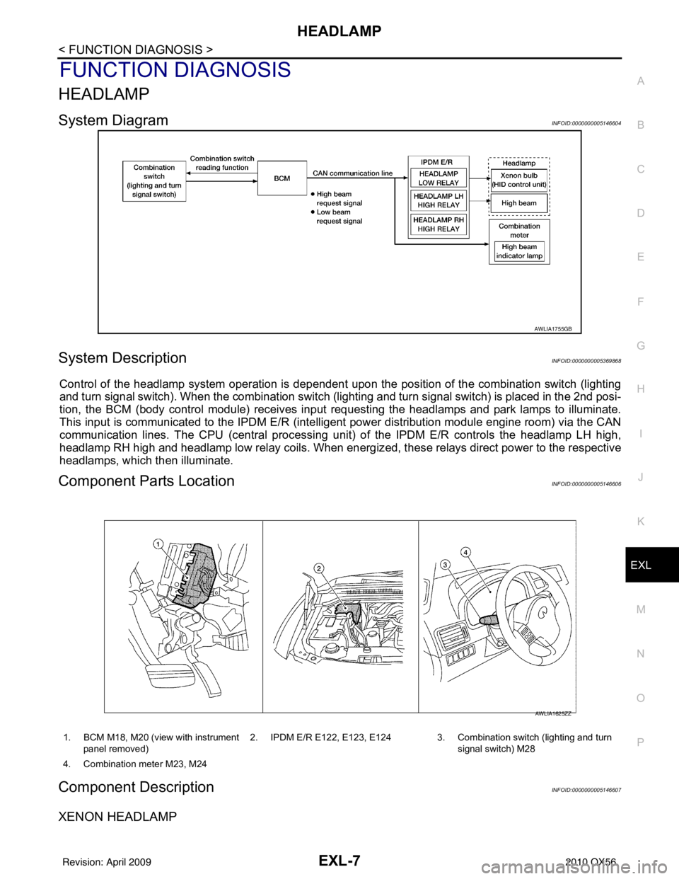
System DiagramINFOID:0000000005146604
System DescriptionINFOID:0000000005369868
Control of the headlamp system operation is dependent upon t he position of the combination switch (lighting
and turn signal switch). When the combination switch (lighting and turn signal switch) is placed in the 2nd posi-
tion, the BCM (body control module) receives input requesting the headlamps and park lamps to illuminate.
This input is communicated to the IPDM E/R (intelligent power distribution module engine room) via the CAN
communication lines. The CPU (central processing unit) of the IPDM E/R controls the headlamp LH high,
headlamp RH high and headlamp low relay coils. When energiz ed, these relays direct power to the respective
headlamps, which then illuminate.
Component Parts LocationINFOID:0000000005146606
Component DescriptionINFOID:0000000005146607
XENON HEADLAMP
AWLIA1755GB
1. BCM M18, M20 (view with instrument
panel removed) 2. IPDM E/R E122, E123, E124 3. Combination switch (lighting and turn
signal switch) M28
4. Combination meter M23, M24
AWLIA1625ZZ
Revision: April 20092010 QX56
Page 1985 of 4210

DAYTIME LIGHT SYSTEMEXL-9
< FUNCTION DIAGNOSIS >
C
DE
F
G H
I
J
K
M A
B
EXL
N
O P
DAYTIME LIGHT SYSTEM
System DiagramINFOID:0000000005369869
System DescriptionINFOID:0000000005146609
The headlamp system for Canada vehicles is equipped with a daytime light relay that activates the high beam
headlamps at approximately half illumination whenever the engine is operating. If the parking brake is applied
before the engine is started the daytime lights will not be illuminated. The daytime lights will illuminate once the
parking brake is released. Thereafter, the daytime lights will continue to operate when the parking brake is
applied.
Component Parts LocationINFOID:0000000005146610
AWLIA1751GB
AWLIA1626ZZ
Revision: April 20092010 QX56
Page 1986 of 4210

EXL-10
< FUNCTION DIAGNOSIS >
DAYTIME LIGHT SYSTEM
Component Description
INFOID:0000000005369870
After starting the engine with the parking brake releas ed and the combination switch (lighting and turn signal
switch) in the OFF or 1ST position, the headlamp high beam automatically turns on at a reduced intensity.
With the combination switch (lighting and turn signal switch) in the 2nd position or with autolamps ON, the
headlamps function the same as conventional light systems.
OPERATION
The BCM monitors inputs from the parking brake swit ch and the combination switch (lighting and turn signal
switch) to determine when to activate the daytime light system. The BCM sends a daytime light request to the
IPDM E/R via the CAN communication lines. The IPDM E/ R grounds the daytime light relay which in turn, pro-
vides power to the ground side of the LH high beam lamp. Power flows backward through the LH high beam
lamp to the IPDM E/R, through the high beam fuses, through the RH high beam lamp circuit to the RH high
beam lamp and on to ground. The high beam lamps are wired in series which causes them to illuminate at a
reduced intensity.
1. IPDM E/R E119, E122, E123, E124 2. BCM M18, M20 (view with instrument
panel removed)3. Daytime light relay E103
4. Combination switch (lighting and turn signal switch) M28 5. Combination meter M23, M24 6. Parking brake switch M11
Revision: April 20092010 QX56
Page 1987 of 4210

AUTO LIGHT SYSTEMEXL-11
< FUNCTION DIAGNOSIS >
C
DE
F
G H
I
J
K
M A
B
EXL
N
O P
AUTO LIGHT SYSTEM
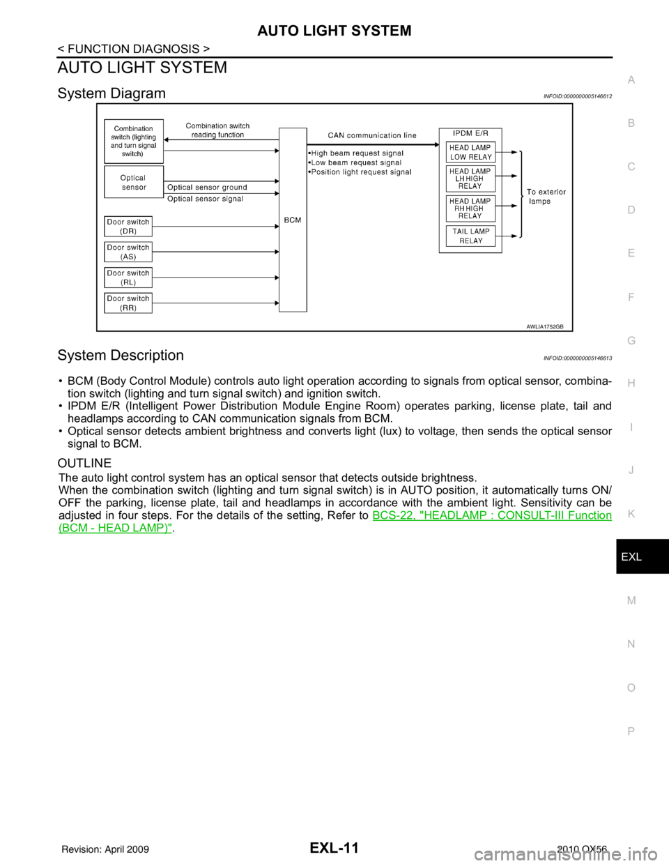
System DiagramINFOID:0000000005146612
System DescriptionINFOID:0000000005146613
• BCM (Body Control Module) controls auto light operati on according to signals from optical sensor, combina-
tion switch (lighting and turn signal switch) and ignition switch.
• IPDM E/R (Intelligent Power Distribution Module Engine Room) operates parking, license plate, tail and
headlamps according to CAN communication signals from BCM.
• Optical sensor detects ambient br ightness and converts light (lux) to voltage, then sends the optical sensor
signal to BCM.
OUTLINE
The auto light control system has an optical sensor that detects outside brightness.
When the combination switch (lighting and turn signal switch) is in AUTO position, it automatically turns ON/
OFF the parking, license plate, tail and headlamps in accordance with the ambient light. Sensitivity can be
adjusted in four steps. For the details of the setting, Refer to BCS-22, "
HEADLAMP : CONSULT-III Function
(BCM - HEAD LAMP)".
AWLIA1752GB
Revision: April 20092010 QX56
Page 1998 of 4210

EXL-22
< FUNCTION DIAGNOSIS >
DIAGNOSIS SYSTEM (IPDM E/R)
DIAGNOSIS SYSTEM (IPDM E/R)
Diagnosis DescriptionINFOID:0000000005369886
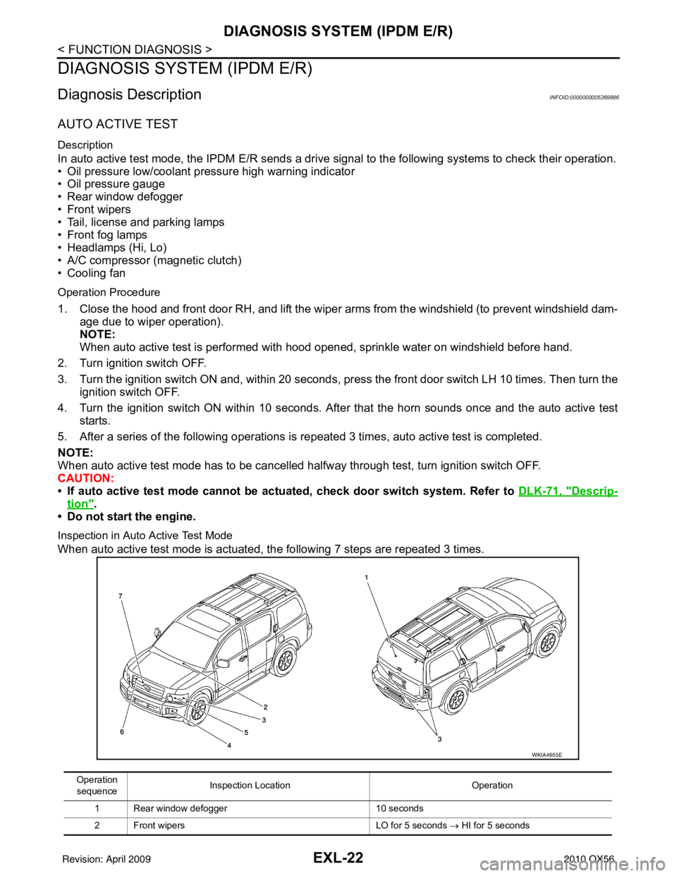
AUTO ACTIVE TEST
Description
In auto active test mode, the IPDM E/R sends a drive signal to the follo wing systems to check their operation.
• Oil pressure low/coolant pressure high warning indicator
• Oil pressure gauge
• Rear window defogger
• Front wipers
• Tail, license and parking lamps
• Front fog lamps
• Headlamps (Hi, Lo)
• A/C compressor (magnetic clutch)
• Cooling fan
Operation Procedure
1. Close the hood and front door RH, and lift the wiper a rms from the windshield (to prevent windshield dam-
age due to wiper operation).
NOTE:
When auto active test is performed with hood opened, sprinkle water on windshield before hand.
2. Turn ignition switch OFF.
3. Turn the ignition switch ON and, within 20 seconds, press the front door switch LH 10 times. Then turn the ignition switch OFF.
4. Turn the ignition switch ON within 10 seconds. Af ter that the horn sounds once and the auto active test
starts.
5. After a series of the following operations is repeated 3 times, auto active test is completed.
NOTE:
When auto active test mode has to be cancelled halfway through test, turn ignition switch OFF.
CAUTION:
• If auto active test mode cannot be actuated, check door switch system. Refer to DLK-71, "
Descrip-
tion".
• Do not start the engine.
Inspection in Auto Active Test Mode
When auto active test mode is actuated, the following 7 steps are repeated 3 times.
Operation
sequence Inspection Location
Operation
1 Rear window defogger 10 seconds
2 Front wipers LO for 5 seconds → HI for 5 seconds
WKIA4655E
Revision: April 20092010 QX56
Page 2004 of 4210

EXL-28
< COMPONENT DIAGNOSIS >
POWER SUPPLY AND GROUND CIRCUIT
Check continuity between BCM harness connector and ground.
Does continuity exist?
YES >> Inspection End.
NO >> Repair or replace harness.
IPDM E/R (INTELLIGENT POWER DISTRIBUTION MODULE ENGINE ROOM)
IPDM E/R (INTELLIGENT POWER DIST RIBUTION MODULE ENGINE ROOM) : Di-
agnosis Procedure
INFOID:0000000005369889
Regarding Wiring Diagram information, refer to PCS-27, "Wiring Diagram".
1. CHECK FUSES AND FUSIBLE LINK
Check that the following IPDM E/R fuses or fusible link are not blown.
Is the fuse blown?
YES >> Replace the blown fuse or fusible link after repairing the affected circuit.
NO >> GO TO 2
2. CHECK BATTERY POWER SUPPLY CIRCUIT
1. Turn ignition switch OFF.
2. Disconnect IPDM E/R.
3. Check voltage between IPDM E/R harness connectors and ground.
Is the measurement value normal?
YES >> GO TO 3
NO >> Repair or replace harness.
3. CHECK GROUND CIRCUIT
1. Turn ignition switch OFF.
BCM
GroundContinuity
Connector Terminal
M20 67 Yes
LIIA0915E
Terminal No. Signal nameFuses and fusible link No.
1 Battery A, D
2 Battery C
12 Ignition switch ON or START 59
TerminalsIgnition switch position
(+) (−) OFF ON START
Connector Terminal
E118 (A) 1
Ground Battery
voltage Battery
voltage Battery
voltage
2 Battery
voltage Battery
voltage Battery
voltage
E119 (B) 12 0VBattery
voltage Battery
voltage
AWMIA0023ZZ
Revision: April 20092010 QX56
Page 2006 of 4210

EXL-30
< COMPONENT DIAGNOSIS >
HEADLAMP (HI) CIRCUIT
HEADLAMP (HI) CIRCUIT
DescriptionINFOID:0000000005370270
The IPDM E/R (intelligent power distribution module engine room) controls the headlamp LH high and head-
lamp RH high relays based on inputs from the BCM via the CAN communication lines. When the headlamp LH
high and headlamp RH high relays are energized, power flows through fuse\
s 34 and 35, located in the IPDM
E/R. Power then flows to the front combination lamps to the headlamp high beam.
Component Function CheckINFOID:0000000005146640
1.CHECK HEADLAMP (HI) OPERATION
WITHOUT CONSULT-III
1. Start IPDM E/R auto active test. Refer to PCS-12, "
Diagnosis Description".
2. Check that the headlamp switches to the high beam. NOTE:
HI/LO is repeated 1 second each when usi ng the IPDM E/R auto active test.
CONSULT-III
1. Select "EXTERNAL LAMPS" of IPDM E/R active test item.
2. With the test item operating, check that the headlamp switches to high beam.
Does the headlamp switch to high beam?
YES >> Headlamp (HI) circuit is normal.
NO >> Refer to EXL-30, "
Diagnosis Procedure - Without Daytime Light System", EXL-31, "Diagnosis
Procedure - With Daytime Light System".
Diagnosis Procedure - Wit hout Daytime Light SystemINFOID:0000000005146641
Regarding Wiring Diagram information, refer to EXL-52, "Wiring Diagram".
1.CHECK HEADLAMP (HI) FUSES
1. Turn the ignition switch OFF.
2. Check that the following fuses are not open.
Is the fuse open?
YES >> Repair the harness and replace the fuse.
NO >> GO TO 2.
2.CHECK HEADLAMP (HI) OUTPUT VOLTAGE Hi : Headlamp switches to the high beam.
Off : Headlamp OFF
Unit
LocationFuse No.Capacity
Headlamp HI (LH) IPDM E/R3510A
Headlamp HI (RH) IPDM E/R3410A
Revision: April 20092010 QX56