upper INFINITI QX56 2010 Factory Service Manual
[x] Cancel search | Manufacturer: INFINITI, Model Year: 2010, Model line: QX56, Model: INFINITI QX56 2010Pages: 4210, PDF Size: 81.91 MB
Page 13 of 4210
ACCELERATOR CONTROL SYSTEMACC-5
< REMOVAL AND INSTALLATION >
C
DE
F
G H
I
J
K L
M A
ACC
NP
O
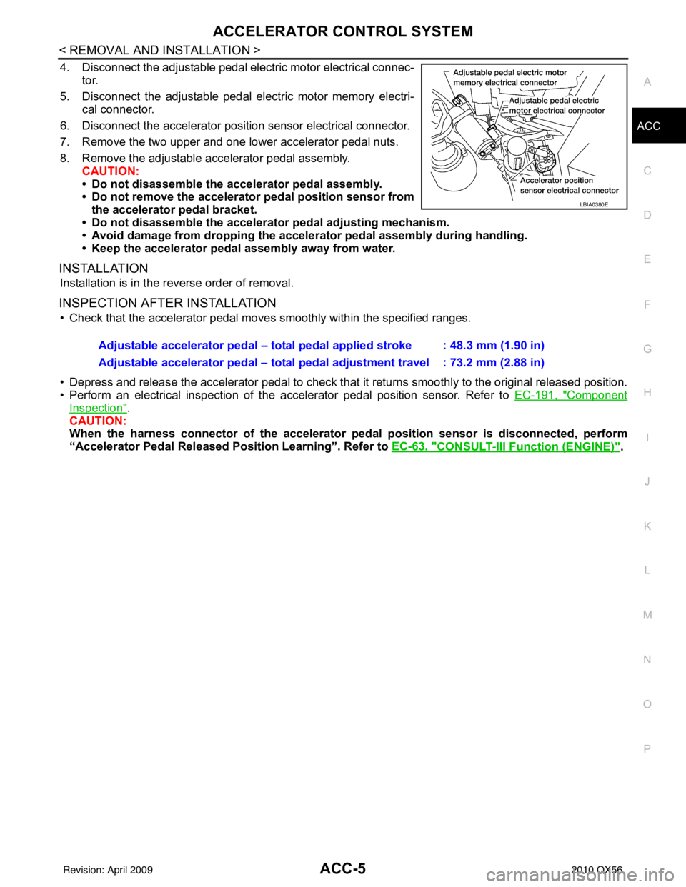
4. Disconnect the adjustable pedal electric motor electrical connec-
tor.
5. Disconnect the adjustable pedal electric motor memory electri- cal connector.
6. Disconnect the accelerator position sensor electrical connector.
7. Remove the two upper and one lower accelerator pedal nuts.
8. Remove the adjustable accelerator pedal assembly. CAUTION:
• Do not disassemble the accelerator pedal assembly.
• Do not remove the accelerator pedal position sensor fromthe accelerator pedal bracket.
• Do not disassemble the accelerator pedal adjusting mechanism.
• Avoid damage from dropping the acceler ator pedal assembly during handling.
• Keep the accelerator pedal assembly away from water.
INSTALLATION
Installation is in the reverse order of removal.
INSPECTION AFTER INSTALLATION
• Check that the accelerator pedal move s smoothly within the specified ranges.
• Depress and release the accelerator pedal to check that it returns smoothly to the original released position.
• Perform an electrical inspection of the accelerator pedal position sensor. Refer to EC-191, "
Component
Inspection".
CAUTION:
When the harness connector of the accelerator pedal position sensor is disco\
nnected, perform
“Accelerator Pedal Released Position Learning”. Refer to EC-63, "
CONSULT-III Function (ENGINE)".
LBIA0380E
Adjustable accelerator pedal – total pedal applied stroke : 48.3 mm (1.90 in)
Adjustable accelerator pedal – total pedal adjustment travel : 73.2 mm (2.88 in)
Revision: April 20092010 QX56
Page 231 of 4210
![INFINITI QX56 2010 Factory Service Manual AV-34
< FUNCTION DIAGNOSIS >[AUDIO SYSTEM]
DIAGNOSIS SYSTEM (AV CONTROL UNIT)
XM SAT SUBSCRIPTION STATUS
The XM NavTraffic subscription status can be checked.
Error History
The self-diagnosis result INFINITI QX56 2010 Factory Service Manual AV-34
< FUNCTION DIAGNOSIS >[AUDIO SYSTEM]
DIAGNOSIS SYSTEM (AV CONTROL UNIT)
XM SAT SUBSCRIPTION STATUS
The XM NavTraffic subscription status can be checked.
Error History
The self-diagnosis result](/img/42/57032/w960_57032-230.png)
AV-34
< FUNCTION DIAGNOSIS >[AUDIO SYSTEM]
DIAGNOSIS SYSTEM (AV CONTROL UNIT)
XM SAT SUBSCRIPTION STATUS
The XM NavTraffic subscription status can be checked.
Error History
The self-diagnosis results are judged depending on whether any
error occurs from when “Self-diagnosis” is selected until the self-
diagnosis results are displayed.
However, the diagnosis results are judged normal if an error has
occurred before the ignition SW is turned ON and then no error has
occurred until the self-diagnosis start. Check the “Error History” to
detect any error that may have occurred before the self-diagnosis
start because of this situation.
Count up method A
• The counter resets to 0 if an error occurs when IGN switch is
turned ON. The counter increases by 1 if thecondition is normal at
a next IGN ON cycle.
• The counter upper limit is 39. Any counts exceeding 39 are ignored. The counter can be reset (no error- record display) with the “Delete log” switch or CONSULT-III.
Count up method B
• The counter increases by 1 if an error occurs when IGN switch is ON. The counter will not decrease even
ifthe condition is normal at the next IGN ON cycle.
• The counter upper limit is 50. Any counts exceeding 50 are ignored. The counter can be reset (no error- record display) with the “Delete log” switch or CONSULT-III.
Error item
Some error items may be displayed simultaneously according to the cause. If some error items are displayed
simultaneously, the detection of the cause can be performed by the combination of display items
ALNIA0225GB
Display method of occur- rence frequency Error history diplay item
Count up method A CAN communication line, control unit (CAN), AV communication line, control unit (AV communica-
tion)
Count up method B Other than above
Error item DescriptionPossible malfunction factor/Action to take
CAN COMM CIRCUIT CAN communication malfunction is detect-
ed.Perform diagnosis with CONSULT-III, and
then repair the malfunctioning parts accord-
ing to the diagnosis results.
Refer to
AV- 3 8 , "
AV CONTROL UNIT :
CONSULT-III Function".
ALNIA0226GB
Revision: April 20092010 QX56
Page 233 of 4210
![INFINITI QX56 2010 Factory Service Manual AV-36
< FUNCTION DIAGNOSIS >[AUDIO SYSTEM]
DIAGNOSIS SYSTEM (AV CONTROL UNIT)
Vehicle CAN Diagnosis
• CAN communication status and error counter is displayed.
• The error counter displays “OK” INFINITI QX56 2010 Factory Service Manual AV-36
< FUNCTION DIAGNOSIS >[AUDIO SYSTEM]
DIAGNOSIS SYSTEM (AV CONTROL UNIT)
Vehicle CAN Diagnosis
• CAN communication status and error counter is displayed.
• The error counter displays “OK”](/img/42/57032/w960_57032-232.png)
AV-36
< FUNCTION DIAGNOSIS >[AUDIO SYSTEM]
DIAGNOSIS SYSTEM (AV CONTROL UNIT)
Vehicle CAN Diagnosis
• CAN communication status and error counter is displayed.
• The error counter displays “OK” if any malfunction was not
detected in the past and displays “0” if a malfunction is detected. It
increases by 1 if the condition is normal at the next ignition switch
ON cycle. The upper limit of the counter is 39.
• The error counter is erased if reset.
AV COMM Diagnosis
• AV communication status and error counter is displayed.
• The error counter displays “OK” if any malfunction was not detected in the past and displays “0” if a malfunction is detected. It
increases by 1 if the condition is normal at the next ignition switch
ON cycle. The upper limit of the counter is 39.
• The error counter is erased if reset.
Handsfree Phone
The hands-free phone reception volume adjustment, microphone
and speaker test, and memory erase functions are also available.
Bluetooth
Passkey confirmation/change
• AV COMM CIRCUIT
• Rear View Camera Connection Error • A malfunction is detected in camera con-
trol unit power supply and ground cir-
cuits.
• Malfunction is detected on AV communi- cation signal between camera control
unit and AV control unit. Rear view camera control unit power sup-
ply and ground circuits. Refer to
AV- 7 2 ,
"REAR VIEW CAMERA CONTROL UNIT :
Diagnosis Procedure".
• AV COMM CIRCUIT
• Rear View Camera Connection Error
• Rear View Camera Control Unit Connec-
tion Error • Malfunction is detected in AV communi-
cation circuit between camera control
unit and AV control unit.
• Malfunction is detected on AV communi- cation signal between camera control
unit and AV control unit. AV communication circuit between Camera
control unit and AV control unit.
Error item
DescriptionPossible malfunction factor/Action to take
ALNIA0227GB
ALNIA0265GB
ALNIA0228GB
Revision: April 20092010 QX56
Page 485 of 4210
BR-40
< DISASSEMBLY AND ASSEMBLY >
FRONT DISC BRAKE
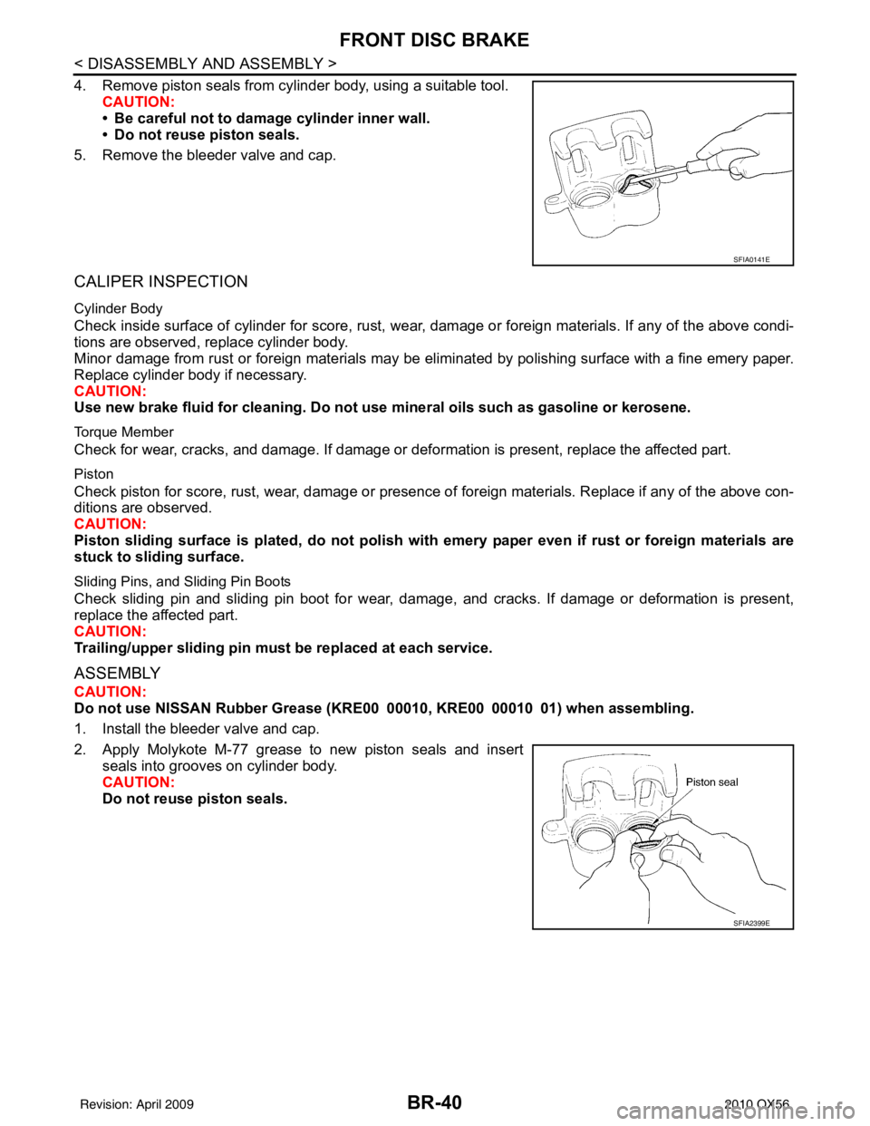
4. Remove piston seals from cylinder body, using a suitable tool.CAUTION:
• Be careful not to damage cylinder inner wall.
• Do not reuse piston seals.
5. Remove the bleeder valve and cap.
CALIPER INSPECTION
Cylinder Body
Check inside surface of cylinder for score, rust, wear, damage or foreign materials. If any of the above condi-
tions are observed, replace cylinder body.
Minor damage from rust or foreign materials may be el iminated by polishing surface with a fine emery paper.
Replace cylinder body if necessary.
CAUTION:
Use new brake fluid for cleaning. Do not use mineral oils such as gasoline or kerosene.
Torque Member
Check for wear, cracks, and damage. If damage or def ormation is present, replace the affected part.
Piston
Check piston for score, rust, wear, damage or presence of foreign materials. Replace if any of the above con-
ditions are observed.
CAUTION:
Piston sliding surface is plated, do not polish with emery paper even if rust or foreign materials are
stuck to sliding surface.
Sliding Pins, and Sliding Pin Boots
Check sliding pin and sliding pin boot for wear, damage, and cracks. If damage or deformation is present,
replace the affected part.
CAUTION:
Trailing/upper slidi ng pin must be replaced at each service.
ASSEMBLY
CAUTION:
Do not use NISSAN Rubber Grease ( KRE00 00010, KRE00 00010 01) when assembling.
1. Install the bleeder valve and cap.
2. Apply Molykote M-77 grease to new piston seals and insert seals into grooves on cylinder body.
CAUTION:
Do not reuse piston seals.
SFIA0141E
SFIA2399E
Revision: April 20092010 QX56
Page 620 of 4210
BODY REPAIRBRM-9
< SERVICE INFORMATION >
C
DE
F
G H
I
J
L
M A
B
BRM
N
O P
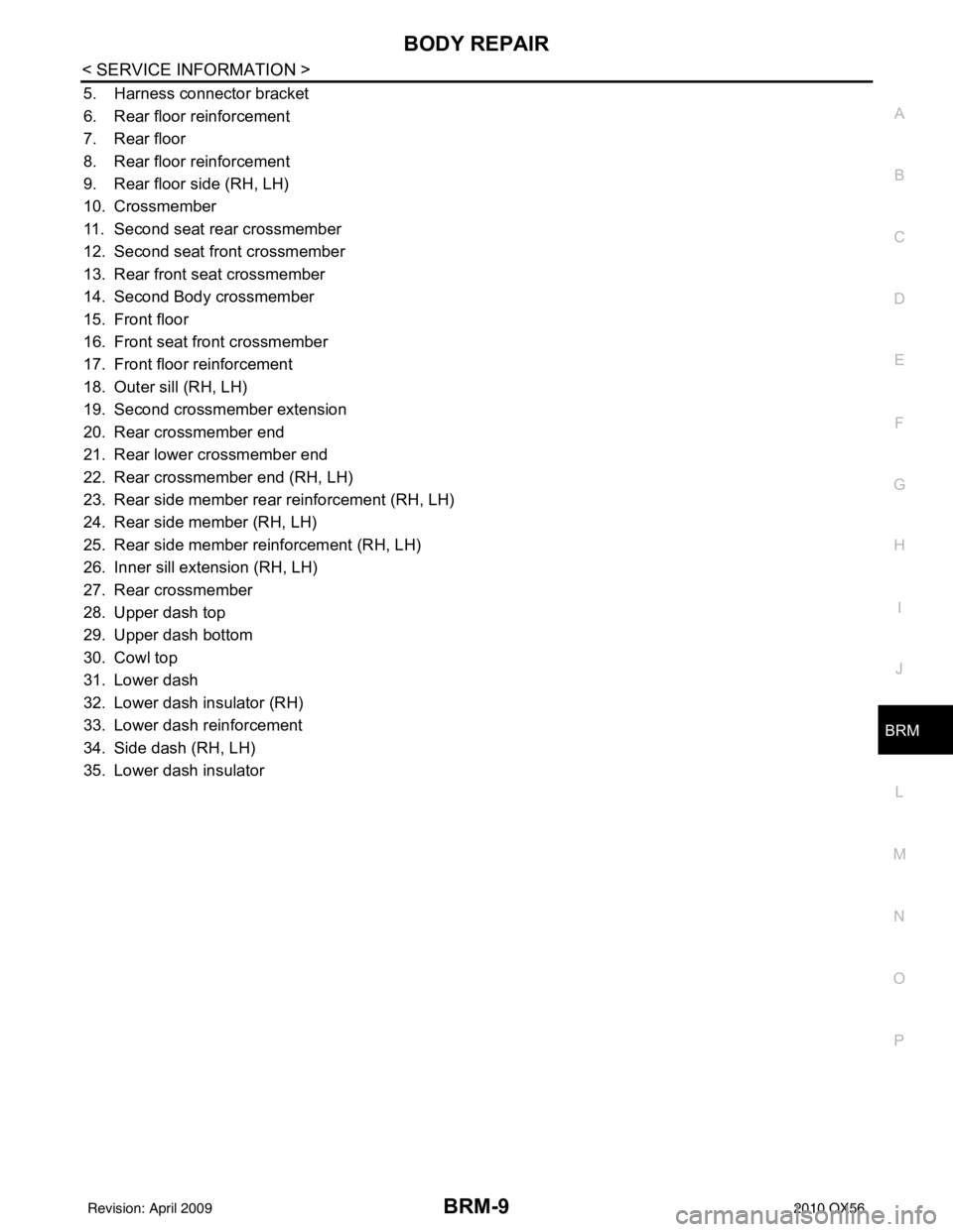
5. Harness connector bracket
6. Rear floor reinforcement
7. Rear floor
8. Rear floor reinforcement
9. Rear floor side (RH, LH)
10. Crossmember
11. Second seat rear crossmember
12. Second seat front crossmember
13. Rear front seat crossmember
14. Second Body crossmember
15. Front floor
16. Front seat front crossmember
17. Front floor reinforcement
18. Outer sill (RH, LH)
19. Second crossmember extension
20. Rear crossmember end
21. Rear lower crossmember end
22. Rear crossmember end (RH, LH)
23. Rear side member rear reinforcement (RH, LH)
24. Rear side member (RH, LH)
25. Rear side member reinforcement (RH, LH)
26. Inner sill extension (RH, LH)
27. Rear crossmember
28. Upper dash top
29. Upper dash bottom
30. Cowl top
31. Lower dash
32. Lower dash insulator (RH)
33. Lower dash reinforcement
34. Side dash (RH, LH)
35. Lower dash insulator
Revision: April 20092010 QX56
Page 622 of 4210
BODY REPAIRBRM-11
< SERVICE INFORMATION >
C
DE
F
G H
I
J
L
M A
B
BRM
N
O P
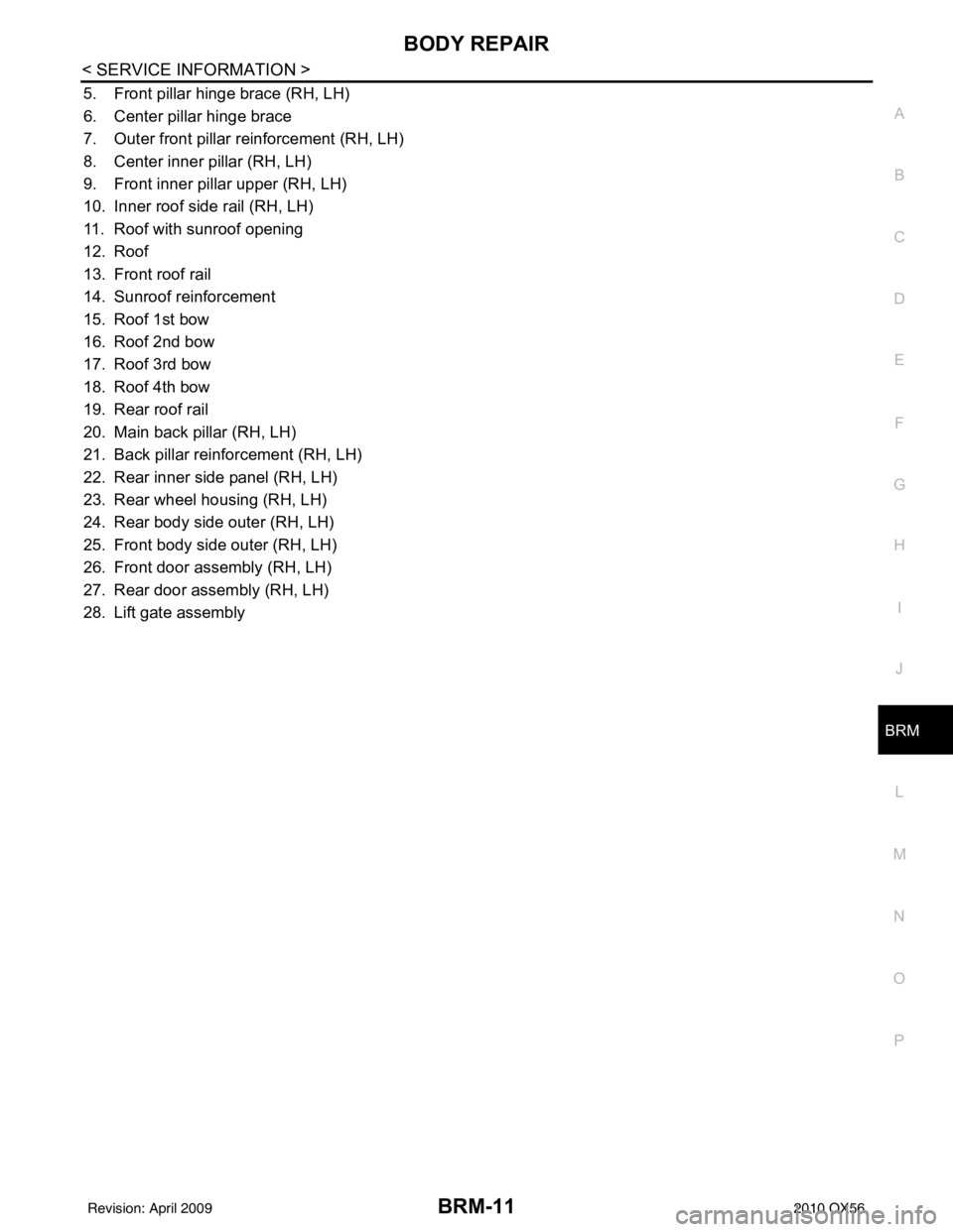
5. Front pillar hinge brace (RH, LH)
6. Center pillar hinge brace
7. Outer front pillar reinforcement (RH, LH)
8. Center inner pillar (RH, LH)
9. Front inner pillar upper (RH, LH)
10. Inner roof side rail (RH, LH)
11. Roof with sunroof opening
12. Roof
13. Front roof rail
14. Sunroof reinforcement
15. Roof 1st bow
16. Roof 2nd bow
17. Roof 3rd bow
18. Roof 4th bow
19. Rear roof rail
20. Main back pillar (RH, LH)
21. Back pillar reinforcement (RH, LH)
22. Rear inner side panel (RH, LH)
23. Rear wheel housing (RH, LH)
24. Rear body side outer (RH, LH)
25. Front body side outer (RH, LH)
26. Front door assembly (RH, LH)
27. Rear door assembly (RH, LH)
28. Lift gate assembly
Revision: April 20092010 QX56
Page 624 of 4210
BODY REPAIRBRM-13
< SERVICE INFORMATION >
C
DE
F
G H
I
J
L
M A
B
BRM
N
O P
6. 2nd crossmember assembly
7. Front upper link mounting bracket RH/LH
8. Panhard rod bracket reinforcement
9. Bound bumper bracket RH/LH
10. Front brake hose bracket RH/LH
11. Panhard rod reinforcement
12. 4th crossmember gusset RH/LH
13. 2nd cab mounting bracket RH/LH
14. 3rd cab mounting bracket RH/LH
15. 4th cab mounting reinforcement RH/LH
16. 4th cab mounting bracket RH/LH
17. Rear suspension mounting bracket RH/LH
18. Rear brake hose bracket
19. Rear shock absorber bracket assembly RH/LH
20. Rear bound bumper bracket RH/LH
21. Rear bracket bumper reinforcement RH/LH
22. Cab mounting bracket assembly RH/LH
23. 9th crossmember assembly
24. Exhaust bracket assembly
25. Canister bracket, LH
26. 7th crossmember reinforcement
27. 7th crossmember assembly
28. 6th crossmember assembly
29. 4th crossmember gusset RH/LH
30. 4th crossmember assembly
31. 3rd crossmember assembly
32. Frame assembly
Corrosion ProtectionINFOID:0000000005147334
DESCRIPTION
To provide improved corrosion prevention, the follo wing anti-corrosive measures have been implemented in
NISSAN production plants. When repairing or replacing body panels, it is necessary to use the same anti-cor-
rosive measures.
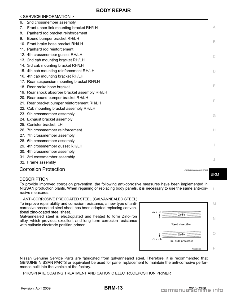
ANTI-CORROSIVE PRECOATED ST EEL (GALVANNEALED STEEL)
To improve repairability and corrosion resistance, a new type of anti-
corrosive precoated steel sheet has been adopted replacing conven-
tional zinc-coated steel sheet.
Galvannealed steel is electroplated and heated to form Zinc-iron
alloy, which provides excellent and long term corrosion resistance
with cationic electrode position primer.
Nissan Genuine Service Parts are fabricated from galvannealed steel. Therefore, it is recommended that
GENUINE NISSAN PARTS or equivalent be used for panel replacement to maintain the anti-corrosive perfor-
mance built into the vehicle at the factory.
PHOSPHATE COATING TREATMENT AND CA TIONIC ELECTRODEPOSITION PRIMER
PIIA0093E
Revision: April 20092010 QX56
Page 649 of 4210
BRM-38
< SERVICE INFORMATION >
BODY REPAIR
Precaution in Repairing High Strength Steel
INFOID:0000000005147339
High strength steel is used for body panels in order to reduce vehicle weight.
Accordingly, precautions in repairing automotive bodies made of high strength steel are described below:
High strength steel (hss) used in nissan vehicles
SP130 is the most commonly used HSS.
SP150 HSS is used only on parts that require much more strength.
Read the following precautions when repairing HSS:
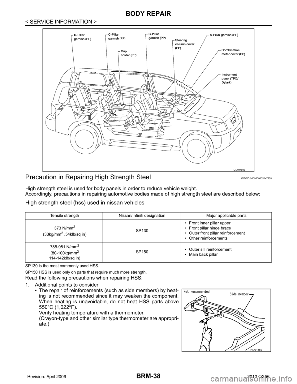
1. Additional points to consider • The repair of reinforcements (such as side members) by heat-ing is not recommended since it may weaken the component.
When heating is unavoidable, do not heat HSS parts above
550° C (1,022° F).
Verify heating temperature with a thermometer.
(Crayon-type and other similar type thermometer are appropri-
ate.)
LIIA1061E
Tensile strength Nissan/Infiniti designation Major applicable parts
373 N/mm
2
(38kg/mm2 ,54klb/sq in) SP130• Front inner pillar upper
• Front pillar hinge brace
• Outer front pillar reinforcement
• Other reinforcements
785-981 N/mm
2
(80-100kg/mm2
114-142klb/sq in) SP150
• Outer sill reinforcement
• Main back pillar
PIIA0115E
Revision: April 20092010 QX56
Page 763 of 4210
CHG
GENERATORCHG-21
< ON-VEHICLE REPAIR >
C
DE
F
G H
I
J
K L
B A
O P
N
ON-VEHICLE REPAIR
GENERATOR
Removal and InstallationINFOID:0000000005146567
REMOVAL
1. Disconnect the negative battery terminal. Refer to
PG-74, "Removal and Installation".
2. Remove the fan shroud. Refer to CO-15, "
Removal and Installation".
3. Remove the drive belt. Refer to EM-13, "
Removal and Installation".
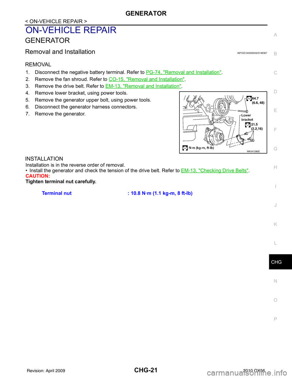
4. Remove lower bracket, using power tools.
5. Remove the generator upper bolt, using power tools.
6. Disconnect the generator harness connectors.
7. Remove the generator.
INSTALLATION
Installation is in the reverse order of removal.
• Install the generator and check the t ension of the drive belt. Refer to EM-13, "
Checking Drive Belts".
CAUTION:
Tighten terminal nut carefully.
WKIA1390E
Terminal nut : 10.8 N·m (1.1 kg-m, 8 ft-lb)
Revision: April 20092010 QX56
Page 779 of 4210
RADIATORCO-15
< ON-VEHICLE REPAIR >
C
DE
F
G H
I
J
K L
M A
CO
NP
O
ON-VEHICLE REPAIR
RADIATOR
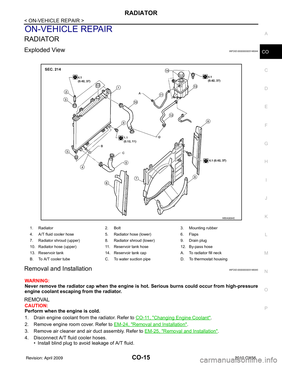
Exploded ViewINFOID:0000000005149044
Removal and InstallationINFOID:0000000005149045
WARNING:
Never remove the radiator cap when the engine is hot.
Serious burns could occur from high-pressure
engine coolant escaping from the radiator.
REMOVAL
CAUTION:
Perform when the engine is cold.
1. Drain engine coolant from the radiator. Refer to CO-11, "
Changing Engine Coolant".
2. Remove engine room cover. Refer to EM-24, "
Removal and Installation".
3. Remove air cleaner and air duct assembly. Refer to EM-25, "
Removal and Installation".
4. Disconnect A/T fluid cooler hoses. • Install blind plug to avoid leakage of A/T fluid.
1. Radiator 2. Bolt 3. Mounting rubber
4. A/T fluid cooler hose 5. Radiator hose (lower) 6. Flaps
7. Radiator shroud (upper) 8. Radiator shroud (lower) 9. Drain plug
10. Radiator hose (upper) 11. Reservoir tank hose 12. By-pass hose
13. Reservoir tank 14. Reservoir tank cap A. To radiator fill neck
B. To A/T cooler tube C. To water suction pipe D. To thermostat housing
WBIA0694E
Revision: April 20092010 QX56