relay INFINITI QX56 2011 Factory Service Manual
[x] Cancel search | Manufacturer: INFINITI, Model Year: 2011, Model line: QX56, Model: INFINITI QX56 2011Pages: 5598, PDF Size: 94.53 MB
Page 1524 of 5598

DEF-32
< DTC/CIRCUIT DIAGNOSIS >
WIPER DEICER RELAY
WIPER DEICER RELAY
Component Function CheckINFOID:0000000006299451
1.CHECK WIPER DEICER RELAY POWER SUPPLY CIRCUIT
1. Select Active Test (“REAR DEFOGGER”) mode of “BCM” using CONSULT-III.
2. Touch “ON”.
3. Check that the front window heating wire is getting warmer.
Is the inspection result normal?
YES >> Wiper deicer relay power supply circuit function is OK.
NO >> Refer to DEF-32, "
Diagnosis Procedure".
Diagnosis ProcedureINFOID:0000000006299452
1.CHECK WIPER DEICER CIRCUIT 1
1. Turn ignition switch ON.
2. Check voltage between wiper deicer relay harness connector and ground.
Is the inspection result normal?
YES >> GO TO 3.
NO >> GO TO 2.
2.CHECK WIPER DEICER CIRCUIT 2
1. Turn ignition switch OFF.
2. Disconnect wiper deicer relay and IPDM E/R connector.
3. Check continuity between wiper deicer relay terminal connector and IPDM E/R harness connector.
Is the inspection result normal?
YES >> GO TO 6.
NO >> Repair or replace harness.
3.CHECK WIPER DEICER CIRCUIT 3
Check voltage between wiper deicer relay harness connector and ground.
Is the inspection result normal?
YES >> GO TO 4.
NO >> Repair or replace harness.
4.CHECK WIPER DEICER RELAY GROUND CIRCUIT
1. Turn ignition switch OFF.
2. Disconnect wiper deicer relay connector.
3. Check continuity between wiper deicer relay terminal connector and ground.
(+)
(–) Condition Voltage (V)
(Approx.)
Wiper deicer relay
Connector Terminal
E23 1 Ground Rear window defogger switch: ON Battery voltage
Rear window defogger switch: OFF 0
Wiper deicer relay IPDM E/R
Continuity
Connector Terminal Connector Terminal
E23 1 E11 14 Existed
(+) (–)Voltage (V)
(Approx.)
Wiper deicer relay
Connector Terminal E23 3 Ground Battery voltage
Revision: 2010 May2011 QX56
Page 1525 of 5598

WIPER DEICER RELAYDEF-33
< DTC/CIRCUIT DIAGNOSIS >
C
DE
F
G H
I
J
K
M A
B
DEF
N
O P
Is the inspection result normal?
YES >> GO TO 5.
NO >> Repair or replace harness.
5.CHECK WIPER DEICER RELAY
Check wiper deicer relay.
Refer to DEF-33, "
Component Inspection".
Is the inspection result normal?
YES >> GO TO 6.
NO >> Replace wiper deicer relay.
6.CHECK INTERMITTENT INCIDENT
Check intermittent incident.
Refer to GI-40, "
Intermittent Incident".
>> INSPECTION END
Component InspectionINFOID:0000000006299453
1.CHECK WIPER DEICER RELAY
1. Turn ignition switch OFF.
2. Disconnect wiper deicer relay.
3. Check wiper deicer relay.
Is the inspection result normal?
YES >> INSPECTION END
NO >> Replace wiper deicer relay.
Wiper deicer relay
GroundContinuity
Connector Terminal
E23 2 Existed
Wiper deicer relay Condition Continuity
Te r m i n a l
35 12 V direct current supply between termi-
nals 1 and 2
Existed
No current supply Not existed
SEF497Y
Revision: 2010 May2011 QX56
Page 1526 of 5598

DEF-34
< DTC/CIRCUIT DIAGNOSIS >
WIPER DEICER
WIPER DEICER
Component Function CheckINFOID:0000000006299454
1.CHECK WIPER DEICER
1. Select Active Test (“REAR DEFOGGER”) mode of “BCM” using CONSULT-III.
2. Touch “ON”.
3. Check that the front window heating wire is getting warmer.
Is the inspection result normal?
YES >> Wiper deicer is OK.
NO >> Refer to DEF-34, "
Diagnosis Procedure"
Diagnosis ProcedureINFOID:0000000006299455
1.CHECK FUSE
1. Turn ignition switch OFF.
2. Check 15 A fuse [No.75, located in fuse block (J/B)]
Is the inspection result normal?
YES >> GO TO 2.
NO >> Replace the blown fuse after repairing the affected circuit if a fuse is blown.
2.CHECK POWER SUPPLY CIRCUIT
1. Turn ignition switch ON.
2. Check voltage between wiper deicer harness connector and ground.
Is the inspection result normal?
YES >> GO TO 3.
NO >> GO TO 4.
3.CHECK GROUND CIRCUIT
1. Turn ignition switch OFF.
2. Disconnect wiper deicer connector.
3. Check continuity between wiper deicer harness connector and ground.
Is the inspection result normal?
YES >> GO TO 5.
NO >> Repair or replace harness between rear window defogger and ground.
4.CHECK WIPER DEICER CIRCUIT
1. Turn ignition switch OFF.
2. Disconnect wiper deicer relay connector and wiper deicer connector.
3. Check continuity between wiper deicer relay harness connector and wiper deicer harness connector.
(+)
(–) Condition Voltage (V)
(Approx.)
Wiper deicer
Connector Terminal
E40 1 Ground Rear window defogger switch: ON Battery voltage
Rear window defogger switch: OFF 0
Wiper deicer
GroundContinuity
Connector Terminal
E40 2 Existed
Revision: 2010 May2011 QX56
Page 1527 of 5598

WIPER DEICERDEF-35
< DTC/CIRCUIT DIAGNOSIS >
C
DE
F
G H
I
J
K
M A
B
DEF
N
O P
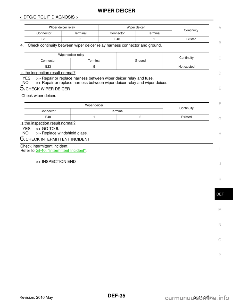
4. Check continuity between wiper deicer relay harness connector and ground.
Is the inspection result normal?
YES >> Repair or replace harness between wiper deicer relay and fuse.
NO >> Repair or replace harness between wiper deicer relay and wiper deicer.
5.CHECK WIPER DEICER
Check wiper deicer.
Is the inspection result normal?
YES >> GO TO 6.
NO >> Replace windshield glass.
6.CHECK INTERMITTENT INCIDENT
Check intermittent incident.
Refer to GI-40, "
Intermittent Incident".
>> INSPECTION END
Wiper deicer relay Wiper deicer Continuity
Connector Terminal Connector Terminal
E235E401Existed
Wiper deicer relay GroundContinuity
Connector Terminal
E23 5 Not existed
Wiper deicer Continuity
Connector Terminal
E40 1 2 Existed
Revision: 2010 May2011 QX56
Page 1528 of 5598

DEF-36
< SYMPTOM DIAGNOSIS >
REAR WINDOW DEFOGGER DOES NOT OPERATE
SYMPTOM DIAGNOSIS
REAR WINDOW DEFOGGER DOES NOT OPERATE
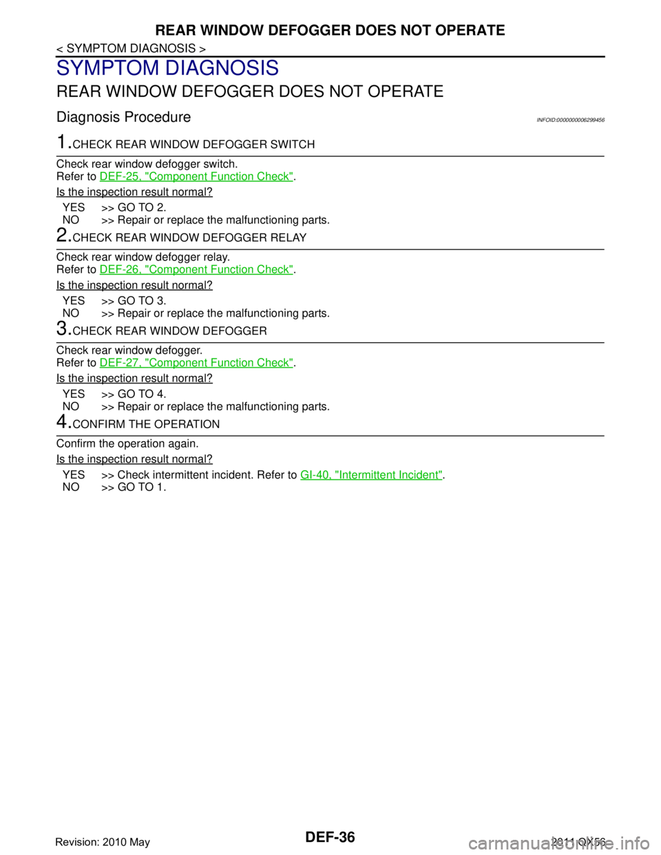
Diagnosis ProcedureINFOID:0000000006299456
1.CHECK REAR WINDOW DEFOGGER SWITCH
Check rear window defogger switch.
Refer to DEF-25, "
Component Function Check".
Is the inspection result normal?
YES >> GO TO 2.
NO >> Repair or replace the malfunctioning parts.
2.CHECK REAR WINDOW DEFOGGER RELAY
Check rear window defogger relay.
Refer to DEF-26, "
Component Function Check".
Is the inspection result normal?
YES >> GO TO 3.
NO >> Repair or replace the malfunctioning parts.
3.CHECK REAR WINDOW DEFOGGER
Check rear window defogger.
Refer to DEF-27, "
Component Function Check".
Is the inspection result normal?
YES >> GO TO 4.
NO >> Repair or replace the malfunctioning parts.
4.CONFIRM THE OPERATION
Confirm the operation again.
Is the inspection result normal?
YES >> Check intermittent incident. Refer to GI-40, "Intermittent Incident".
NO >> GO TO 1.
Revision: 2010 May2011 QX56
Page 1529 of 5598

REAR WINDOW DEFOGGER AND DOOR MIRROR DEFOGGER DO NOT OPER-
ATE.
DEF-37
< SYMPTOM DIAGNOSIS >
C
D E
F
G H
I
J
K
M A
B
DEF
N
O P
REAR WINDOW DEFOGGER AND DO OR MIRROR DEFOGGER DO NOT
OPERATE.
Diagnosis ProcedureINFOID:0000000006299457
1.CHECK REAR WINDOW DEFOGGER SWITCH
Check rear window defogger switch.
Refer to DEF-25, "
Component Function Check".
Is the inspection result normal?
YES >> GO TO 2.
NO >> Repair or replace the malfunctioning parts.
2.CHECK REAR WINDOW DEFOGGER RELAY
Check rear window defogger relay.
Refer to DEF-26, "
Component Function Check".
Is the inspection result normal?
YES >> GO TO 3.
NO >> Repair or replace the malfunctioning parts.
3.CHECK REAR WINDOW DEFOGGER
Check rear window defogger.
Refer to DEF-27, "
Component Function Check".
Is the inspection result normal?
YES >> GO TO 4.
NO >> Repair or replace the malfunctioning parts.
4.CONFIRM THE OPERATION
Confirm the operation again.
Is the inspection result normal?
YES >> Check intermittent incident. Refer to GI-40, "Intermittent Incident".
NO >> GO TO 1.
Revision: 2010 May2011 QX56
Page 1533 of 5598

WIPER DEICER DOSE NOT OPERATEDEF-41
< SYMPTOM DIAGNOSIS >
C
DE
F
G H
I
J
K
M A
B
DEF
N
O P
WIPER DEICER DOSE NOT OPERATE
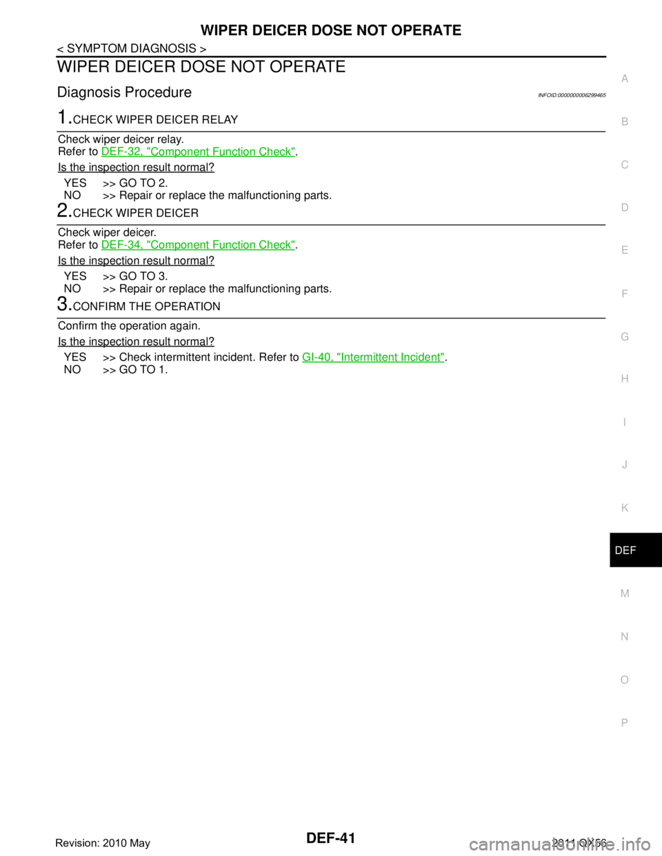
Diagnosis ProcedureINFOID:0000000006299465
1.CHECK WIPER DEICER RELAY
Check wiper deicer relay.
Refer to DEF-32, "
Component Function Check".
Is the inspection result normal?
YES >> GO TO 2.
NO >> Repair or replace the malfunctioning parts.
2.CHECK WIPER DEICER
Check wiper deicer.
Refer to DEF-34, "
Component Function Check".
Is the inspection result normal?
YES >> GO TO 3.
NO >> Repair or replace the malfunctioning parts.
3.CONFIRM THE OPERATION
Confirm the operation again.
Is the inspection result normal?
YES >> Check intermittent incident. Refer to GI-40, "Intermittent Incident".
NO >> GO TO 1.
Revision: 2010 May2011 QX56
Page 1578 of 5598

DLK-42
< SYSTEM DESCRIPTION >
DIAGNOSIS SYSTEM (BCM)
SELF-DIAG RESULT
Refer to BCS-57, "DTCIndex".
DATA MONITOR
AUTO LOCK SET Auto door lock operation time can be changed in this mode
MODE 1: OFF
MODE 2: 30 sec
MODE 3: 1 minute
MODE 4: 2 minutes
MODE 5: 3 minutes
MODE 6: 4 minutes
MODE 7: 5 minutes
HORN WITH KEYLESS LOCK Horn reminder function mode by Intelligent Key button can be selected from the following with
this mode
On: Operate
Off: Non-operation
PW DOWN SET Unlock button pressing time on Intelligent Key button can be selected from the following with
this mode
MODE 1: 3 sec
MODE 2: Non-operation
MODE 3: 5 sec
WELCOME LIGHT SELECT Welcome light function mode can be selected from the following with this mode
Puddle/Outside Handle
Room lamp
Head & Tail Lamps (this item is displayed, but cannot be used)
Heart Beat
WELCOME LIGHT OP SET Welcome light function mode can be changed to operation with this mode
On: Operate
Off: Non-operation
Monitor item Description
Monitor Item Condition
REQ SW -DR Indicates [On/Off] condition of door request switch (driver side)
REQ SW -AS Indicates [On/Off] condition of door request switch (passenger side)
REQ SW -BD/TR Indicates [On/Off] condition of back door request switch
PUSH SW Indicates [On/Off] condition of push-button ignition switch
CLUTCH SW NOTE:
This item is displayed, but cannot be monitored
BRAKE SW 1 Indicates [On/Off]* condition of stop lamp switch power supply
BRAKE SW 2 Indicates [On/Off] condition of stop lamp switch
DETE/CANCL SW Indicates [On/Off] condition of P position
SFT PN/N SW Indicates [On/Off] condition of P or N position
S/L -LOCK Indicates [On/Off] condition of steering lock unit (LOCK)
S/L -UNLOCK Indicates [On/Off] condition of steering lock unit (UNLOCK)
S/L RELAY -F/B Indicates [On/Off] condition of steering lock relay
UNLK SEN -DR Indicates [On/Off] condition of driver door UNLOCK status
PUSH SW -IPDM Indicates [On/Off] condition of push-button ignition switch
IGN RLY1 -F/B Indicates [On/Off] condition of ignition relay 1
DETE SW -IPDM Indicates [On/Off] condition of P position
SFT PN -IPDM Indicates [On/Off] condition of P or N position
SFT P -MET Indicates [On/Off] condition of P position
SFT N -MET Indicates [On/Off] condition of N position
ENGINE STATE Indicates [Stop/Stall/Crank/Run] condition of engine states
Revision: 2010 May2011 QX56
Page 1579 of 5598

DIAGNOSIS SYSTEM (BCM)DLK-43
< SYSTEM DESCRIPTION >
C
DE
F
G H
I
J
L
M A
B
DLK
N
O P
*: OFF is displayed when brake pedal is depressed while brake switch power supply is OFF.
ACTIVE TEST
S/L LOCK-IPDM Indicates [On/Off] condition of steering lock unit (LOCK)
S/L UNLK-IPDM Indicates [On/Off] condition of steering lock unit (UNLOCK)
S/L RELAY-REQ Indicates [On/Off] condition of steering lock relay
VEH SPEED 1 Display the vehicle speed signal received from combination meter by numerical value [Km/h]
VEH SPEED 2 Display the vehicle spee d signal received from ABS or VDC or TCM by numerical value [Km/h]
DOOR STAT-DR Indicates [LOCK/READY/UNLK] condition of unlock sensor
DOOR STAT-AS Indicates [LOCK/READY/UNLK] condition of passenger side door status
ID OK FLAG Indicates [Set/Reset] condition of key ID
PRMT ENG STRT Indicates [Set/Reset] condition of engine start possibility
PRMT RKE STRT NOTE:
This item is displayed, but cannot be monitored
TRNK/HAT MNTR NOTE:
This item is displayed, but cannot be monitored
RKE-LOCK Indicates [On/Off] condition of LOCK signal from Intelligent Key
RKE-UNLOCK Indicates [On/Off] condition of UNLOCK signal from Intelligent Key
RKE-TR/BD NOTE:
This item is displayed, but cannot be monitored
RKE-PANIC Indicates [On/Off] condition of PANIC button of Intelligent Key
RKE-MODE CHG Indicates [On/Off] condition of MODE CHANGE signal from Intelligent Key
RKE OPE COUN1 When remote keyless entry receiver receives the signal transmitted while operating on Intelli-
gent Key, the numerical value start changing
RKE OPE COUN2 NOTE:
This item is displayed, but cannot be monitored
Monitor Item Condition
Test item Description
BATTERY SAVER This test is able to check interior room lamp operation
On: Operate
Off: Non-operation
OUTSIDE BUZZER This test is able to check Intelligent Key warning buzzer operation
On: Operate
Off: Non-operation
INSIDE BUZZER This test is able to check warning chime in combination meter operation
Take Out: Take away warning chime sounds when CONSULT-III screen is touched
Key: Key warning chime sounds when CONSULT-III screen is touched
Knob: OFF position warning chime sounds when CONSULT-III screen is touched
Off: Non-operation
INDICATOR This test is able to check warning lamp operation
KEY ON: “KEY” Warning lamp illuminates when CONSULT-III screen is touched
KEY IND: “KEY” Warning lamp blinks when CONSULT-III screen is touched
Off: Non-operation
INT LAMP This test is able to check interior room lamp operation
On: Operate
Off: Non-operation
Revision: 2010 May2011 QX56
Page 2025 of 5598

EC-1
ENGINE
C
DE
F
G H
I
J
K L
M
SECTION EC
A
EC
N
O P
CONTENTS
ENGINE CONTROL SYSTEM
VK56VD
PRECAUTION ................ ...............................
9
PRECAUTIONS .............................................. .....9
Precaution for Supplemental Restraint System
(SRS) "AIR BAG" and "SEAT BELT PRE-TEN-
SIONER" ............................................................. ......
9
Precaution for Procedure without Cowl Top Cover ......9
Precautions For Xenon Headlamp Service ...............9
On Board Diagnostic (OBD) System of Engine
and A/T ....................................................................
10
General Precautions ...............................................10
PREPARATION ...........................................14
PREPARATION .............................................. ....14
Special Service Tools .......................................... ....14
Commercial Service Tools ......................................14
SYSTEM DESCRIPTION .............................16
COMPONENT PARTS ................................... ....16
Component Parts Location .................................. ....16
Component Description ...........................................19
Accelerator Pedal Position Sensor ..........................21
Air Fuel Ratio (A/F) Sensor 1 ..................................21
ASCD Brake Switch & Stop Lamp Switch ...............21
ASCD Steering Switch ............................................21
ASCD Indicators ......................................................21
Battery Current Sensor (With Battery Tempera-
ture Sensor) ............................................................
22
Camshaft Position Sensor .......................................22
Crankshaft Position Sensor .....................................23
ECM ........................................................................23
Electric Throttle Control Actuator ............................23
Electrically-controlled cooling fan coupling .............24
Engine Coolant Temperature Sensor ......................25
Engine Oil Temperature Sensor ..............................25
EVAP Control System Pressure Sensor .................26
EVAP Canister Vent Control Valve .........................26
EVAP Canister Purge Volume Control Solenoid
Valve .................................................................... ....
26
Fuel Injector .............................................................26
Fuel Level Sensor ....................................................26
Fuel Pump Control Module ......................................27
Fuel Rail Pressure Sensor .......................................27
Fuel Tank Temperature Sensor ...............................27
Heated Oxygen Sensor 2 ........................................27
High Pressure Fuel Pump .......................................28
ICC Brake Switch & Stop Lamp Switch ...................29
ICC Steering Switch ................................................29
Ignition Coil With Power Transistor .........................29
Intake Valve Timing Control Solenoid Valve ...........29
Knock Sensor ...................................................... ....30
Low Fuel Pressure Sensor ......................................30
Low Pressure Fuel Pump ........................................30
Malfunction Indicator Lamp (MIL) ............................30
Manifold Absolute Pressure Sensor ........................31
Mass Air Flow Sensor (With Intake Air Tempera-
ture Sensor) .............................................................
31
Power Steering Pressure (PSP) Sensor ..................31
Refrigerant Pressure Sensor ............................... ....32
VVEL Actuator Motor ...............................................32
VVEL Actuator Motor Relay .....................................32
VVEL Control Module ..............................................32
VVEL Control Shaft Position Sensor .......................32
STRUCTURE AND OPERATION .....................33
Positive Crankcase Ventilation ................................33
On Board Refueling Vapor Recovery (ORVR) ........34
SYSTEM ............................................................35
ENGINE CONTROL SYSTEM ........................ ...........35
ENGINE CONTROL SYSTEM : System Diagram ....35
ENGINE CONTROL SYSTEM : System Descrip-
tion ...........................................................................
35
DIRECT INJECTION GASOLINE SYSTEM .......... ....36
DIRECT INJECTION GASOLINE SYSTEM :
System Diagram .....................................................
36
Revision: 2010 May2011 QX56